[(c) Berardinelli, Luca and Mazak, Alexandra and Alt, Oliver and Wimmer, Manuel and Kappel, Gerti, 2017] This is the author's version of the work. It is posted here for your personal use. Not for redistribution. The definitive version was published by Springer International Publishing in the book Multi-Disciplinary Engineering for Cyber-Physical Production Systems.
Chapter 11
Model-Driven Systems Engineering: Principles and Application in the CPPS Domain Luca Berardinelli, Alexandra Mazak, Oliver Alt, Manuel Wimmer, and Gerti Kappel
Abstract To engineer large, complex, and interdisciplinary systems, modeling is considered as the universal technique to understand and simplify reality through abstraction, and thus, models are in the center as the most important artifacts throughout interdisciplinary activities within model-driven engineering processes. ModelDriven Systems Engineering (MDSE) is a systems engineering paradigm that promotes the systematic adoption of models throughout the engineering process by identifying and integrating appropriate concepts, languages, techniques, and tools. This chapter discusses current advances as well as challenges towards the adoption of model-driven approaches in cyber-physical production systems (CPPS) engineering. In particular, we discuss how modeling standards, modeling languages, and model transformations are employed to support current systems engineering processes in the CPPS domain, and we show their integration and application based on a case study concerning a lab-sized production system. The major outcome of this case study is the realization of an automated engineering tool chain, including the languages SysML, AML, and PMIF, to perform early design and validation. Key words: Model-Driven Systems Engineering, Cyber-Physical Production Systems, Modeling Standards, V-Model, CPPS Case Study
Luca Berardinelli Business Informatics Group, TU Wien, e-mail:
[email protected] Alexandra Mazak Business Informatics Group, TU Wien, e-mail:
[email protected] Oliver Alt LieberLieber GmbH, e-mail:
[email protected] Manuel Wimmer Business Informatics Group, TU Wien, e-mail:
[email protected] Gerti Kappel Business Informatics Group, TU Wien, e-mail:
[email protected]
1
2
Berardinelli et al.
11.1 Introduction The increasing complexity of networked systems in the field of Cyber-Physical Production Systems (CPPS) (e.g., consider real-time control of wirelessly networked controller, sensors, and actuators from different vendors) demands a more comprehensive and systematized view of all aspects (e.g., physical, software, and network) in an engineering process. CPPS are being developed as part of a globally networked future world, in which Products, Processes, and Resources (PPR) interact with embedded hardware and software beyond the scope of single applications (Broy and Schmidt, 2014). CPPS engineering requires the integration of physical, software, network, and control aspects which are highly interwoven (Vangheluwe et al., 2016). Additionally, flexible control approaches are needed to adapt the systems’ behavior to ever-changing requirements and tasks, unexpected conditions, as well as structural transformations (Lee, 2008). The main requirements in the engineering of CPPS are (i) interoperability (i.e., the ability of CPPS and humans to connect and communicate), (ii) virtualization (e.g., a virtual copy of the factory with sensed data), (iii) decentralization (i.e., the ability of CPPS to make decisions on their own), (iv) real-time capability (e.g., for supporting monitoring, analysis, planning, and execution (MAPE) cycles), (v) modularity (i.e., the flexible adaption of smart factories to changing requirements), and (vi) cross-disciplinary methods to handle cross-cutting automation tasks (Kagermann et al., 2013). The realization of these aspects requires the synergistic integration of mechanical, electrical, network and software engineering, as well as the computer control of mechanical systems (Kyura and Oho, 1996). This again requires the integration of heterogeneous artifacts (e.g., design artifacts like piping and instrumentation diagrams, system control diagrams, etc.) together with their supporting tools, which are still often not well-integrated and typically not used in tandem during an engineering process (Jetley et al., 2013). However, this would be highly needed as, at the time of writing, the different engineering disciplines in isolation offer only partial solutions to meet the requirements of the envisioned engineering of CPPS and their combination is challenging as there exists a heterogeneous document/tool landscape in this domain (Vangheluwe et al., 2016). It has to be also emphasized that appropriate methods of one engineering discipline are not necessarily applicable for another. For example, methods which enable software evolution like variability modeling or tracing are limited to the software domain (mostly dealing with requirements, software models, and program code). For the domain of mechanical engineering, e.g., in the field of automated production systems where naturally requirements will change over the system life-time (e.g., due to a changing product portfolio), methods of tracing need to be adapted and linked to well-established domain-specific methods (e.g., design structure matrix) (Vogel-Heuser, Fay, Schaefer and Tichy, 2015). The need for explicit modelling is then rapidly arising (cf. Research Questions (RQs) of Chapter 1) requiring an appropriate set of tools and methodologies that meet various needs in the industrial automation domain (Jetley et al., 2013) throughout a multidisciplinary information flow.
11 MDSE: Principles and Application in the CPPS Domain
3
Therefore, it is necessary to identify and implement a suitable subset of appropriate models and standards for guaranteeing the engineering quality in the field of CPPS (Broy and Schmidt, 2014). Models represent a system at different abstraction layers (e.g., requirements elicitation, analysis, design, implementation, validation, and verification), of different disciplines (e.g., process engineering, electrical engineering, mechanical engineering, software engineering), considering different aspects (security, performance, safety) and tasks (e.g., validation, verification, testing, optimization, design-space exploration) (Kagermann et al., 2013) (cf. Chapter 1, RQ M1). Moreover, models can be used throughout the entire value chain, e.g., from product development through manufacturing engineering to production. Especially the production of the future requires models, e.g., for the virtual design, virtual planning, conceptualization, and simulation (Kagermann et al., 2013). The complex software required in CPPS is typically developed and refined iteratively in a modeldriven way (Vogel-Heuser and Biffl, 2016). Model-Driven engineering (MDE) follows the principle that “everything is a model”, which is also reflected in the systems engineering domain. However, MDE promotes the models to actually “drive” the engineering process by using generative and analytical techniques to automate the different tasks instead of using models solely as documentation or early sketches of the system (cf. Chapter 1, RQ I1). Additionally to the general usage of “models”, a set of appropriate standards (e.g., SysML (Friedenthal et al., 2014), MARTE (Object Management Group (OMG), 2016c), AML (IEC, 2014), etc.) is needed for integrating various engineering aspects, different stakeholder perspectives, tool-independent interoperability, as well as information that is needed to be exchanged at a specific engineering step. Moreover, appropriate modeling languages (providing a clear syntax as well as semantics) are essential in planning, designing, and realizing CPPS engineering. Currently, the interest in adopting system modeling languages is increasing in the industrial automation domain (Berardinelli, Biffl, L¨uder, M¨atzler, Mayerhofer, Wimmer and Wolny, 2016). In this context, the main challenges (among others) are the technical, syntactic, and semantic heterogeneity as well as the vertical integration (i.e., among models required by domain/stakeholder-specific activities) and the horizontal integration (i.e., among models used in the same activity but performed by different stakeholders with their own, mainstream modeling languages/notations) (Mazak et al., 2016). One of the obstacles is a systematic adaption of models throughout the engineering process by identifying proper concepts, notations, techniques, tools, as well as their integration. Equally important are software tools to manage the complexity resulting from increasing functionality, customization, dynamics, and cooperation between different disciplines. In this chapter, we present a set of appropriate MDSE standards, as used by authors in their research activities, for enabling the adaption of MDE principles in the CPPS domain. In particular, we focus on the role played by (i) the System Modeling Language (SysML) (Object Management Group (OMG), 2016b) as design notation for CPPS structural and behavioral modeling, (ii) AutomationML (AML) as exchange standard for production system engineering tools, (iii) Performance Model
4
Berardinelli et al.
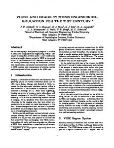
Fig. 11.1: A V-Model variant for CPPS Engineering.
Interchange Format (PMIF) for performance modeling and analysis (e.g., via queuing networks to calculate performance indices like resource utilisation) (Cortellessa et al., 2011), and (iv) model transformations as a strategic mechanism to integrate heterogeneous artifacts throughout the engineering of CPPS to deal with heterogeneities and to realize horizontal and vertical integration to ensure a holistic view on the resulting technical system and to assemble different views 1 (cf. Chapter 1, RQ C2). On top of these modeling and data exchange standards, model-based design and analysis methodologies can be devised in order to demonstrate the value of MDSE both in design and validation phases. For this purpose we use the V-Model2 , presented in Fig. 11.1 as methodological foundation in order to express our framework in a technology neutral way. Generally, the V-Model is a graphical representation of a system’s development life-cycle specifying the sequence of steps during a generic engineering process. These steps include system design, domain specific engineering, system integration, as well as the verification and validation of system properties (Verein Deutscher Ingenieure (VDI), 2004). The V-Model has proven as structural approach for the development of interdisciplinary technical systems like CPPS (cf. Chapter 2 for more details). In particular, we propose in this book chapter an example of a model-based Systems Engineering Technical Process. We relate the MDSE standards to the inner 1
Chapter 2 also discusses vertical and horizontal integration terms in the context of model-based engineering. 2 See Chapter 2 for an introduction and comparison among engineering process models.
11 MDSE: Principles and Application in the CPPS Domain
5
wings of the V-Model to cover that phases of the V-Model needed to realize and analyze the engineering of CPPS and to support cross-disciplinary modeling built on MDE techniques. We utilize the synergies between MDSE and the V-Model to guide stakeholders to select and combine appropriate standards, languages, profiles, and formats to build their own MDE methodology (e.g., performance analysis methodology) as needed for CPPS engineering on top of these standards (e.g., AML and PMIF). The intention of this chapter is to provide an overview on how different standards for MDSE may be combined on the macro-perspective to cover different engineering phases and not to provide a complete treatment of each engineering phase in detail. For the latter, we provide pointers to existing literature. The rest of this chapter is organized as follows. Section 11.2 provides a general introduction into model-driven engineering (MDE) and presents two major techniques of it: metamodeling and model transformations. Based on this foundation, we elaborate in Section 11.3 on a set of appropriate industry standards to apply MDSE techniques for CPPS engineering. In Section 11.4, we present examples based on a reference case study to show how the standards and techniques presented in the Section 11.3 are applied to realize CPPS and provide a critical discussion of the results. Finally, Section 11.5 concludes the chapter and outlines future challenges in MDSE.
11.2 Model-Driven Engineering in a Nutshell Before we discuss in more detail how MDSE can be actually realized in the CPPS domain, we provide a general introduction into model-driven engineering (MDE). MDSE may be seen as a special interpretation and application of the general paradigm of MDE within the systems engineering domain. In MDE, the abstraction power of models is applied to tackle the complexity of systems (Brambilla et al., 2012; Schmidt, 2006). MDE follows the principle “everything is a model” for driving the adoption and ensuring the coherence of modeldriven techniques, in the same way as the principle “everything is an object” was helpful in driving the object-oriented techniques in the direction of simplicity, generality, and integration (Bezivin, 2005). Historically, MDE has been mainly applied in software engineering (Brambilla et al., 2012; Bezivin, 2005; Schmidt, 2006), but in recent years, the application of MDE has been increasing in the CPPS domain as well (Vyatkin, 2013; Hegny et al., 2010; Sch¨utz et al., 2014). A key principle of MDE is to address engineering with formal models, i.e., machine-readable and processable representations. Based on this foundation, modeling provides a set of advantages for driving the engineering process. The application of model validation, testing, verification, simulation, transformation, and execution enables the automation of engineering process steps and support the traceability of engineering artifacts to improve quality management to mention just a few benefits (Brambilla et al., 2012).
6
Berardinelli et al.
Furthermore, in MDE, models are considered to be connected (i.e., model elements may be linked beyond the boundary of one model) and dynamic (i.e., models may be analyzed and executed in some form) (Brambilla et al., 2012; Bezivin, 2005). Models can be (i) compared to reason about differences between model versions, (ii) merged to unify different versions of a model, (iii) aligned to create a global and integrated representation of the system from different viewpoints to reason about consistency, (iv) optimized to improve their internal structure without changing their observable behavior, (v) refined to produce platform-specific models from platform-independent models, and (vi) translated to other formalisms for code generation, verification, and simulation. Dedicated tool support for these tasks is available out-of-the-box in modeling environments, which can be customized for the modeling languages in use. The two major MDE techniques are: (i) metamodeling for specifying modeling languages, i.e., the structure and content of valid models, and (ii) model transformations to systematically manipulate models. In the following, we discuss these two techniques to provide the basis for subsequently showing how these techniques are used in MDSE.
11.2.1 Metamodeling Metamodels play an important role in MDE (K¨uhne, 2006). They specify the abstract syntax of modeling languages (i.e., the language concepts and their relationships) that is the center of the modeling language definition and all other concerns such as concrete syntax (i.e., model notation) and semantics are defined based on these metamodels (Brambilla et al., 2012). MDE provides standardized metamodeling languages (also referred to as meta-metamodels) used for producing modeling environments such as the Meta Object Facility (MOF) (Object Management Group (OMG), 2003) for defining modeling languages that may be seen as pendant to Extended Backus-Naur Form (EBNF) (Wirth, 1977), which is the foundation for specifying textual languages. MOF is based on a core subset of UML class diagrams, i.e., classes, attributes, and references. A metamodel gives the intentional description of all possible models within a given language. Practically, metamodels are instantiated to produce models which are in essence object graphs, i.e., they consist of objects (instances of classes) representing the modeling elements, object slots for storing values (instances of attributes), and links between the objects (instances of references), which have to conform to the UML class diagram describing the metamodel. Therefore, models are often represented in terms of UML object diagrams if their concrete syntax is neglected. This is especially true when models are automatically processed by the computer. A model has to conform to its metamodel which is often indicated by the conformsTo relationship (cf. Fig. 11.2). In addition to the constraints defined by the metamodel, additional constraints may be defined based on the metamodel ele-
11 MDSE: Principles and Application in the CPPS Domain
7
«Meta-language»
Meta-Metamodel «conformsTo» «Language»
Metamodel «conformsTo» «Sentence»
Model «represents»
System
Fig. 11.2: Metamodeling pattern based on (K¨uhne, 2006).
ments using a constraint language. The Object Constraint Language (OCL) (Object Management Group (OMG), 2010) is a standardized and formal language to describe expressions, constraints, and queries on models. As such, OCL is the language of choice for defining constraints going beyond simple multiplicity and type constraints defined by UML class diagrams and metamodels. Based on this meta-layer architecture, metamodeling environments allow generating modeling environments and providing generic tool support, which can be employed for all the modeling languages defined within a metamodeling environment. Thus, metamodeling environments empower the knowledgeable tool users to become tool developers, e.g., modeling languages may be easily extended with new modeling concepts or completely new languages may be developed without programming efforts.
11.2.2 Model Transformations In a general sense, a model transformation is a program executed by a transformation engine which takes one or more models as input to produce one or more models as output as is illustrated by the model transformation pattern3 (Czarnecki and Helsen, 2006) in Fig. 11.3. In MDE, model transformations are used to solve different tasks (Czarnecki and Helsen, 2006; Mens and Gorp, 2006; L´ucio et al., 2016) such as code generation, model refactoring, reverse engineering to name just a few. One important aspect is that model transformations are developed on the metamodel level, and thus, are reusable for all valid model instances. In the MDE field, various model transformation kinds emerged in the last decade (Czarnecki and Helsen, 2006; Mens and Gorp, 2006; L´ucio et al., 2016) 3
Please note that the terms source/target models and input/output models are used synonymously.
8
Berardinelli et al. «metamodel»
Transformation Language «conformsTo» «metamodel»
«refersTo»
Source Language
Source Model
Transformation Specification «executes»
«conformsTo» «model»
«model»
«reads»
Transformation Engine «writes»
«refersTo»
«refersTo»
«metamodel»
Target Language «conformsTo» «writes»
«model»
Target Model «refersTo»
«model»
Trace Model
Fig. 11.3: Model transformation pattern based on (Czarnecki and Helsen, 2006).
whereas two important kinds are differentiated in the following. A model transformation can be categorized as out-place if it creates new models from scratch, e.g., producing an analysis model from a design model, or as in-place if it rewrites the input models until the output models are obtained, e.g., as it is the case in model execution or model optimization. Several transformation languages emerged in the last decade which provide dedicated support for defining model transformations (Czarnecki and Helsen, 2006; Mens and Gorp, 2006). In this book chapter we are focussing on out-place transformations as we are interested in automating the transition from the early design steps to early validation steps as well as to the subsequent discipline-specific engineering tasks. Thus, our goal is to apply out-place transformations to produce from a design model other representations which can be used in discipline-specific tools as well as analysis tools. For defining out-place transformations in this book chapter, we make use of the Query/View/Transformation (QVT) standard (Object Management Group (OMG), 2016a) which provides several languages to implement model transformations (Kurtev, 2007). For instance, by using the declarative QVT Relations language, transformation logic between two different metamodels is specified as a set of relations that must hold for the transformation to be considered successful. Relations contain a set of patterns used to match for existing source model elements in order to instantiate new target model elements or to modify existing ones. Since declarative approaches like QVT Relations allow for the specification of what has to be computed but not necessarily how, the transformations are defined in a very concise manner which allows to focus on the relations between different concepts instead of reasoning about how to encode them in imperative statements. Another benefit of using a declarative language such as QVT Relations is to allow for different application possibilities of the transformation specification. While the transformation can be executed in both directions, it is also possible to use the transformation to compare different models (if all relations are fulfilled by the source and target models) and in cases where
11 MDSE: Principles and Application in the CPPS Domain
9
differences exist, i.e., some relations are not completely fulfilled by the existing model elements, synchronization may be performed to restore the fulfillment of all specified relations. In this book chapter we focus on the classical forward transformation capabilities of QVT Relations and refer the interested reader for other execution capabilities to (Stevens, 2010). However, we also see the comparison and synchronization capabilities of QVT Relations as interesting ingredients to further automate the system engineering process, e.g., consider change propagation and reverse engineering activities to mention just a few practical engineering tasks. Finally, by instantiating the relations on the model level, a trace model is produced for indicating which source elements have been transformed to which target elements by which relation (cf. bottom of Fig. 11.3). After presenting the central techniques of MDE, we now proceed with their application in the domain of CPPS engineering. In particular, we elaborate on a selected set of standardized languages which are supported by metamodels in Section 11.3 and combine them in an automated engineering tool chain in Section 11.4 with the help of model transformations.
11.3 Selected MDSE Standards for CPPS Engineering In this section, we elaborate on a selected set of industry standards to introduce MDSE in the CPPS domain. This selection is far from being exhaustive, rather it aims at providing a coherent subset of modeling standards, proposed by the experience of the authors. These standards can be suitably integrated in model-driven methodologies for CPPS design activities as well as for the early verification and validation activities . In particular, we selected (i) SysML, a general purpose graphical modeling language explicitly devised for requirements specification and system design, (ii) AML for realizing data exchange among production system engineering tools, and (iii) PMIF for supporting performance modeling via the queuing network (QN) notation and as standardized data exchange format among QN solvers. By using these proposed standards, we can take full advantage of those MDE techniques presented in the previous section to automate a particular engineering tool chain framework which focusses on design, data exchange, and analysis. This framework is not limited to the presented set of standards as also other standards may be used within this framework. In the following, we describe each of the selected standards at a glance and give pointers to external resources for the interested reader.
10
Berardinelli et al.
11.3.1 Systems Modeling Language (SysML) SysML is a graphical modeling language standardized by the Object Management Group (OMG) for the development of large-scale, complex, and multi-disciplinary systems (Object Management Group (OMG), 2016b). SysML is derived and extended from the Unified Modeling Language (UML), a graphical, general-purpose software modeling language that is currently the most adopted one in model-based software engineering (Hutchinson et al., 2011). SysML reuses a subset of UML elements and introduces new elements, e.g., for requirements modeling. SysML is defined as a UML profile. In addition to SysML, several other UML profiles have been standardized by the OMG such as the MARTE profile (Object Management Group (OMG), 2016c) which we will discuss later. To better understand the relationship between UML and SysML, we will explain it in more detail. With UML profiles, UML provides a language-inherent extension mechanism for customizing UML concepts for particular domains and platforms. This mechanism allows engineers to extend UML to create new modeling concepts (derived from existing ones) comprising specific properties that are suitable for the domain of interest. A stereotype, denoted by the keyword , is one of three types of extensibility mechanisms, the other two are tagged values and constraints (Booch et al., 2005). By using stereotypes any UML metaclass can be extended with additional meta-attributes (i.e., tagged values) and additional modeling constraints. The profiling mechanism has been extensively adopted by the UML community to broaden the adaption of UML as design modeling notation in several domains. For more details, we refer the interested reader to (Booch et al., 2005; Seidl et al., 2012). SysML provides modeling concepts and diagrams for representing requirements, structure, behavior, and parametrics (i.e., mathematical constraints) of a system which are linkable to trace requirements and to connect structure with behaviour (cf. Fig. 11.4). We now present only a small subset of SysML which we use later on in Section 11.4.2.1. To represent the structure of systems, the UML class diagram and composite structure diagram are adapted and renamed into block definition diagram (BDD) and internal block diagram (IBD) by SysML. By using BDD, the structural decomposition of a system into so-called blocks can be defined. A block represents a modular component of a system. Its definition comprises the component’s properties and relationships to other components. Important relationships between blocks include: • Composition relationships representing the decomposition of a block into subblocks (called parts); • Reference associations representing logical references between blocks which are parts of different composite blocks; • Dependency relationships denoting that a change on one block may cause a change on other blocks; • Generalization relationships representing classifications of blocks.
11 MDSE: Principles and Application in the CPPS Domain
11
pkg SysML Model Organization System Model
Behavior
Requirements
Structure
act [Activity] Behavior::A0
req [Package] Requirements
:System
bdd [Package] Structure
Parametrics
par [Block] Parametrics
:Actor
property 1
System values
R1
property 1
R1.1
R1.2
:C1
:A1 :A2
Comp 1
Comp 2
values
values
property 1.1
property 2.1
property 1.1
property 2.1
ibd [Block] System :Comp 1
:Comp 2
Fig. 11.4: Overview on SysML diagram types and their connections (Friedenthal et al., 2014).
By using IBD, the connections between parts of a compound block can be defined. In particular, they include: • Ports to define connection points between blocks; • Connectors to connect blocks via ports and enable interaction. SysML provides an integration framework for discipline-specific design models, e.g., mechanical, electrical, and software models. The system model captures the overall design of a system on a high-level of abstraction and traces this design to discipline-specific models. For this reason it fits to the multi-disciplinary engineering process required for realizing CPPS (cf. Fig. 11.1). SysML has been already adopted in several domains4 for developing complex and multi-disciplinary systems, e.g., in the aerospace and defense industry. SysML is now also emerging in the automation domain (Feldmann et al., 2014). As SysML is a profile extension of UML, model-driven techniques and tools are directly applicable to this standard. For more information on SysML, we kindly refer the interested reader to (Alt, 2012).
11.3.2 Modeling and Analysis of Real-Time Embedded System Profile (MARTE) MARTE (Object Management Group (OMG), 2016c) is another standard introduced by the OMG. MARTE’s target modeling domain includes reactive systems interacting with the external environment through sensors and actuators, e.g., consider transportation, factory automation, hardware/software controllers, and various embedded electronic appliances also including mobile communications. As MARTE 4
See http://www.omgsysml.org for an overview.
12
Berardinelli et al. Class diagram System Design
in
Production System
Machine A {resMult = 1, schedPolicy = FIFO}
- processItem(i:Item)
items * c
a in
out
out in
activity processItem
b
Machine B {resMult = 1, schedPolicy = FIFO}
Machine C in {{resMult = 1, schedPolicy = FIFO} - processResource
out
out
- processResource(i:Item)
Composite Structure Production System
i:Item «GaStep» {hostDemand = (10, sec), prob=1} process
Item
:Item
:Item
:Machine B
Machine A
:Item
:Item
:Item
:Machine C :Machine B
:Item
Fig. 11.5: A production system modeled in UML with MARTE annotations.
is designed as a UML profile, it is applicable to UML, and by this, also to all other UML profiles such as SysML. MARTE includes many sub-profiles structured around two main concerns (i) modeling software and hardware structures, e.g., by the software resource model profile and hardware resource model profile, and (ii) enriching design models to obtain analysis models with additional parameters required by model-based methodologies for performance and schedulability analysis (e.g., response time of software/hardware execution hosts or scheduling policies of tasks). Fig. 11.5 shows a simple example of a production system modeled in terms of a UML class diagram with annotations from a subset of the MARTE profile. By using MARTE, the role of different classes can be identified. A production system can be considered as a collection of active resources, e.g., machines. As shown in Fig. 11.5, the production system is composed by three different kinds of machines, Machine A, Machine B, and Machine C. The production system’s layout is presented by a composite structure diagram (cf. Fig. 11.5, on the bottom right). It includes 4 machines in total (one of type A and one of type C, both, connected by two machines of type B). In our example, these machines provide processing services for items entering the system to be processed by Machine A, flowing through Machine B, and then leaving the system after the last processing step carried out on Machine C. This flow is indicated by the black triangles showed in the composite structure diagram of the production system. Thereby, each item is processed following a firstin-first-out (FIFO) scheduling policy. Additionally, quantitative information can be annotated on structural (e.g., the resources’ multiplicities) as well as on behavioral specifications. For example, timed properties can be assigned to actions as shown in the processItem activity diagram. In this diagram the modeling behavior of processItem() operation of Machine A is described. Each execution of the
11 MDSE: Principles and Application in the CPPS Domain
13
processItem() operation lasts (exactly) ten seconds, seizing its execution host, the Machine A instance shown on the composite structure diagram. MARTE provides concepts required for model-driven design and analysis of systems, but it is independent of any design and analysis methodology. Moreover, the general framework for quantitative analysis provided by MARTE is intended to be refined/specialized for the specific methodology of choice (e.g., dependability analysis (Bernardi et al., 2011)). As for SysML, MARTE is a profile extension of UML, thus model-driven techniques and tools are directly applicable to this standard. For more information on MARTE, we kindly refer the interested reader to (Object Management Group (OMG), 2016c; Selic and G´erard, 2013).
11.3.3 Performance Modeling Interchange Format (PMIF) PMIF is conceived as a common representation for system performance model data that could be used to move queuing network models between analysis and simulation tools (Smith and Williams, 1999). Its creators were interested in tool interoperability for performance engineering (Smith, 1990). The first version of PMIF (Smith and Williams, 1999) addresses a specific type of performance model, i.e., queuing network models that may be solved using analytical solution algorithms. Providing enhanced support for extra-functional modeling and analyses of CPPS is in particular of high importance in the early design and validation steps (Malavolta et al., 2013). In this regard, queuing network (QN) models provide a powerful notation widely used to represent and analyze resource sharing systems like CPPS (Schleipen and Drath, 2009). As summarized in (Cortellessa et al., 2011): Informally, a QN is a collection of interacting service centers representing system resources and a set of customers representing the users that share the resources. It can be represented as a direct graph whose nodes are service centers and edges represent the potential paths of customers service requests. Several different classes of customers can circulate over the network at the same time, each class representing a set of customers with homogeneous behavior (i.e., paths and amounts of service requests).
The construction of a QN can be split in two main steps, (i) definition of service centers, their number, and the interconnections, and (ii) parameterization of the arrival processes, i.e., the definition of job classes, the service rates, scheduling policies and the routing probability among servers. Fig. 11.6 gives a graphical overview of a generic QN model, its typical modeling elements, and their relationships as already defined for the production system modeled with UML/MARTE in Subsection 11.3.2. Each machine instance is represented as a server. The produced items are instances of the same job class. Jobs enter the system at a certain arrival rate and flow to servers, waiting for being served, seizing the server for a certain amount of time (a.k.a., service time) then proceed to the next server connected with arcs until they leave the system through sink nodes. PMIF provides a common serialization format for this kind of models. In this paper, we adopt a variant of the PMIF metamodel presented in (Troya and Val-
14
Berardinelli et al.
job class
item
workload generator source
server
Machine B1 sink
arc
Item generator
queue
Machine A
Machine B2
Machine C
Fig. 11.6: A production system modeled as an open queuing network.
lecillo, 2014), suitably updated for being easily integrated in model-driven performance analysis methodologies. Following this variant, a QN model is a graph with Nodes connected by Arcs. There are two types of nodes, Servers and NonServers. The former provide a processing service while the latter represent origin (SourceNode) and exit (SinkNode) for entities flowing through the QN. These entities are referred as customers or jobs. Different job classes are defined through workloads (Workload). A Workload can be open or closed depending on the capability of jobs to enter/leave the QNM (i.e., open) or not (i.e., closed with a fixed job number). Any Workload specification includes the sequence of transits to different Server where jobs can ask for one or more service requests (ServiceReq). At each Server, the next job to be processed is decided by a scheduling policy (e.g., first-come-first-served). Finally, timed properties like job inter-arrival time (for open workload), and service times (for servers) are usually given as part of a performance analysis scenario (e.g., arrival probability distribution). Other timed properties (e.g., the waiting and completion time for single jobs or for the whole workload) are obtained as part of analysis results and used by tools to compute performance indices. There are currently several tools for solving QN models providing their own model representations. In (Troya and Vallecillo, 2014), the reader can find a recent list of QN solvers together with their evaluation techniques (e.g., analysis or discrete event simulation), model format, allowed probability distributions (e.g., for generating inter-arrival times and service times) and supported QN types (e.g., open/closed). As we build on the existing metamodel for PMIF (Troya and Vallecillo, 2014), model-driven techniques and tools are directly applicable to this standard as well. For more information on QNs and PMIF, we kindly refer the interested reader to (Smith and Williams, 1999; Smith et al., 2010; Troya and Vallecillo, 2014).
11.3.4 AutomationML AML is a neutral, free, open, XML-based, and standardized data exchange format, which aims for data exchange within the engineering process of production systems (IEC, 2014). We present an overview on AML in Fig. 11.7. In particular, typical elements in an AML production system model comprise: (i) the plant struc-
11 MDSE: Principles and Application in the CPPS Domain
15
Fig. 11.7: AML overview taken from (IEC, 2014).
ture including devices and communication structures, expressed as a hierarchy of AML objects and described by means of CAEX which follows the standard IEC 62424 (Schleipen et al., 2008), (ii) geometry and kinematics represented by COLLADA 1.4.1 and 1.5.0 (ISO/PAS 17506:2012) (ISO/PAS, 2012), and (iii) control related logic data (i.e., PLCopen XML 2.0 and 2.0.1 (PLCopen, 2011)). Since the foundation of AML is the application of CAEX as top level format, we focus on this part of AML in this section and the following one. CAEX stores engineering information following a prototype-oriented paradigm. It allows the modeling of physical and logical system components as data objects encapsulating different aspects. CAEX objects (namely, internal elements IE) and their interfaces (namely, external interfaces ExtI) can be specified from scratch or suitably instantiated (that means cloned) from existing prototypical classes (namely, SUC), defined and collected in system unit class libraries (SUClib). Both CAEX objects and classes may consist of other sub-elements, and may themselves be part of a larger composition or aggregation. Both classes, objects, and their interfaces are semantics agnostic. CAEX provides role classes (RC) and interface classes (IC) to assign semantics to IEs and ExtI, respectively. Both RC and IC are defined and collected in libraries (RClib for RC and IClib for IC). AML objects and classes can then support and/or require such roles. Finally, individual objects are modeled in an instance hierarchy (IH) which, in turn, may contain internal elements (IE). IEs can be instantiated from SUCs and arranged in accordance with the supported and required roles. External interfaces (ExtI), instantiated from ICs, are used to interlink objects (IL) among each other or with externally stored information (e.g., COLLADA or PLCopen XML files). In previous work (Biffl et al., 2015), we have defined a metamodel for AML considering the CAEX part. Using this metamodel, we can represent AML data as models and apply model-driven techniques and tools for AML as well. This allows, e.g., to transform system models defined in SysML to AML and vice versa.
16
Berardinelli et al.
For more details about AML, we kindly refer the interested reader to the different AML whitepapers available at (IEC, 2014). In addition, Chapter 9 of this book focuses on the role of AML as a potential standardized data format and it is exemplarily presented for the case of virtual commissioning of a production system.
11.3.5 Synopsis To sum up this section, we presented four different modeling languages which are all based on metamodels which are directly defined by standardization bodies or by the scientific community. This is an important requirement as this already resolves the potential data model heterogeneities and allows to represent the models in the same format as well as to manipulate them with the same tools and techniques. We exploit this feature in the following section to combine the presented languages in an automated engineering tool chain framework.
11.4 MDSE of CPPS in Action In this section, we show how the presented languages of Section 11.3 can be combined to support the envisioned CPPS engineering process. Fig. 11.8 depicts how these languages are aligned with the engineering activities of the V-Model: • Requirements and design language: We use SysML as a front-end requirements and design notation. In particular, we model the requirements of the system as well as its design covering its structure and behavior. Furthermore, we show how MARTE stereotypes can be used to provide the necessary information to perform early performance analysis. • Data exchange language: AML is primarily devised as a data exchange among automation tools in our engineering tool chain. It eases vertical integration with other domain-specific activities (e.g., virtual commissioning with COLLADAbased tools and PLC programming (L¨uder et al., 2015)). In particular, we show how the information defined in the SysML model can be exchanged on the basis of CAEX. • Analysis language: PMIF is employed to share models with QN solvers to compute properties of interest for early design validation. In order to analyse the performance of a design given in SysML and MARTE, we compute the necessary properties to validate if the stated requirements are fulfilled or not with the help of an existing QN solver. As we will see later, the transitions between the different engineering activities are automated by model transformations. This allows to exchange the design models between engineering tools used in the discipline-specific engineering activities, as well as to perform early validation and verification of the design models before
11 MDSE: Principles and Application in the CPPS Domain
17
Fig. 11.8: Populating the V-Model with concrete languages for requirements & design, data exchange, and analysis.
the discipline-specific engineering activities start. Furthermore, we would like to highlight that based on the trace model generation by model transformation engines, traceability between the design models, data exchange models, as well as analysis models is provided automatically. The rest of this section is organized as follows. We first provide the description of a reference case study, a lab-sized production system hosted at IAF of the Otto-v.Guericke University Magdeburg (Equipment Center for Distributed Systems, 2016) which is subsequently used as a running example to exemplify the integration of SysML, PMIF, and AML as well as to discuss its benefits and challenges. First, we provide three different models of this given production system using SysML, AML, and PMIF as modeling languages for the sake of CPPS design (via SysML), data exchange, (via AML) and early model-based validation activities (e.g., performance analysis through queuing network represented by PMIF). Second, we describe how the integration between (i) SysML and AML and (ii) AML and PMIF has been realized to automate the validation of requirements on SysML design models.
11.4.1 Case Study The IAF production system (cf. Fig. 11.9) consists of a transportation line made of sets of turntables, conveyors, and multi-purpose machines. Each turntable is equipped with an inductive proximity sensor for material detection and a motor for table rotation. The transportation line is wired to a modular fieldbus I/O system, which, in turn, communicates with Raspberry Pi based controllers by Ethernet. The Raspberry Pi based controller is running a Programmable Logic Controller
18
Berardinelli et al. PI CONTROLLERS FIELD BUS CONTROL CABINET MULTI-PURPOSE MACHINE
TURNTABLE
ITEM
CONVEYOR
AREA 1 AREA 2
AREA 3
Fig. 11.9: The lab-sized production system hosted at IAF of the Otto-v.-Guericke University Magdeburg (Equipment Center for Distributed Systems, 2016).
(PLC) program (PLCopen, 2011) governing the transportation line. Such programs logically divide the transportation line in three areas as depicted in Fig. 11.9. The production plant is supposed to continuously processes items via its multi-purpose machines located in different areas. Turntables and conveyors are in charge of moving such items to these machines following a predefined process5 .
11.4.2 CPPS Modeling Systems design is the process of defining (i) the architecture, in terms of components, modules, interfaces, and (ii) the functionalities that such a system should provide in order to satisfy the specified requirements. In the following, we design a CPPS virtual prototype of the reference case study using SysML and AML. Then we build a QN performance model based on PMIF to validate the virtual prototype. We represent the overall structure and behavior of the transportation line that is further decomposed in three groups of resources, called areas. We then provide a detailed design of Area1, the leftmost logical area in Fig. 11.9, together with its internal resources (i.e., four turntables, four conveyors, and one multipurpose machine) as well as resource-specific behaviors. Of course, the proposed models can be built from scratch in the different stages of the engineering process and they can be used isolated for documentation purposes 5
Models realized for this case study can be downloaded from our companion web site at the following address http://www.sysml4industry.org/wp-content/uploads/2016/08/ models-1.zip
11 MDSE: Principles and Application in the CPPS Domain
19
req IAF Plant Requirements
Logical Areas
Item Production
id#: FR 1 txt: The IAF plant system is composed by processing stations without buffering capacity. At any time, during the production process, no raw products can be buffered for delayed processing. «satisfy»
«satisfy»
Area
id#: NFR 1 txt: The IAF plant produces items. The production process of a single item should last less than a minute.
«satisfy» IAF Plant
«derivedFrom»
«verify» IAF Plant
Fig. 11.10: Excerpt of the SysML requirement model of the IAF Plant.
(e.g., by SysML diagrams) or for analysis purposes (e.g., calculating the minimum, maximum or average processing time for items). However, in order to realize an efficient engineering process realizing the potential benefits of formal models, repetitive manual tasks should be eliminated as much as possible. Instead model transformations should be employed for automating these tasks as much as possible.
11.4.2.1 Modeling in SysML We employ SysML (Object Management Group (OMG), 2016b) to support requirements specification and system design of the CPPS engineering process as sketched in Fig. 11.8. Figs. 11.10 and 11.11 show parts of the IAF plant SysML model which we discuss in the following. SysML provides modeling concepts and a diagram type to represent text-based requirements and their relationships to other SysML modeling elements, as discussed in Section 11.3. The requirements diagram in Fig. 11.10 depicts functional (FR) and non-functional (NFR) requirements for the IAF Plant. The FR prescribes a constraint on the logical architecture of the transportation line, which has to be divided in three distinct areas of turntables, conveyors, and machines. This requirement will probably affect the logical representation of the transportation line as programmed in the PLC code deployed on Raspberry PI controllers (cf. Fig. 11.9). The NFR states a production constraint setting a minimum production threshold. This is a typical performance requirement that can be validated through analysis of a queuing network representation of the IAF Plant. For this reason, we extend the SysML design of the IAF Plant with MARTE annotations and derive a PMIFbased queuing network for the sake of requirements validation. Both requirements describe system-level properties, which have to be satisfied by the whole IAF plant. For this reason, a satisfy relationship is depicted from
20
Berardinelli et al.
the top-level structural SysML block representing the whole IAF plant to these requirements. Concerning the design of the IAF Plant, the structural elements and their relationships are defined via blocks and containment relationships in the BDD in Fig. 11.11a. A top level IAF Plant block includes an Area block, which in turn has Turntable, Conveyor, and Machine blocks. The ports depicted on the blocks’ borders represent the potential input (e.g., inA, for receiving Areas), output (e.g., outT from Conveyors to Turntables), and bidirectional (e.g., in outC, for Machines interacting with Conveyors) interaction points among these structural elements. Finally, blocks can be used to define the product types, e.g., the generic item shown as wooden piece in Fig. 11.9. The IBD depicted in Fig. 11.11c defines the structure of the transportation line with three connected areas. We then detail the internal structure of the Area 1 as a graph of parts, ports, and connectors. Parts represent tX and cX properties in the BDD with the following naming convention: ’part name’: ’type name’, where ’type name’ refers to the corresponding block defined in the IAF Plant Design BDD (e.g., t1:Turntable). Connectors have both structural and behavioral functions, specifying both (i) links between parts via ports, and (ii) item flows between parts depicted with black directed arrows. Once the system architecture has been defined, we proceed with the behavioral specification6 of processing resources, i.e., Turntable, Conveyor, and Machine blocks by defining the resource-specific operations turn(), transfer(), and process(), respectively, applied on items. The detailed behaviors are modeled through Activity Diagrams in Fig. 11.11b. Each activity is realized with a single action receiving the parameter Item i (i.e., the box at the border of the activity diagram). In Fig. 11.11d such operation-specific activities are combined in a systemlevel activity where a workflow of call operation actions correspond to the processing steps applied on items flowing through Turntables, Conveyors, and Machines placed in the Area1 of the IAF Plant. We assume that the processing starts at turntable T0 and proceed up to turntable T2. Here the item can leave Area1 to be processed by resources placed in Area2, or continue to conveyor C2. A similar alternative choice happens in turntable T3, where the item can be moved to Area2 or to conveyor C3 where the whole is supposed to restart from the beginning at turntable T0. This processing scenario is realized on top of the IAF Plant layout shown in the IBD in Fig. 11.11c. We now proceed with the description of how MARTE is used to analyze the given design model with respect to the requirements model.
6
It is worth noting that SysML provides different behavioral notations and diagrams such as State Machines and Interactions (a.k.a., Sequence Diagrams). It is up to the modeler to choose the notation that better fits with her needs.
11 MDSE: Principles and Application in the CPPS Domain
a)
area1
Block Definition Diagram BDD
IAF Plant Design
area2 area3
«Block», «GaResoucePlatform»
Area
{resMult = 3, throughput = $th, respT = $rt, utilization= $u}
IAF Plant
Item
Turntable t2 {resMult = 4, schedPolicy = FIFO, throughput = $th, respT = $rt, utilization= $u} t1 t0 - turn (i:Item) inC
outA m1
c3 t3
«Block», «GaExecHost»
{resMult = $num_job}
inA
{resMult = 1, schedPolicy = FIFO, throughput = $th, respT = $rt, utilization= $u}
«Block», «GaExecHost»
i:Item
T Process Operation
«Block», «GaExecHost»
Conveyor
c2
Machine
{resMult = 4, schedPolicy = FIFO, c1 throughput = $th, respT = $rt, utilization= $u} c0 - transfer (i:Item)
inT
in_outM
outC
Activity Diagram
«Block», «Resource»
generate(): Item «GaWorkloadEvent» {pattern=open(arrivalRate=(exp,0.01,sec)), generator=Item_Processing}
«Block», «GaResourcePlatform»
b)
21
c)
{resMult = 1, schedPolicy = FIFO, throughput = $th, respT = $rt, utilization= $u} - process (i:Item)
outT
in_outC
Internal Block Diagram IBD
area1
«GaStep» {hostDemand = (exp, 0.1, sec)}
m1: Machine :Item
:Item
turning
Activity Diagram
:Item
c2: Conveyor
c0: Conveyor
«GaStep» {hostDemand = (const, 2, sec)}
transfering
:Item
:Item
:Item
:Item
t0: Turntable
i:Item
Activity Diagram
:Item
:Item
:Item
C Process Operation
t2: Turntable
c1: Conveyor
t1: Turntable i:Item
t3: Turntable
c3: Conveyor
M Process Operation «GaStep» {hostDemand = (const, 2, sec)}
Area 3
processing
d)
Activity Diagram
outA inA
Internal Block Diagram IBD Internal Block Diagram IBD
Area 2
«GaScenario» {throughput = $th, respT = $rt, utilization= $u}
Item Processing
«CallAction»
«CallAction»
T0: turn
i:Item
C0: transfer
i:Item
…
«CallAction»
M1: process
i:Item i:Item
«CallAction»
T2: turn
i:Item
…
«CallAction»
T3: transfer
i:Item
«CallAction»
C3: transfer i:Item
Fig. 11.11: Excerpt of the SysML design model of the IAF Plant.
NO AML ANNOTATIONS
11.4.2.2 Profiling SysML models with MARTE In MARTE, a system is a platform where resources provide services that can be acquired and released. In this respect, both, the whole IAF plant and its areas are identified as platforms (GaResourcePlatform). The structural constraint im-
22
Berardinelli et al.
posed by the FR requirement in Fig. 11.10 suggests to consider also the Area block as a logical sub-collection of resources as depicted in Fig. 11.9. MARTE allows the distinction of different kinds of resources depending on specific purposes, i.e., processing, storage, and communication. In particular, in performance modeling a GaExecHost can be any resource that executes behavior. Therefore we applied this stereotype to SysML blocks modeling the resources of the IAF transportation line, i.e., Turntable, Conveyor, and Machine, which host and provide turn(), tranfer(), and process() operations as services to accomplish the production of items depicted in Fig. 11.11d. The aforementioned stereotypes come with predefined properties which act as placeholders (i) to store input parameters required to generate analysis models from SysML ones and (ii) to store output results generated by the chosen analysis tools. In order to enable the validation of the NFR requirement imposing a timing constraint on the item production process, we require the model-driven generation of a queuing network model representing the Area 1 of the IAF transportation line. MARTE explicitly supports performance analysis with its Generic Quantitative Analysis Model (GQAM) and Performance Analysis Model (PAM) subprofiles (Object Management Group (OMG), 2016c). The performance model parameters can be partitioned in the following main categories: (i) the operational profile, (ii) the workload, (iii) the resource demands. The operational profile is a collection of data that stochastically represent the usage that agents make of a system in a certain environment. A typical parameter is the probability to invoke a certain service. In this example, we consider a unique system-level service (i.e., item processing) then we omit this parameter (i.e., probability equal to one). The workload represents the intensity of system services requests from agents. It is annotated by the GaWorkloadEvent applied on the generate() operation on the Area block that collect all the resources involved in the production process. Items enter Area1 from turntable T0 and leave it from turntables T2 and T3, therefore we considered an open workload of items with a mean inter-arrival time of ten seconds (expressed as a Poisson distribution random variable)7 . Finally, resource multiplicities (resMult) and demands are annotated on GaExecHosts block and operations’ Actions in terms of execution times obtained, as for arrival pattern specification, random variables obtained from exponential (exp) and constant (const) probability distributions. The output of the analysis may also be stored in properties of MARTE. Common performance indices are throughput, response time, utilization but the possible performance indices and the granularity of the results depend on the capability of the chosen analysis tool8 . Indices can be calculated both at system-level or for single resources. We refer the reader to Section 11.4.2.3 for their description in context of the given case study. In Fig. 11.11 we store the output results that refer to a particu7
A closed pattern would be considered in a system-level production process involving all the resources of three areas. In that case a similar annotation would be applied on the IAF Plant block. 8 For an example, the reader can consolidate the manual of the JMT queuing network solver (Casale and Serazzi, 2011)
11 MDSE: Principles and Application in the CPPS Domain
23
lar behavioral modeling element, e.g., the Item Processing activity (GaScenario, throughput, respT, utilization properties), or to a particular structural one (GaResourcePlatform, throughput, respT, utilization properties). In MARTE, variables, shown as $-prefixed Strings in Fig. 11.11, can be used as placeholder to be replaced with actual results. It is worth noting that the annotation of SysML models should be considered as an integral part of model-driven methodology for early validation of systems adopting SysML as the main modeling notation. In this respect, MARTE does not prescribe the adoption of any annotation strategy or model-driven methodology. The interested reader is kindly referred to (Cortellessa et al., 2011) for a general overview on model-driven performance engineering and analysis methodologies.
11.4.2.3 Modeling in PMIF An excerpt of the IAF Plant modeled in PMIF is illustrated in Fig. 11.12. Such as AML, PMIF is primarily devised as an exchange standard for interoperability among queuing network (QN) solvers. Moreover, as discussed for AML, PMIF does not provide a standard concrete notation. Therefore we provide here an ad-hoc notation for the sake of explanation aided by a graph-oriented diagram. The legend on the right side of the diagrammatic representation relates this notation with PMIF concepts. The so-called queuing network topology (i.e., the graph of servers and arcs) of the IAF Plant QN model includes a distinct server for each turntable (Tx), conveyor (Cx), and machine (Mx), connected through arcs. A source node is connected to the turntable T0 and two sink nodes can be reached from turntable T2 and T3, where the item processed by the plant can leave the QN, i.e., the Area1 of the IAF Plant to enter Area2. The produced items that circulate among servers are referred as customer or job in the QN jargon. Jobs are generated and injected in the QN via T1 by a workload generator. The arrival process of item jobs is determined by a probability distribution that generate the inter-arrival times between consecutive arrivals. In this example, we considered a Poisson arrival process of items always (then probability set to 1) to T0. We then assume mutually independent arrivals of items every 100 seconds, on average (obtained from the reciprocal of arrival parameter 0.01, a.k.a. lambda parameter). The generated item jobs can potentially visit all the servers reachable by the QN topology. However, the possible paths of such jobs are determined by a collection of service requests (SR) that Item jobs require to the visited server. A subset of these SRs required by Items to T2, C2, and T3 servers (srv) are shown at the bottom of Fig. 11.12. They are expressed in term of service time (Time SR) during which the server is seized to process the current job before releasing to the next. Again, the service time is modeled as a stochastic variable governed by an exponential probability distribution whose average value is obtained as a reciprocal of the lambda parameter (e.g., 10 seconds for T3). It is worth noting how the transitTo and
24
Berardinelli et al.
item arrivalDistr: exp arrival Params: 0.01 time Units: sec Transit To: Source Item Transit Probs: 1
schedPolicy= FIFO Legend
Source_Item
= single queued server
M1
Sink_Area2
= source = sink
T1
C1
T2
= open workload = arc
C0 T0
C2
C3
Time SR
srv: T2 serviceDistr: exp service Params: 0.1 Time Units: sec Transit To: C2, Sink_Area2 Transit Probs: 0.5, 0.5
= job
Sink_Area2
= Time service request
T3 Time SR
srv: C2 serviceDistr: const service Params: 2 Time Units: sec Transit To: T3 Transit Probs: 1
Time SR
srv: T3 serviceDistr: exp service Params: 0.1 Time Units: sec Transit To: C3, Sink_Area2 Transit Probs: 0.5, 0.5
Fig. 11.12: Excerpt of IAF Plant modeled in PMIF.
transitProb attributes of T2 and T3 SRs contains two ordered values, one for each arc outgoing the server. The next server is then determined by pairing the value of these attributes. The resulting QN model can be directly modeled in PMIF using the xQNM tool presented in (Troya and Vallecillo, 2014) or in JMT (Casale and Serazzi, 2011). Fig. 11.13 shows some simulation results generated by JMT and annotated back on the IAF Plant SysML model by replacing the MARTE variables previously assigned to properties of MARTE stereotypes (cf. the $-prefixed terms in Fig. 11.11). We calculated the system response time and system throughput9 for the item processing scenario depicted in the activity of Fig. 11.11d. We conducted an early what-if analysis by increasing the arrival rate on items from 1 item per minute up to 1 item per second to test production capacity of that area. Area1 can manage up to 40 item arrivals per minute (0.674 item/sec) with an average response time (i.e., the time required to execute the activity Item Processing) of 56 seconds per item. This processing time for items does not violate the maximum processing time of 60 seconds allowed for the item production process (cf. the NFR in Fig. 11.10). 9
The QN model represents only Area1’s process and resources, therefore it corresponds to the system under analysis.
11 MDSE: Principles and Application in the CPPS Domain
25
However, the given response time is an average response time and the utilization of Area1’s resources rapidly grows to the critical 0.9 threshold (i.e., the resource is busy for the 90% of its time) as shown for machine M1. Therefore the production capacity of Area1 is currently limited to 40 items per minute and any increment in the production rate (e.g., to 45 item per minute, 0.750 item/sec) would cause the violation of the given requirement due to the increasing queue of items waiting for M1 processing. Thanks to these early analysis results, the modeler/analyst can then decide (i) to keep or reduce the current production rate of Area1, (ii) to increase the processing power of the multi-purpose machine M1, or (iii) to decrease the arrival rate of items, and then the production rate of Area1.
11.4.2.4 Modeling in AML An excerpt of the IAF Plant modeled in AML is shown in Fig. 11.14. It is worth noting that AML does not provide a standard concrete notation (such as SysML does). Therefore we provide here an ad-hoc notation for the sake of explanation in terms of a graph-oriented diagram. The legend below the diagrammatic representation of IAF Plant explains this notation with AML concepts. Following the requirements in Fig. 11.10, also the AML representation of the IAF Plant’s transportation line is divided in three areas (Area1, Area2, and Area3), each composed of turntables, conveyors, and machines. The root node is the IAF Plant instance hierarchy (IH). Its nested structure includes three internal elements (IE), one for each area that logically divide the transportation line. Then, the detailed architecture of Area1 is shown as a graph of IEs (L¨uder et al., 2013). Turntables (Tx IEs) and conveyors (Cx IEs) are nodes alternating each other in closed paths. An additional node for a machine M1 is linked to the C1 IE. Each IE has a predefined set of interaction points modeled as external interfaces (ExtI) connected via internal links (IL). According to (Schleipen and Drath, 2009), such IEs can be classified in (i) products, (ii) processes, and (iii) resources (PPR) (Schleipen and Drath, 2009). Resources are entities involved in the production that process and handle products. Depending on the reference engineering discipline, software, mechanical, and electronic elements can all be referred as resources collaborating to product handling. Products are the produced goods processed by the IAF plant through its resources. The IAF plant is supposed to produce a generic item that is moved by turntables and conveyors towards multi-purpose machines. Processes consist of processing steps realized by the IAF plant resources. The IAF plant provides a production process for items determining their movements among resources. Products, processes, and resources are all modeled as IEs as done for turntable T3, the processing step Turn realized by T3, and the product Item.
26
Berardinelli et al.
Activity Diagram
Item Processing
«GaScenario»
throughput = ( (0.017, 0.126, 0.235, 0.345, 0.455, 0.562, 0.674, 0.750) , job/sec, mean) respT = ( (10.110, 13.442, 16.937, 20.909, 25.779, 33.183, 56.251, 1.024E4) , sec, mean)
Activity Diagram
i:Item
M Process Operation «GaStep» {hostDemand = (exp, 0.017, sec) utilization = ((0.022, 0.169, 0.310, 0.462,0.610,0.745,0.902,0.966), real)}
processing
Fig. 11.13: Analysis results and their annotation on IAF Plant SysML model with stereotypes and properties of the MARTE profile.
The instance hierarchy with its internal elements, external interfaces, and internal links is semantic-agnostic, i.e., there is no distinction between nodes and arcs building such a graph-like structure. For this purpose, AML provides the role class libraries (RClib) and role classes (RC) concepts for nodes and interface class library and interface classes for external interfaces. In particular, AML provides several standard role class library (RClib) and interface class library libraries (IClib). The AML RClib defines Product, Process and Resource RC. We then build a PPR semantics layer in the IAF Plant IH structure by assigning Product, Process, and Resource role classes to the corresponding IEs of the IAF Plant instance hierarchy via role requirement relationships (RR) as shown in Fig. 11.14 for Item, Item Processing, and C0, respectively.
11 MDSE: Principles and Application in the CPPS Domain
27
IAF Plant
IH
Area2
Area1
IE
IE M1
IC
PPR Connector
(from AML library)
RC
IE C1
IE C0
RC
IE
IE C2 IE
RC
IE T0
IE
RC
IE
(from AML library)
GaScenario
RC
Process
(from PMIF library)
Turn
Transfer
C3
(from MARTE library)
GaExecHost
Item Processing
T2
T1 IE
(from PMIF library)
Server
IE (from MARTE library)
(from AML library)
Resource
Area3
IE
Turn
IE
RC
Service Request
(from MARTE library)
RC IE
GaStep (from AML library)
RC IE
T3
IE Item
Product
(from PMIF library)
RC
IH
= instance hierarchy (IH)
= external interface (ExtInt)
IE
= internal element (IE)
= internal link (IL)
= base class
IC
= interface class (IC)
= role requirement (RR)
= nesting
Open Workload
= supported role (SRC)
Legend
= PPR, MARTE, and PMIF semantics layers
Fig. 11.14: Excerpt of IAF Plant modeled in AML.
For the sake of the envisioned integration with SysML/MARTE and PMIF, we further enrich the AML model with two additional semantics layers. We created two new role class libraries, PMIF RClib and SysML/MARTE RClib that define the corresponding language-specific concepts by role classes of the same name. The PMIF RClib introduces in AML role classes like Server, Service Request, and Open Workload role classes. A PMIF semantics layer is then realized on top of the same IAF Plant IH by assigning these role classes to resources (e.g., C0), processing steps (e.g., Turn), and products (e.g., Open Worload) to facilitate the integration with PMIF as further discussed in Section 11.4.3.2. The SysML/MARTE RClibsupports the modeling of a AML semantics layer for these two OMG standards. We assigned the AML RC counterparts of MARTE stereotypes (GaExecHost, GaScenario, and GaScenario) to plant resources and processes to facilitate the integration of AML with SysML models annotated with MARTE, as discussed in Section 11.4.3.2.
28
Berardinelli et al.
11.4.3 CPPS Engineering Chain Automation The proposed engineering chain automation approach aims at bridging system design with early validation of system performance. As we discussed for the used modeling languages in the engineering chain, all of them are supported by metamodels which define the languages explicitly and also define the possible structures and content of the models. This allows model transformations to be formulated on the metamodel level which ensures their executability for any valid instance. However, to realize a valid transformation with a specific purpose, also the models have to be rich enough and systematically built by following modeling rules to be transformed to the target language. Fig. 11.15 gives a graphical overview on the engineering chain automation. In particular, we use a transformation chain to transform SysML models to AML ones with a first transformation and AML models into PMIF ones with a second transformation. In both cases, the integration of the languages is carried over in two consecutive steps: 1. Modeling rules to be applied on models; 2. Model transformation rules specification and execution. The first step suitably extends the source model (SysML in SysML/AML, AML in AML/PMIF) with information required by the second step, i.e., model transformations, to obtain a complete and useful target model.
11.4.3.1 Integrating SysML and AML We presented for the first time the SysML/AML integration in (Berardinelli, Biffl, L¨uder, M¨atzler, Mayerhofer, Wimmer and Wolny, 2016). Consequently, we give here only an overview of the previously presented approach. Modeling rules for SysML. The first step of the SysML/AML integration is realized through the UML profiling mechanism which allows to add further information to the SysML models needed for the production of AML models. An excerpt of the AML4SysML profile is shown in Fig. 11.15a. The AML4SysML profile maps AML concepts to structural concepts from SysML such as Block, Port, and Connector, i.e., it addresses the structural modeling of CPPS in SysML. As a consequence, the selection of SysML diagram types are restricted to structural ones, i.e., BDDs and IBDs. A choice behind the design of the AML4SysML profile is the coupling of our AML4SysML profile with the SysML profile so that the application of the former always requires the import of the latter. Consequently, any AML model annotated with the AML4SysML profile is always managed as a SysML model. For example, the stereotypes for IH and IE AML concepts are specialization of the SysML block stereotype (cf. Fig. 11.15a). SysML to AML Model Transformations. For automating the transition from SysML to AML, we employ model transformations. As we use profiles in addi-
11 MDSE: Principles and Application in the CPPS Domain SYSTEM DESIGN
EARLY VALIDATION
system level subsystem level component level
PM IF AML/SysML integration
a) SysML/AML modeling rules (AML4SysML profile) UML
Class
SysML
Port
«extends»
AML/PMIF integration b) AML/PMIF modeling rules (semantics layers)
Connecto r
RR
RC
Block
Product (from AML library)
«imports»
RR SRC
RC
ExternalInterface (ExtI)
Process
(from PMIF library)
Resource
RC
(from AML library)
InternalElement (IE)
RC
InternalLink (IL)
RC
SRC
SRC
RC
SRC
RR
SRC
RC
RC
(from AML library)
IE
Workload
InstanceHierarchy (IH)
IE
IE
«extends»
«extends»
AML4SysML
29
GaStep
(from SysML/MARTE library)
Service Request
(from PMIF library)
Server
(from PMIF library)
GaExecHost
(from SysML/MARTE library)
c) Integration implementation via model transformations
«from»
SysML2AML Transformation
SysML Metamodel
«conformsTo» SysML Model
«to»
«from»
AML Metamodel
«conformsTo» AML Model
AML2PMIF Transformation
«to» PMIF Metamodel
«conformsTo» PMIF Model
Fig. 11.15: SysML, AML, and PMIF transformation chain.
tion to metamodels in our integration chain, it is necessary to use transformation technologies, which are able to work with profiles and their applications on models such as it is possible in QVT. Fig. 11.16 provides an excerpt of the transformations needed for our setting. In particular, it is showing a graphical visualization of a QVT transformation excerpt realizing one of the mappings between SysML and AML language concepts, namely the mapping between the SysML Block concept, which is realized by instantiating the metaclass Class of the UML metamodel (as it is the base for the Block concept in SysML) and the IE metaclass from the AML metamodel. The left hand side of the transformation matches UML Classes annotated with three stereotypes from three different profiles, i.e., Block (from SysML), IE (from AML4SysML), and GaExecHost (from MARTE). The corresponding modeling pattern on AML models is depicted on the right hand side of the transformation: an internal element with three distinct assigned roles (via role requirement and supported role class relationships), i.e., Resource (from the standard AML library), Server (from the PMIF library), GaExecHost (from the SysML/MARTE library).
30
Berardinelli et al. Block2InternalElement «domain» ie:Internal Element
«domain» b:Class name=n
sysml
aml
name=n supportedRoleClass
roleRequirement
st1:Block st2:IE
r3:Role
r1:Role
st3:GaExecHost
name=„GaExecHost“
name=„Resource“
supportedRoleClass
(from AML library)
r2:Role (from PMIF library)
where
(from SysML-MARTE Library)
name=„Server“
PropertyToAttribute(b,ie)
Fig. 11.16: Excerpt of the SySML-to-AML transformation in QVT.
For realizing this mapping, QVT provides the possibility to define a relation, which is matched by QVT engines executed in the forward transformation mode on the input model elements (in our case, the SysML model elements) to produce the output model elements and to calculate their feature values (in our case, the AML model elements). Similar relations are possible to develop for all the mappings reported in (Berardinelli, Biffl, L¨uder, M¨atzler, Mayerhofer, Wimmer and Wolny, 2016) to obtain an executable specification of the proposed mappings.
11.4.3.2 Integrating AML and PMIF In (Berardinelli, M¨atzler, Mayerhofer and Wimmer, 2016), we proposed a modeldriven performance engineering approach for CPPS through the combination of AML with PMIF discussing three possible integration strategies based on the native AML integration mechanism (IEC, 2014). The one which applies for our given engineering chain automation is via model transformation which we summarize in the following. Modeling rules for AML. Fig. 11.15b depicts the modeling rules applied on AML models to close the semantics gap with the target model, i.e., PMIF. The goal promoted by the proposed modeling rules is creating a domain-specific semantics layer for PMIF in AML. A semantic layer is a collection RCs that is applied on a semantics-agnostic graph represented by an IH (e.g., Area1 in Fig. 11.14). These RCs are suitably collected in AML RClibs and applied on purpose via RR and SRC relationships.
11 MDSE: Principles and Application in the CPPS Domain
31
The PMIF semantics layer includes a PMIFRoleClassLib RClib. In particular, a new RC is created for each metaclass of the PMIF metamodel and inherits the name from the corresponding metaclass. The domain-specific semantics layering for PMIF is realized by assigning the PMIF-specific RCs to IEs. In order to apply such a new PMIF domain-specific semantics layer, RR and SRC relationships10 are required that connect IEs to RCs, as shown in Figure 11.15b. For this purpose we add the new PMIF domain-specific layer on top of the PPR concepts, in accordance with the following three modeling rules: Resource ! Server: A resource RC is an entity involved in production and executes processes and handle products (Schleipen and Drath, 2009). Similarly, a Server represents a component of the execution environment that provides some processing service (Smith and Williams, 1999). Product ! Workload: A product RC depicts a produced good, processed by resources (e.g., material handling, creation of intermediate products) (Schleipen and Drath, 2009). In this respect, a Workload represents a collection of jobs, i.e., characterizes a product type, that make similar ServiceReqs to Servers (i.e., resources). Process ! ServiceRequests: A process RC represents a production process including sub-processes, process parameters and the process chain, modifies products and produces final products out of different sub-products (Schleipen and Drath, 2009). Similarly, a ServiceReq associates the Workload (i.e., product types) with a Server (i.e., resources) (Smith et al., 2010). Therefore, an ordered set of ServiceReqs (Smith et al., 2010) builds up a process (Schleipen and Drath, 2009). AML to PMIF Model Transformation. For this transformation, we do not require the usage of profiles as for the SysML to AML transformation, but we have to make use of the AML libraries as well as their applications on the input models. Fig. 11.17 shows an excerpt of a model transformation from AML to PMIF implemented with QVT relations exploiting the PPR, PMIF, and SysML-MARTE semantics layers. In particular, it shows a relation that generates a PMIF Server from an AML IE playing the role of PMIF Server as modeled by the SRC relationships from such IE to RCs of the PMIF RClib. Similar relations can be implemented to transform AML IEs, ExtIs, and IL into PMIF Servers and Arcs as has been done in (Berardinelli, M¨atzler, Mayerhofer and Wimmer, 2016). It is worth noting that the left hand side of the QVT transformation in Fig. 11.16 corresponds to the right hand side of the QVT transformation in Fig. 11.17. Once combined, these two QVT transformations realize the end-to-end integration among SysML and PMIF adopting AML as an intermediate model, as depicted Fig. 11.15c.
10
RRs assign RCs of a mandatory primary semantics layer, while additional ones can be assigned via SRC.
32
Berardinelli et al.
InternalElement2Server «domain» ie:Internal Element
«domain» aml
pmif
s:Server
name=n supportedRoleClass roleRequirement
name=n
r3:Role
r1:Role
name=„GaExecHost“
name=„Resource“
supportedRoleClass
(from AML library)
(from SysML-MARTE Library)
r2:Role (from PMIF library)
name=„Server“
Fig. 11.17: Excerpt of the AML-to-PMIF transformation in QVT.
11.4.4 Synopsis The engineering chain shown in our case study relies on language-specific mechanisms, i.e., (i) the profiling mechanism for OMG standard languages like UML and SysML, and (ii) the specification of RClib libraries in AML. Both mechanisms create a set of additional information (referred as semantics layer for AML) attached to source model elements (e.g., a SysML block or an AML IE) via ad-hoc relationships (e.g., RRs and SRC). These layers are then accessed by model transformation to generate new target models. The extent of mappings between source and target modeling languages like SysML and AML, then depends on (i) the completeness of profiles and RClibs, and, of course, (ii) on the requirements of the adopted model-driven methodology. In (Berardinelli, Biffl, L¨uder, M¨atzler, Mayerhofer, Wimmer and Wolny, 2016), we already evaluated the current status of the AML4SysML profile that currently maps a subset of AML concept to SysML model elements 11 . In this chapter, we introduced for the first time a role class library for SysML and MARTE. Currently it includes the small subset of the MARTE stereotypes used in the proposed case study and its extension is left as future work. Furthermore, we presented a model-driven performance methodology based on the combination of SysML, AML, and PMIF. In particular, PMIF does not provide extension mechanisms and does not allow the modeling of requirements as available is SysML. For this reason, we deliberately ignore the mappings of SysML requirements to AML and then their translation to PMIF. However, the AML native extension mechanisms based on role classes can be also used to map SysML re11 An up-to-date AML/SysML concepts mapping table is available at http://www. sysml4industry.org/?page_id=299
11 MDSE: Principles and Application in the CPPS Domain
33
quirements in AML as additional internal elements and relationships to an extended version of the SysML/MARTE role class library. Finally, we can state that for the engineers, the knowledge on a subset of SysML and MARTE is powerful enough to perform early design and validation of systems such as the IAF plant which also has to meet certain performance indicators. In future work, we will investigate how general the proposed solution is in the context of CPPS.
11.4.5 Critical Discussion In this section we proposed an engineering chain or a technical process (cf. Chapter 2) for the architectural design and performance analysis of CPPS, leveraging model-driven methodologies, modeling languages and tools from the authors’ background. An appropriate selection of methodologies, languages and tools strictly depends on the chosen views on the CPPS under study. In the proposed example we focused on three main tasks, i.e., requirement specification, system design and performance analysis, adopting two main models and modeling languages, namely SysML for requirement and architectural specification tasks and PMIF for performance analysis. Model transformation are then required to support the information flow (see Chapter 2) between system models and analysis models. Of course, the proposed technical process is limited in terms of the supported tasks, we deliberately choose a general purpose modeling language such as SysML, and two free, open, XML-based data exchange file formats, namely AML and PMIF. We see the following two advantages of our design rationale: Openness for other modeling concerns: The proposed technical process remain open to additional process tasks e.g., by extending the CPPS SysML-based design by UML profiles that increase the informative content of the information flow among the planned steps. Openness for other target tools: Additional target models and tools may be attached to the current information flow through the adopted data exchange formats, i.e., AML and PMIF. For example, WEASEL12 is Web service that allows the user to send a PMIF-based QN model to the server, remotely execute model transformations to tool-specific file formats, and receive back performance indices calculated on different solvers. In addition, also other tools building on AML may be used in the technical process such as for deriving implementation artefacts, e.g., OPC UA specifications (Schleipen et al., 2015), which may be employed in later engineering phases. Of course, the implementation of a model-driven, customized technical process poses both methodological and technical challenges. On the one hand, new views 12
WEASEL Web Service http://sealabtools.di.univaq.it/tools.php
34
Berardinelli et al.
can be added to support additional methodologies with native language extension mechanisms such as UML profiling (e.g., combination of performance with reliability and availability analyses (Berardinelli et al., 2009) or variability modeling (Weilkiens, 2011)). On the other hand, new technical challenges may arise requiring the implementation of additional, possibly bi-directional transformations among new source/target models which is a challenge on its own (France and Rumpe, 2007).
11.5 Conclusion and Future Challenges In this book chapter, we have outlined how systems engineering processes can be supported by novel model-driven engineering techniques to realize MDSE. In particular, we have shown (i) how virtual prototypes are produced by using SysML, (ii) how this information may be exchanged on basis of AML to provide vertical as well as horizontal engineering tool integration in the context of the V-Model, and (iii) how virtual prototypes are validated based on formal analysis methods such as queuing networks. All of this is facilitated by a set of machine-readable models and well defined model transformations between them. The reference model we presented in this book chapter may be further exploited by new language combinations as well as extended for other scenarios. In particular, we see research required to classify existing MDSE approaches with respect to the tasks which are automated. In addition, empirical user studies are required to evaluate how well MDE approaches are received by practitioners. Furthermore, the following research lines are of major interest to further develop the area of MDSE. Requirements modeling and their validation and verification. It starts already by the requirements specification as different properties may be expected from the system. As we focussed in this book chapter on non-functional properties such as performance attributes of the system, also functional properties such as temporal properties ensuring safety requirements may be needed as well. In previous work, we have provided a method to construct property languages which allow to formulate temporal properties of interest within the domain-specific language and to use existing model checkers to verify them (Meyers et al., 2014). Utilizing this approach for systems engineering is an interesting future research line, e.g., to generate a property language for SysML which would require to handle parametrics diagrams as well during the modeling checking process. Synthesis of discipline-specific models. Another research line is the investigation of transferring system design models established in the early phases to discipline-specific models (Kernschmidt et al., 2013). Here a dedicated step to refine the early systems designs into discipline-specific solutions is necessary, first of all to clarify which elements are realized with mechanical, electrical, and software components. SysML4Mechatronics (Kernschmidt and Vogel-Heuser, 2013) seems a very promising candidate to perform this refinement step. Subsequently, dedicated transformations are needed to derive different models for the specific disciplines
11 MDSE: Principles and Application in the CPPS Domain
35
starting from mCAD over eCAD to software models. Providing full traceability from the systems engineering models to the domain-specific models is a major requirement to deal with evolution concerns as well as with verification and validation concerns. Model-driven design-space exploration. One major benefit of systems engineering is to explore the design-space before one design is chosen to be realized. For performing design-space exploration efficient search techniques are needed as exhaustive search, i.e., enumerating each possible design solution, is for most cases not feasible due to the combinatorial explosion. A very recent emerging model transformation approach is search-based model transformation (Fleck et al., 2016) which combines the power of model transformations to systematically manipulate models and the highly-scalable search capabilities of meta-heuristic search algorithms. In particular, by formulating objectives for the design models (also including multiobjectives) in terms of fitness functions, the search algorithms are guiding the transformation rule applications to find good design models. Model-driven product lines. In this book chapter we considered the creation of models from scratch except the availability of a model library providing already existing building blocks which have to be combined. An alternative approach is to build a family of systems which allows to derive different concrete realizations. This approach is often referred to as product-line engineering. A product-line provides a description of the commonalities as well as differences of the concrete system realizations covered by the product-line. The design process is then reduced to configuring a concrete realization, e.g., by using a feature model to select certain features and using model completion to derive a valid realization in cases where only a partial selection is performed. The combination of product-line engineering and SysML has been already discussed in the literature (Papakonstantinou and Sierla, 2013; Maga and Jazdi, 2010) and different efforts are ongoing to further support product-line engineering with SysML especially in multi-disciplinary settings (Vogel-Heuser, Fuchs, Feldmann and Legat, 2015). Model profiling. We consider this research field as the natural continuation and unification of different already existing techniques with respect to the usage of models in the context of MDE. Model profiling continues the research lines of (i) process mining (Leemans and van der Aalst, 2015), (ii) specification mining (Dallmeier et al., 2012), (iii) FSA learning (Giles et al., 1992), (iv) data profiling (Abedjan et al., 2015), (v) program profiling (Graham et al., 1982), and (vi) data mining as well as (vii) data analytics (Fayyad et al., 1996). All these techniques aim at better understanding the concrete data and events used in or by a system and by focusing on particular aspects of it. Therefore, we consider model profiling as a very promising field to bridge the gap between the design time and runtime phases in the current state-of-the-art in MDE. In particular, the automated information upstream from operations to the design is highly needed to improve the design of a system continuously with additional knowledge from operations.
36
Berardinelli et al.
Acknowledgment This work has been supported by the Christian Doppler Forschungsgesellschaft and the BMWFW, Austria and by the Austrian Research Promotion Agency (FFG) within the project “InteGra 4.0 - Horizontal and Vertical Interface Integration 4.0”.
References (Abedjan et al., 2015) Abedjan, Z., Golab, L. and Naumann, F. (2015), ‘Profiling relational data: a survey’, VLDB J. 24(4), 557–581. (Alt, 2012) Alt, O. (2012), Modellbasierte Systementwicklung mit SysML, Carl Hanser Verlag. (Berardinelli et al., 2009) Berardinelli, L., Bernardi, S., Cortellessa, V. and Merseguer, J. (2009), UML Profiles for Non-functional Properties at Work: Analyzing Reliability, Availability and Performance, in ‘Proceedings of NFPinDSML Workshop @ MoDELS’. (Berardinelli, Biffl, L¨uder, M¨atzler, Mayerhofer, Wimmer and Wolny, 2016) Berardinelli, L., Biffl, S., L¨uder, A., M¨atzler, E., Mayerhofer, T., Wimmer, M. and Wolny, S. (2016), ‘Cross-disciplinary engineering with AutomationML and SysML’, Automatisierungstechnik 64(4), 253–269. (Berardinelli, M¨atzler, Mayerhofer and Wimmer, 2016) Berardinelli, L., M¨atzler, E., Mayerhofer, T. and Wimmer, M. (2016), Integrating Performance Modeling in Industrial Automation through AutomationML and PMIF, in ‘Proceedings of the IEEE International Conference on Industrial Informatics (INDIN)’, pp. 1–6. (Bernardi et al., 2011) Bernardi, S., Merseguer, J. and Petriu, D. C. (2011), ‘A dependability profile within MARTE’, Software & Systems Modeling 10(3), 313–336. (Bezivin, 2005) Bezivin, J. (2005), ‘On the unification power of models’, Software & Systems Modeling 4(2), 171–188. (Biffl et al., 2015) Biffl, S., L¨uder, A., M¨atzler, E., Schmidt, N. and Wimmer, M. (2015), Linking and Versioning Support for AutomationML: A Model-Driven Engineering Perspective, in ‘Proceedings of 2015 IEEE International Conference on Industrial Informatics (INDIN)’, pp. 499–506. (Booch et al., 2005) Booch, G., Rumbaugh, J. and Jacobson, I. (2005), The Unified Modeling Language User Guide, 2nd edn, Addison-Wesley. (Brambilla et al., 2012) Brambilla, M., Cabot, J. and Wimmer, M. (2012), ModelDriven Software Engineering in Practice, Morgan & Claypool. (Broy and Schmidt, 2014) Broy, M. and Schmidt, A. (2014), ‘Challenges in engineering cyber-physical systems’, Computer 47(2), 70–72. (Casale and Serazzi, 2011) Casale, G. and Serazzi, G. (2011), Quantitative System Evaluation with Java Modeling Tools, in ‘Proceedings of the 2nd ACM/SPEC International Conference on Performance Engineering (ICPE)’, pp. 449–454. (Cortellessa et al., 2011) Cortellessa, V., Di Marco, A. and Inverardi, P. (2011), Modelbased software performance analysis, Springer.
11 MDSE: Principles and Application in the CPPS Domain
37
(Czarnecki and Helsen, 2006) Czarnecki, K. and Helsen, S. (2006), ‘Feature-based Survey of Model Transformation Approaches’, IBM Systems Journal 45(3), 621– 645. (Dallmeier et al., 2012) Dallmeier, V., Knopp, N., Mallon, C., Fraser, G., Hack, S. and Zeller, A. (2012), ‘Automatically Generating Test Cases for Specification Mining’, IEEE Trans. Software Eng. 38(2), 243–257. (Equipment Center for Distributed Systems, 2016) Equipment Center for Distributed Systems (2016), http://www.iaf-bg.ovgu.de/en/technische ausstattung cvs.html. [Online; accessed 30-10-2016]. (Fayyad et al., 1996) Fayyad, U. M., Piatetsky-Shapiro, G. and Smyth, P. (1996), From Data Mining to Knowledge Discovery: An Overview, in U. M. Fayyad, G. Piatetsky-Shapiro, P. Smyth and R. Uthurusamy, eds, ‘Advances in Knowledge Discovery and Data Mining’, American Association for Artificial Intelligence, pp. 1–34. (Feldmann et al., 2014) Feldmann, S., Kernschmidt, K. and Vogel-Heuser, B. (2014), ‘Combining a SysML-based modeling approach and semantic technologies for analyzing change influences in manufacturing plant models’, Proceedings of the 47th CIRP Conference on Manufacturing Systems (CMS) . (Fleck et al., 2016) Fleck, M., Troya, J. and Wimmer, M. (2016), Search-Based Model Transformations with MOMoT, in ‘Proceedings of the 9th International Conference on Theory and Practice of Model Transformations (ICMT)’, pp. 79–87. (France and Rumpe, 2007) France, R. B. and Rumpe, B. (2007), Model-driven Development of Complex Software: A Research Roadmap, in ‘Proceedings of the International Conference on Software Engineering (ICSE)’, pp. 37–54. (Friedenthal et al., 2014) Friedenthal, S., Moore, A. and Steiner, R. (2014), A practical guide to SysML: the systems modeling language, Morgan Kaufmann. (Giles et al., 1992) Giles, C. L., Miller, C. B., Chen, D., Chen, H.-H., Sun, G.-Z. and Lee, Y.-C. (1992), ‘Learning and extracting finite state automata with secondorder recurrent neural networks’, Neural Computation 4(3), 393–405. (Graham et al., 1982) Graham, S. L., Kessler, P. B. and Mckusick, M. K. (1982), ‘Gprof: A Call Graph Execution Profiler’, SIGPLAN Not. 17(6), 120–126. (Hegny et al., 2010) Hegny, I., Wenger, M. and Zoitl, A. (2010), IEC 61499 based simulation framework for model-driven production systems development, in ‘Proceedings of the IEEE Conference on Emerging Technologies and Factory Automation (ETFA)’, pp. 1–8. (Hutchinson et al., 2011) Hutchinson, J., Whittle, J., Rouncefield, M. and Kristoffersen, S. (2011), Empirical Assessment of MDE in Industry, in ‘Proceedings of the 33rd International Conference on Software Engineering (ICSE)’, pp. 471–480. (IEC, 2014) IEC (2014), ‘IEC 62714 - Engineering data exchange format for use in industrial automation systems engineering - AutomationML’, http://www.iec.ch. (ISO/PAS, 2012) ISO/PAS (2012), ‘ISO/PAS 17506:2012 Industrial automation systems and integration - COLLADA digital asset schema specification for 3D visualization of industrial data’, http://www.iso.org. (Jetley et al., 2013) Jetley, R., Nair, A., Chandrasekaran, P. and Dubey, A. (2013), Applying software engineering practices for development of industrial automation
38
Berardinelli et al.
applications, in ‘Proceedings of the 11th IEEE International Conference on Industrial Informatics (INDIN)’, pp. 558–563. (Kagermann et al., 2013) Kagermann, H., Wahlster, W. and Helbig, J. (2013), Recommendations for Implementing the Strategic Initiative INDUSTRIE 4.0 – Securing the Future of German Manufacturing Industry, Final Report of the Industrie 4.0 Working Group, Forschungsunion im Stifterverband f¨ur die Deutsche Wirtschaft e. V. (Kernschmidt et al., 2013) Kernschmidt, K., Barbieri, G., Fantuzzi, C. and VogelHeuser, B. (2013), Possibilities and Challenges of an Integrated Development Using a Combined SysML-Model and Corresponding Domain Specific Models, in ‘Proceedings of the 7th IFAC Conference on Manufacturing Modelling, Management, and Control (MIM)’, pp. 1465–1470. (Kernschmidt and Vogel-Heuser, 2013) Kernschmidt, K. and Vogel-Heuser, B. (2013), An interdisciplinary SysML based modeling approach for analyzing change influences in production plants to support the engineering, in ‘Proceedings of the IEEE International Conference on Automation Science and Engineering (CASE)’, pp. 1113–1118. (K¨uhne, 2006) K¨uhne, T. (2006), ‘Matters of (Meta-)Modeling’, Software and System Modeling 5(4), 369–385. (Kurtev, 2007) Kurtev, I. (2007), State of the art of QVT: A model transformation language standard, in ‘Proceedings of the International Symposium on Applications of Graph Transformations with Industrial Relevance (AGTIVE)’, pp. 377–393. (Kyura and Oho, 1996) Kyura, N. and Oho, H. (1996), ‘Mechatronics–an industrial perspective’, IEEE/ASME Transactions on Mechatronics 1(1), 10–15. (Lee, 2008) Lee, E. A. (2008), Cyber Physical Systems: Design Challenges, in ‘Proceedings of the 11th IEEE International Symposium on Object-Oriented RealTime Distributed Computing (ISORC)’, pp. 363–369. (Leemans and van der Aalst, 2015) Leemans, M. and van der Aalst, W. M. P. (2015), Process mining in software systems: Discovering real-life business transactions and process models from distributed systems, in ‘Proceedings of the 18th International Conference on Model Driven Engineering Languages and Systems (MoDELS)’, pp. 44–53. (L´ucio et al., 2016) L´ucio, L., Amrani, M., Dingel, J., Lambers, L., Salay, R., Selim, G. M. K., Syriani, E. and Wimmer, M. (2016), ‘Model transformation intents and their properties’, Software and System Modeling 15(3), 647–684. (L¨uder et al., 2013) L¨uder, A., Schmidt, N. and Helgermann, S. (2013), Lossless exchange of graph based structure information of production systems by AutomationML, in ‘Proceedings of IEEE 18th Conference on Emerging Technologies & Factory Automation (ETFA)’, pp. 1–4. (L¨uder et al., 2015) L¨uder, A., Schmidt, N. and Rosendahl, R. (2015), Data exchange toward PLC programming and virtual commissioning: Is AutomationML an appropriate data exchange format?, in ‘Proceedings of the IEEE 13th International Conference on Industrial Informatics (INDIN)’, pp. 492–498. (Maga and Jazdi, 2010) Maga, C. R. and Jazdi, N. (2010), An approach for modeling variants of industrial automation systems, in ‘Proceedings of the IEEE Interna-
11 MDSE: Principles and Application in the CPPS Domain
39
tional Conference on Automation Quality and Testing Robotics (AQTR)’, pp. 1– 6. (Malavolta et al., 2013) Malavolta, I., Lago, P., Muccini, H., Pelliccione, P. and Tang, A. (2013), ‘What industry needs from architectural languages: A survey’, IEEE Transactions on Software Engineering 39(6), 869–891. (Mazak et al., 2016) Mazak, A., Wimmer, M., Huemer, C., Kappel, G. and Kastner, W. (2016), Rahmenwerk zur modellbasierten horizontalen und vertikalen Integration von Standards f¨ur Industrie 4.0, in B. Vogel-Heuser et al., eds, ‘Handbuch Industrie 4.0’, Springer. (Mens and Gorp, 2006) Mens, T. and Gorp, P. V. (2006), ‘A Taxonomy of Model Transformation’, Electronic Notes in Theoretical Computer Science 152, 125–142. (Meyers et al., 2014) Meyers, B., Deshayes, R., Lucio, L., Syriani, E., Vangheluwe, H. and Wimmer, M. (2014), Promobox: A framework for generating domain-specific property languages, in ‘Proceedings of the 7th International Conference on Software Language Engineering (SLE)’, pp. 1–20. (Object Management Group (OMG), 2003) Object Management Group (OMG) (2003), Meta Object Facility (MOF) 2.0 Core Specification. OMG Document ptc/03-1004. (Object Management Group (OMG), 2010) Object Management Group (OMG) (2010), Object Constraint Language (OCL) Specification. Version 2.2. OMG Document formal/2010-02-01. (Object Management Group (OMG), 2016a) Object Management Group (OMG) (2016a), Meta Object Facility (MOF) 2.0 Query/View/Transformation (QVT). OMG Document formal/2016-06-03. (Object Management Group (OMG), 2016b) Object Management Group (OMG) (2016b), OMG Systems Modeling Language (OMG SysML). http://www.omg.org/spec/SysML/1.4/. (Object Management Group (OMG), 2016c) Object Management Group (OMG) (2016c), UML Profile for MARTE. Version 1.1 http://www.omg.org/spec/MARTE/1.1/PDF. (Papakonstantinou and Sierla, 2013) Papakonstantinou, N. and Sierla, S. (2013), Generating an Object Oriented IEC 61131-3 software product line architecture from SysML, in ‘Proceedings of the IEEE 18th Conference on Emerging Technologies & Factory Automation (ETFA)’, pp. 1–8. (PLCopen, 2011) PLCopen (2011), ‘PLCopen’, http://www.plcopen.org. (Schleipen and Drath, 2009) Schleipen, M. and Drath, R. (2009), Three-view-concept for modeling process or manufacturing plants with AutomationML, in ‘Proceedings of the IEEE Conference on Emerging Technologies Factory Automation (ETFA)’, pp. 1–4. (Schleipen et al., 2008) Schleipen, M., Drath, R. and Sauer, O. (2008), The systemindependent data exchange format CAEX for supporting an automatic configuration of a production monitoring and control system, in ‘Proceedings of the IEEE International Symposium on Industrial Electronics (ISIE)’, pp. 1786–1791. (Schleipen et al., 2015) Schleipen, M., Selyansky, E., Henssen, R. and Bischoff, T. (2015), Multi-level user and role concept for a secure plug-and-work based on
40
Berardinelli et al.
OPC UA and AutomationML, in ‘Proceedings of the 20th IEEE Conference on Emerging Technologies & Factory Automation (ETFA)’, pp. 1–4. (Schmidt, 2006) Schmidt, D. (2006), ‘Guest Editor’s Introduction: Model-Driven Engineering’, Computer 39(2), 25–31. (Sch¨utz et al., 2014) Sch¨utz, D., Legat, C. and Vogel-Heuser, B. (2014), MDE of manufacturing automation software - Integrating SysML and standard development tools, in ‘Proceedings of the 12th IEEE International Conference on Industrial Informatics (INDIN)’, pp. 267–273. (Seidl et al., 2012) Seidl, M., Scholz, M., Huemer, C. and Kappel, G. (2012), UML@Classroom, Springer. (Selic and G´erard, 2013) Selic, B. and G´erard, S. (2013), Modeling and Analysis of Real-Time and Embedded Systems with UML and MARTE: Developing CyberPhysical Systems, Elsevier. (Smith, 1990) Smith, C. U. (1990), Performance engineering of software systems, Addison-Wesley Longman Publishing Co., Inc. (Smith et al., 2010) Smith, C. U., Llado, C. M. and Puigjaner, R. (2010), ‘Performance Model Interchange Format (PMIF 2): A comprehensive approach to Queueing Network Model interoperability’, Performance Evaluation 67(7), 548–568. (Smith and Williams, 1999) Smith, C. U. and Williams, L. G. (1999), ‘A performance model interchange format’, Journal of Systems and Software 49(1), 63–80. (Stevens, 2010) Stevens, P. (2010), ‘Bidirectional model transformations in QVT: semantic issues and open questions’, Software and System Modeling 9(1), 7–20. (Troya and Vallecillo, 2014) Troya, J. and Vallecillo, A. (2014), ‘Specification and Simulation of Queuing Network Models Using Domain-Specific Languages’, Comput. Stand. Interfaces 36(5), 863–879. (Vangheluwe et al., 2016) Vangheluwe, H., Amaral, V., Giese, H., Broenink, J., Sch¨atz, B., Norta, A., Carreira, P., Lukovic, I., Mayerhofer, T., Wimmer, M. and Vallecillo, A. (2016), MPM4CPS: Multi-Paradigm Modelling for Cyber-Physical Systems, in ‘Proceedings of the Project Showcase @ STAF 2015’, pp. 1–10. (Verein Deutscher Ingenieure (VDI), 2004) Verein Deutscher Ingenieure (VDI) (2004), Design methodology for mechatronic system–VDI 2206. (Vogel-Heuser and Biffl, 2016) Vogel-Heuser, B. and Biffl, S. (2016), ‘Crossdiscipline modeling and its contribution to automation’, Automatisierungstechnik 64(3), 165–167. (Vogel-Heuser, Fay, Schaefer and Tichy, 2015) Vogel-Heuser, B., Fay, A., Schaefer, I. and Tichy, M. (2015), ‘Evolution of software in automated production systems: Challenges and research directions’, Journal of Systems and Software 110, 54–84. (Vogel-Heuser, Fuchs, Feldmann and Legat, 2015) Vogel-Heuser, B., Fuchs, J., Feldmann, S. and Legat, C. (2015), ‘Interdisziplin¨arer Produktlinienansatz zur Steigerung der Wiederverwendung’, Automatisierungstechnik 63(2), 99–110. (Vyatkin, 2013) Vyatkin, V. (2013), ‘Software engineering in industrial automation: State-of-the-art review’, IEEE Transactions on Industrial Informatics 9(3), 1234– 1249. (Weilkiens, 2011) Weilkiens, T. (2011), Systems engineering with SysML/UML: modeling, analysis, design, Morgan Kaufmann.
11 MDSE: Principles and Application in the CPPS Domain
41
(Wirth, 1977) Wirth, N. (1977), ‘What Can We Do About the Unnecessary Diversity of Notation for Syntactic Definitions?’, Communications of the ACM 20(11), 822– 823.


![[PDF] Systems Engineering Principles and Practice - Google Sites](https://m.moam.info/img/260x300/pdf-systems-engineering-principles-and-practice-go_647857cd097c4786708cb7c2.jpg)