one hand controller software has to satisfy tight timing con- straints and rigorous ... integrated computing approach to automated code synthesis of dynamics ...
Model Integrated Computing in Robot Control to Synthesize Real-time Embedded Code Robert H¨opler and Pieter J. Mosterman Institute of Robotics and Mechatronics DLR Oberpfaffenhofen, P.O. Box 1116 D-82230 Wessling, Germany [Robert.Hoepler|Pieter.J.Mosterman]@dlr.de http://www.op.dlr.de/~[hoepler|pjm]
Abstract— Manufacturing robots present a class of embedded systems with hard real-time constraints. On the one hand controller software has to satisfy tight timing constraints and rigorous memory requirements. Especially nonlinear dynamics and kinematics models are vital to modern model-based controllers and trajectory planning algorithms. Often this is still realized by manually coding and optimizing the software, a labor intensive and error-prone repetitive process. On the other hand shorter design-cycles and a growing number of customer-specific robots demand more flexibility not just in modeling. This paper presents a modelintegrated computing approach to automated code synthesis of dynamics models that satisfies the harsh demands by including domain and problem specific constraints prescribed by the robotics application. It is shown that the use of such tailored formalisms leads to very efficient embedded software, competitive with the hand optimized alternative. At the same time it combines flexibility in model specification and usage with the potential for dynamic adaptation and reconfiguration of the model.
I. Introduction Industrial processes and consumer products (e.g., robots, washers, and cellular phones) increasingly rely on the use of embedded software. This allows more functionality to be implemented in software which is less expensive and introduces more flexibility in design and optimization of operation, e.g., because of functional redundancy in smart sensors and fault detection, isolation, and reconfiguration applications. The ultimate incarnation of this notion is the System-on-a-Chip paradigm that supports high integration with a number of benefits: (i) shorter time to market, (ii) less power consumption, (iii) higher reliability, and (iv) lower cost [1]. Because embedded code is restricted to fit limited resources and has to interface the physical world through sensors and actuators, computer science software design concepts (e.g., [2], [3]) do not apply [4]. In addition, whereas the sense of time is thoroughly banished from the computer science domain, it is one of the most important factors in embedded reactive systems given the harsh timing constraints that mandate functionally correct, safe, and optimized code. All this has led to the common practice of domain engineers being prevalently responsible for code design. These engineers are trained in their specific application domain (e.g. mechanics, electronics) and because not coding experts, a systems view on software as provided by
computer aided software engineering (CASE) tools based on structured analysis methods [5], [6], [7] is invaluable. This represents a paradigm shift from software engineering to systems engineering for which software architectures and code synthesis tools are key enablers. Embedded code will increasingly consist of interacting software components [8], which requires generating the most applicable domain specific software architectures. This supports a model-based approach to program synthesis, so-called model integrated computing (MIC) which introduces a number of advantages over traditional manual coding [9]: • Because the physical environment and the synthesized software, i.e., the information processing component, are both described by models, the conceptual gap between these two vanishes and a more comprehensive view on the generated application becomes possible. This enables one to deduce and manipulate run-time properties at the model level, such as timing and system requirements, and reconfiguration because of a changing environment. • The use of models can be exploited by generating different implementations of the same model to support various analyses and computations. It also facilitates design and evolution of the generated applications. The introduced additional level of abstraction is amenable to formal analyses. This is exploited, e.g., in analyses of synchronous languages [10], [11] to ensure verifiably correct code, notably in the aircraft industry. • Coding is a labor intensive process and because errorprone it requires many ‘debugging’ iterations. The use of automatic synthesis minimizes this stage of manual interaction, and, therefore, results in much shorter lead times on new products. • The chance of introducing errors in software when making a change is proportional to the size of the code, not the size of the change [12]. This prohibits quick system adaptation to new demands and requirements. Using automatic code synthesis, model integrated computing supports changes at the model level, which is much less susceptible to errors. In order to reap these benefits, efficient program synthesis is paramount. In general, manual coding will have a marked edge in terms of efficiency over automatically generated code. To mitigate this drawback, domain specific
constraints have to be included as much as possible in the used modeling paradigm and, even more important, in the involved model interpretation and synthesis steps. This paper discusses a model integrated approach to robot modeling for control systems. The software is synthesized from a high level model specification using an ontology of primitive and aggregate components in the robotic domain. In this domain, the executable model is needed in different forms for different tasks such as loop control, path planning, calibration, fault detection, and reconfiguration. This is facilitated by a carefully selected model and software structure that results in code with (i) fast, (ii) modular, and (iii) reconfigurable characteristics. Section II gives an overview of the manufacturing robot domain and its specific constraints. Section III presents a robot modeling paradigm for real-time embedded models of the mechanical part of an extensive class of robots. The realization of a C++ library based upon the paradigm and results are discussed in section IV. II. The Context of the Robotic Domain Nowadays robots are used extensively in industrial and hazardous environments to perform repetitive, dangerous, unpleasant, and heavy works, and are more and more entering everyday life as toys and service robots. Physically, they consist of mechanical, electrical, and sometimes hydraulic components (e.g., links, drive trains, induction motors, hydraulic actuators, encoders), often controlled by embedded software running on a central processing unit, or a dedicated digital signal processor. A crucial part in the control of a robot manipulator is the model of its mechanical structure, providing the kinetic and dynamical state of the robot, which is vital to control functionality such as trajectory generation and loop control. This paper concentrates on implementing the model as embedded code.1 A. Requirements for Robot Models The design of manufacturing robots has to account for a number of domain specific characteristics: The mass/power ratio is one of the most important factors in robot design. To increase precision and performance, manipulators are usually overdesigned in terms of structural properties so as to enable operation and analyses as stiff objects, causing them to be overly heavy. To reduce power consumption, it is desirable to have minimal robot weight, however, this requires light-weight materials and actuators which in turn affects performance. Optimal controllers can achieve similar performance while reducing weight, e.g. by compensating for elasticity in lighter drive-trains [13]. From an operational perspective, the sample rate at which the controller operates strongly affects its performance. The control bandwidth is not just constrained by data acquisition resources, but also by the control output computation time. For economic reasons low cost digital processors are preferred, but this increases computation 1 This definition is used consistently in the proceedings to refer to the specific domain under investigation.
time and the sample rate puts strict demands on resources available for control algorithm implementation. This problem is exacerbated by the desire to use model-based approaches, e.g., computed torque and path planning, because of their superior performance characteristics but required computing resources. All this pleads for models that can be evaluated at a high sample rate and that can be stored in little memory. From a design and implementation perspective, there is a frequently recurring need for model changes. These are invoked by evolution of the robot manufacturer’s product line, both in a rigorous sense when new robot designs are introduced but also when smaller changes to a particular type are made in case of accessories and options. The modeling formalism must reflect this demand for modularity. Furthermore, the trend towards more flexible production units requires on-line reconfiguration of models in case of e.g. multi-purpose tooling or cooperating robots. B. Domain Specific Constraints and Model Aspects This work focusses on the mechanical part of a robot. This implies the mechanical domain is dynamically decoupled from the electrical and possible other physical domains, a valid assumption given the design of sensors and actuators. The first decouple power domains by transfer into low power signals and the second have well determined causal input-output behavior. Treating the mechanical parts as a rigid or sometimes elastic multi-body system (MBS) is a sufficient approximation for control purposes of most robotic manipulator. Investigating the common MBS-model topologies of manufacturing robots reveals that one can limit oneself to a fixed base, and primarily tree-structured topology possibly including some kinematic loops. These models consist of a finite set of primitive components such as joints, links, springs, and drives. Much of the strength of a formalism stems from restricting its functionality to its application domain. In our case, complex model computations such as system simulation, task analysis or digital mock-up can be ruled out to arrive at the dedicated formalism. In particular, a robot model is a small MBS that has to compute non-linear kinematics and dynamics used in • computed torque for drive control, • path planning, and to some extent, in • calibration and parameter identification. These restrictions within the mechanical domain allow the use of dedicated algorithms, such as recursive NewtonEuler and related algorithms [14], [15] to operate on the model. The restriction to MBS also benefits hierarchical decomposition of models. From a domain engineer’s point of view this has several advantages: The modularity concept helps reducing model complexity and offers a familiar system view as being composed of parts and components. Coding and testing efforts can be minimized by a model database with reusable parts and submodels. From a code synthesis perspective, the component view provides the potential to generate code that easily adapts to changing environments,
even during run-time [16]. Finally, as the synthesized program has to be embedded in different real-time environments the possible programming languages used for code generation are de facto limited to Assembler, C and C++. C. Existing Formalisms Over the last decades, many approaches have evolved that deal with the complex process of modeling MBS and the numerical solution of the governing equations, especially in the field of robotics [17], [18]. State-of-the-art in modeling complex systems applies object-oriented notions such as inheritance and hierarchy. This is also included in domain-specific formalisms for MBS as well as more general formalisms for physical modeling [19], [20]. Those formalisms often use graphical or textual model descriptions to symbolically derive the differential and algebraic equations of motion of the parts or to immediately generate executable applications. The physical properties are obtained from object-oriented databases, including, e.g., computer-aided-design data. In case of equations these are transformed to the desired input-output form and are finally converted to source code (e.g. C, Fortran). Utilizing order(n)-formalisms is also a powerful technique for numerical solution, as it can handle many possible mechanisms and creates very efficient code [19], [15]. However, this approach is not completely satisfying for embedded code in robot control. When fast reconfiguration of the model is needed, e.g., when a change of robot tooling occurs, the compile-to-code step may take too long in a real-time system while the combinatorial explosion tends to prohibit exhaustive analysis of all configurations and storing these in memory. In fact, even for few configuration changes, as memory resources are limited in embedded systems, it is not practical to store models of all possible configurations. This is aggravated by the fact that the generated executable models are usually available in one fixed causal, input-output, form. If different exogeneous variables correspond to model input and output for different tasks, a variety of models has to be run in parallel for the different causal assignments. To meet the needs for a multi-purpose and easily reconfigurable model the model-description can be directly interpreted in terms of data flow and computations. Unfortunately, this approach lacks performance commensurate with the real-time requirements as has been shown by some Matlab implementations [21]. An object-oriented programming language such as C++ can form the basis of a solution that meets most requirements. It can be used directly as embedded code and a carefully chosen design allows computational performance that satisfies the real-time constraints demanded by the robotics application [22]. Detailed knowledge about the domain enables establishing a highly restricted yet sufficiently powerful paradigm, needed to meet all requirements. III. Paradigm for a C++ Embedded Robot Model Model component interaction is based on the port concept, a versatile technique that is sufficiently powerful to
handle the MBS domain. A component is called a transmission object, a term coined in [23] to express the distinct properties of MBS parts, when viewed as abstract kinematical and dynamical transformations. A transmission may aggregate other transmission objects and contain several connector objects, the ports. The robot is restricted to be constructed from a finite set of primitive domain components that is sufficient to cover a large class of robots joints (revolute, prismatic, etc.), rigid links and bodies, • springs, dampers, and external forces, • drive-trains, and • custom-specific or more abstract parts, e.g., a frame parametrized by Denavit-Hartenberg convention [24]. • •
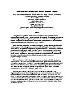
Relations between transmission objects are established by a connection between two or more ports. The MBS interpretation of a connection is a modeled physical interaction between two or more components, e.g., the direct physical contact of two bodies in one certain coordinate frame. This interconnection of several components is illustrated in Fig. 1 for a generic robotic structure. �
tool1
�
drive d3
joint r3
link l3
�
drive d2
joint r2
link l2
�
drive d1
joint r1
link l1
base
Fig. 1. Left: A generic 3 degree of freedom robot. Right: One possible corresponding graphical MBS model representation. The boxes depict transmission objects (joints, etc.), the grey squares the ports (narrow black rings), lines symbolize a (mechanical) connection.
To alleviate the modeling burden, higher level components, so-called assemblies, contain a hierarchy of aggregate connected primitive objects. In turn, this composition embodies the properties of a transmission. Along with the primitives, these assemblies are made available to the modeler as part of the domain library. In general, formalism migration, i.e., the continuous change in modeling primitives, is an important factor in the model integrated computing approach. However, in the robotics domain the set of primitives is not subject to much change. Therefore this issue is not discussed any further.
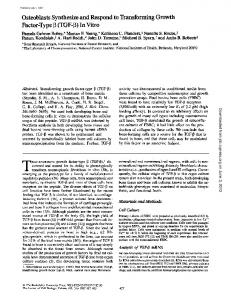
A. Static Semantics One of the goals of including domain specific constraints is to prevent the definition or modification of models from being not physical or not solvable. To this end, complementary connectors (’A’ and ’B’) are introduced that only permit connections between certain connectors of A and B type. Figure 2 shows the relations between all entities in the domain model in a UML-like class diagram [25]. Every transmission object is composed of a certain number of connector ports, where the A-typed are restricted to a number of two. This constrains the model graph to a directed tree-structure with restricted types of loops, as required by the Newton-Euler algorithm [14]. Note that there are (currently) two different types of connectors, frame and state. The first represents the contact of two or more components in one 3-dimensional coordinate frame, the latter a one-dimensional variant, e.g., for modeling drive-trains. Every transmission contains variables and parameters describing some of its distinct physical properties, e.g., the angle or the mass of a revolute joint. �
interface connector
frame
B-frame
connection
�
A-frame
0..n physical properties parameters variables
A-state
0..2
state
connection
B-state
0..n
Transmission object
�
assembly
interface transmission
DriveTrain d1(...); Link l1(...); RevoluteJoint r2(...); DriveTrain d2(...); Link l2(...); RevoluteJoint r3(...); DriveTrain d3(...); Link l3(...); ToolType1 tool1(...); ToolType2 tool2(...); /* connections */ base