Model-Integrated Programming Hubertus Franke IBM T.J. Watson Research Center Yorktown Heights, NY 10598
[email protected]
Abstract The building of complex, large-scale industrial applications necessitates the integration of models into the problem solving process. This paper describes a modelintegrated program synthesis environment for computerbased system applications. In Model-Integrated Program Synthesis (MIPS), domain-specific, multiple-view models represent the software, its environment and their relationships. Model interpreters translate the models into the input languages of static and dynamic analysis tools, and application specific model interpreters synthesize software applications. The components of the system are built in the framework of the layered Multigraph Architecture, which separates the generic and domain/application specific components, and defines interfaces for expandability.
1. Introduction One of the most significant developments in the last decade has been the proliferation of large-scale, complex computer integrated systems. In these systems, functional, performance and reliability requirements mandate a tight integration of physical and other processes with information processing. Important examples for systems where embedded information technology is critical for the overall system performance are: weapon systems, manufacturing systems, vehicles from cars to aerospace systems, patient management systems, transportation systems, and power generation and distribution systems. The increasing role of information technology in complex systems necessitates a substantial change in the engineering approach characterized by a shift from the conventional “discipline” and “life-cycle” orientation to an integrated “product/domain orientation”. This shift needs to be facilitated with new theories, methods, and tools to accelerate the progress in this important system category. The practice of using models in the full lifecycle of computer-based systems has been increasingly accepted. Multiple-aspect models are extensively used in requirement specification. Models are created and refined during design,
Janos Sztipanovits and Gabor Karsai Measurement and Computing Systems Lab Vanderbilt University Nashville, TN 37235 {sztipaj,gabor}@vuse.vanderbilt.edu
and they are used in the verification of the design. Systems engineering tools use models for performance, reliability and safety analysis. It is a general trend that design-time models are increasingly used during system operation for model-based monitoring, control and diagnostics. The tight integration of "physical" and "information" processes makes the application of a common description of these processes not only practical but mandatory. The common description means that software components are modeled as parts of the overall system, using concepts, relations and model structuring principles that are meaningful for the design and analysis of the whole system. Since computer-based systems are very multifarious, and software components play a rapidly increasing role in their operation, the modeling paradigms offered by conventional programming environments are not satisfactory. Typical programming environments support hierarchical structure and homogeneous decomposition [1] which is far from the heterogeneity and semantic richness of representations routinely used in many engineering domains. The challenge is to adopt domain specific, established modeling paradigms for representing software components, while preserving the capability of translating these models into executable code. The long term goal of our research at the Measurement and Computing Systems Laboratory of Vanderbilt University has been the development of a broadly applicable software technology for the design and implementation of complex, computer-integrated systems. The specific applications driving our research during the past decade have been: (a) on-line problem-solving environments for chemical plants, (b) fault detection, isolation and recovery (FDIR) systems for aerospace systems, (c) real-time facility monitoring and signal analysis for propulsion system testing, and (d) information systems for discrete manufacturing. Based on our experience, the recurring requirements in all these systems have been the tight conceptual relationships between the computer applications and their environment, the need for adapting the application/system to changing end-user requirements and operating conditions, cost sensitivity, and the stringent reliability and dependability criteria of military and
Proceedings of The Thirtieth Annual Hawwaii International Conference on System Sciences ISBN 0-8186-7862-3/97 $17.00 © 1997 IEEE
1060-3425/97 $10.00 (c) 1997 IEEE
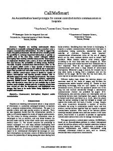
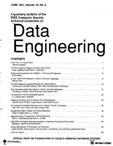
Figure 1: Abstraction Levels and of MGA (Multigraph Architecture)
industrial applications. Often these system consist of various subsystems that have to be integrated with each other and with external interfaces (e.g. data acquisition, real-time databases, operator interfaces, etc.). This integration process is often expensive and error prone. This paper discusses the model-integrated program synthesis component of the technology. In Model-Integrated Program Synthesis (MIPS), domain-specific, multiple-view models represent the software, its environment and their relationships. Model interpreters translate the models into the input languages of static and dynamic analysis tools, and application specific model interpreters synthesize software applications. Our framework for model-integrated program synthesis, the Multigraph Architecture (MGA), is discussed in Section 2. In Section 3, we summarize related efforts in model-based software synthesis. The overview of several MGA applications is provided in Section 4. The paper is concluded by looking at future research goals.
2. Multigraph Architecture Model-integrated program synthesis requires domain specific tools for: (1) building, testing, and storing models, (2) transforming the models into executable applications and/or extracting information for system engineering analysis tools, and (3) integrating applications on heterogeneous parallel/distributed computing platforms [2,3]. The high development cost of these tools would make their application prohibitive in many computer-based system applications. Therefore we have followed an architecture-based approach, which separates the generic
and domain/application specific components, and defines interfaces for expandability. The MGA has the following three levels of abstraction (see Figure 1):
2.1. Application Level The Application Level represents the synthesized software applications. The executable programs are specified in terms of the Multigraph Computational Model (MCM). The MCM is a macro-dataflow model which represents the synthesized programs as attributed, directed, bipartite graphs [3]. The MGK (Multigraph Kernel) is a runtime system for the model, and provides a unified system integration layer above heterogeneous computing environments including open system platforms, high performance, parallel/distributed computers and signal processors [2,4]. The elementary computations, which are scheduled by the MGK, are carefully defined, reusable code components that are part of application-specific run-time libraries. The MGK is implemented as an overlay above operating and communication systems. The MGK is supported on standard platforms (UNIX, WINDOWS-NT, WINDOWS-95, etc. operating systems and TCP/IP, MPI communication systems).
2.2. Model-Integrated Program Synthesis (MIPS) Level The MIPS Level includes generic, customizable, domain-specific tools for model building, model analysis, and application synthesis. The generic components of the
Proceedings of The Thirtieth Annual Hawwaii International Conference on System Sciences ISBN 0-8186-7862-3/97 $17.00 © 1997 IEEE
1060-3425/97 $10.00 (c) 1997 IEEE
architecture are the following: (1) customizable Graphical Model Builder (GMB) [5], (2) Object-Oriented Database (OODB) for storing and accessing models. The current version of GMB (called XVPE) is customized through the Editor Description Language (EDL) [5], which defines the modeling paradigm and the related graphical notations. The OODB is configured by means of the Object Description Language (ODL) of ODMG-93 database interface standard. The domain specific components include: (3) MGA analysis tools and external analysis tools, and (4) model interpreters that synthesize applications (executable models), or translate models into input data structures of the analysis tools (analysis models). Internal tools are designed for specific MGA-MIPS environments, and typically include a model interpreter, analysis algorithms and user interface. External tools are research tools that perform some static or dynamic analysis based on a domain independent abstract model. For example, the Stochastic Petri Net Package (SPNP) uses a domain independent modeling concept (Generalized Stochastic Petri Net) and analysis algorithms for performance analysis. An MGA model interpreter translates domain specific models into the input language of SPNP [6]. The MIPS level components are modular, and connected through standard interfaces (Figure 1). We have adopted the ODMG-93 standard for interfacing the model database to the GMB and to the model interpreters. This standard allows the use of OODB packages as model database. The Common Model Interface (CMI) is the specification of the object types of the given modeling paradigm forming a unified Tool-Software-Bus. (The CMI is the C++ header file generated by the schema translator of the OODB. This header file includes the class definition of the model objects accessible as persistent objects in the Model Database.) The MGA allows concurrent access to the Model Database by the GMB, and by various systems engineering analysis tools (and program synthesis tools). This is a necessity in largescale engineering problems where several engineering groups work concurrently on various aspects of the same system. From the operational point of view, the MIPS-level architecture is designed as a distributed object system, where the communicating "macro objects" are: GMB, OODB, and the Model Interpreters. For intertool communication, we have selected the CORBA standard. The domain specific MIPS environments are integrated tool suites supporting model building, model analysis, and program synthesis. In our experience, computer-based systems (e.g. aircrafts, manufacturing systems, chemical plants) are frequently dominated by some mature engineering discipline such as aerospace engineering, mechanical engineering, or chemical engineering. The modeling paradigms used for representing structural and behavioral aspects of these systems are "non-negotiable". The modeling tools must accommodate to the domain,
otherwise they lose relevance - and customers. Domain specific MIPS environments may differ from each other to a great extent. For example, the modeling paradigm (concepts, relationships, model composition principles and model integrity constraints) used in modeling the fault detection, isolation and recovery properties of the International Space Station Alpha (ISSA) (one of the MGA applications, described [7]) is completely different from that one used in modeling chemical plants, processes, and problem solving activities [8]. Similarly, the model interpreter used for synthesizing real-time diagnostic systems is quite different from the one synthesizing an embedded process simulation. MIPS environments change not only across domains, but they must evolve inside a domain as well. For example, as the modeling effort progressed in the ISSA program, accumulated insight and increased understanding triggered several major revisions in the modeling paradigm. The environment and the models must evolve with these changing concepts, because the models represent a significant investment. Our challenge has been to create a software infrastructure, which enables the inexpensive construction of reliable domain specific MIPS environments, and provides efficient support for their evolution.
2.3. Meta-Level The third level of the MGA is a metaprogramming interface providing: (a) support for the specification of domain-specific modeling paradigms and model interpreters using a declarative language, (b) meta-level translators to generate configuration files for the GMB and OODB from the modeling paradigm specification, and (c) tools for writing model interpreters. The metaprogramming interface introduces an additional level of abstraction in MGA. The central concepts are meta-models (models of models), which are the specifications of modeling paradigms and model interpreters. The meta-models define the semantics of domain specific modeling languages [5]. The semantics of modeling paradigms are defined by the constraints within the domain models with respect to the concepts, relations, model composition principles and domain-specific integrity constraints. In this approach, applications are "executable instances" of domain models and the domain models are "instances" of meta-models. Currently MGA has a simple, preliminary version of the metaprogramming interface which is not satisfactory due to the following problems: (1) We use a declarative language for defining modeling paradigms. This language is not rich enough to provide a rigorous, concise specification for complex model semantics. (2) The currently used formalism does not support the validation of complex paradigms. (3) There is no support for the formal specification of the
Proceedings of The Thirtieth Annual Hawwaii International Conference on System Sciences ISBN 0-8186-7862-3/97 $17.00 © 1997 IEEE
1060-3425/97 $10.00 (c) 1997 IEEE
semantics of the model interpreters and execution environments. Consequently, validation and verification of model interpreters and execution environments is relatively difficult and requires in-depth knowledge of the technology. Finding solutions for these problems is one of our active research areas.
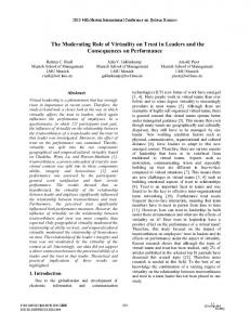
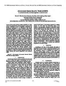
2.4. Model-based program synthesis A key characteristic of the MGA is its support for the synthesis of applications from models. Program synthesis is performed by the model interpreters. Figure 2 shows the elements of the model interpretation process with a single interpreter. Complex systems consisting of several integrated applications are typically generated by multiple model interpreters - one for each component application but using the same integrated model set.
Figure 2: Model interpretation in MGA During application synthesis, the model interpreter traverses the model database from the root of the model hierarchy. It incrementally builds the actual executable system in the MGK environment using the "Builder Interface" of the MGK by creating and connecting the elementary components of the MGK processing network (actor and data nodes) [2]. Parallel with the executable system, the model interpreter also creates a "builder object network". The relationship between the builder object network and the models is determined by the model composition principles. For example, in modeling paradigms employing a hierarchical module interconnection composition method, there is one builder object for each compound and primitive module in the model hierarchy. The builder objects have three roles. (1) They store references to the appropriate objects and levels in the model database. (2) They store references to all the components of the MGK processing network (actor and data nodes) that are relevant to the given level of the hierarchy. (3) They
maintain connections to the processing network for receiving events that trigger reconfiguration. In most of our applications, the model database, model interpreters and the builder object network are in one process (and computing node), while the component applications are synthesized in separate processes (running on the same, or different computing nodes). The execution environment is decoupled from the modeling environment to maintain real-time behavior. The model interpreter accesses the model database through the transaction mechanisms of the OODB (as defined by the ODMG’93 standard). After the synthesized application started, it runs under the control of MGK. The MGK schedules the elementary computations according to the graph topology defined, and according to the control principle (if-any or if-all) of the elementary nodes. Re-synthesis can be triggered by the user (after changing the model some way) or by the application (after detecting a significant event requiring changes in the structure of the executing system). User-initiated changes are typically the result of incremental changes in the models, and therefore correspond to evolutionary system behavior. The changes triggered by events in the execution system are typically fast reactions to detected changes in the environment (e.g. sensor failure), therefore this behavior can be considered structural adaptation [3]. During resynthesis of the application, the model interpretation restarts from a particular level of the model hierarchy (identified by a builder object). The interpreter builds a new version of the processing network through the builder interface (without suspending the rest of the application) and the builder object network. Using an MGK control protocol [2], the interpreter switches over from the old version of the processing network to the new computational structure. The programming language used for implementing the elementary computation modules (i.e. the run-time library for the execution environment) has impact on the capability for reconfiguration. In static languages, such as C and C++, the MGK, and all relevant low-level computation primitives are linked together and form an MGK-C or MGK-C++ process. Through the builder interface, the model interpreters are able to modify data structures and the graph topology using the pre-linked primitives, but cannot dynamically add computational primitives. Using dynamic languages supporting late binding and dynamic linking/loading, MGK processes can be created that allow the upgrading of the low-level primitives as well. In earlier MGA implementations this capability was provided in LISP environments. It is one of our goals to create and evaluate the performance of an MGK environment using one of the modern dynamic languages, such as Java or Dylan.
Proceedings of The Thirtieth Annual Hawwaii International Conference on System Sciences ISBN 0-8186-7862-3/97 $17.00 © 1997 IEEE
1060-3425/97 $10.00 (c) 1997 IEEE
2.5. Software Engineering Process with MGA In the three-level architecture described above, the following three user groups are identified: (1) end-users, interacting with the synthesized applications through operator interfaces, (2) domain engineers, (and possibly end-users) using customized MIPS environments to create, modify models and to evolve, adapt applications, and (3) a small group of software/systems engineers designing and building domain specific MIPS environments by means of the meta-level tools of the MGA [18]. The type of activities, the required expertise, and the characteristics of the tools is strongly different for these user groups.
with model building, and forms an iterative process. Step 3: Application synthesis. Models are processed by application specific model interpreters that synthesize the applications. In model-integrated program synthesis there is no major difference between "fast prototyping" and rapid-implementation: the generated software is production quality. The support for dynamic (incremental) application synthesis allows iterations, refinements in the models and in the generated applications even after post deployment. Step 4: System integration. Since different applications are built by their respective models interpreters using the same integrated model set, system integration is a highly automatic process which is merged with Step 3.
I. Building MIPS Environments Step 1: Specification and validation of the modeling paradigm: This step requires understanding the concepts, relationships, model composition principles, and integrity constraints of the domain. This phase is supported by the metaprogramming interface of MGA. Step 2: Customization of the GMB and the model database: This step is completed by meta-level translators generating the configuration file of the GMB, the ODL representation of the database schema, and the OODB-GMB interface code. Step 3: Specification, validation and implementation of model interpreters: This step requires understanding the relationship between domain models and the application category to be synthesized. The current version of the metaprogramming interface includes only limited support for writing model interpreters. Step 4: Design and implementation of run-time libraries for each application category. Typical run-time libraries are composed of software modules of subroutine-size, with standard interfaces to the Multigraph Kernel.
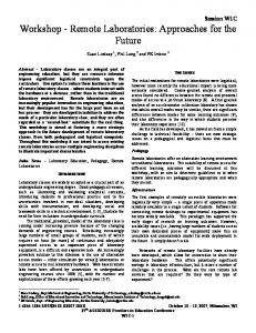
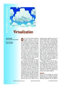
The traditional software development process consist of several well defined phases: requirement analysis, specification, implementation, integration, testing and maintenance. Based on a study [19], the significant portions of software errors originate in the analysis and design phase. Consequently requirement analysis and specification are the most demanding phases of the software cycle. In MIPS these phases are coupled, for instance models are consistent and incremental system changes “merely” require a reinterpretation. Figure 3 illustrates the benefits of employing ModelIntegrated Programming Systems through out the life cycle of software development over traditional approaches. To summarize, one can expect to increase productivity, maintainability, reusability, documentation and ultimately the number of users of a system.
Conventional Software Engineering Approach and inherent Error Sources Subsyste m # 1
Req. A naly.
II. Building Applications
Design
SW Impl
M odel
Step 1: Building domain specific models. Using the customized GMB model building tool, domain engineers build multiple-view models of systems to be synthesized. Step 2: Verification and validation of models. Applications are synthesized from the information captured in the domain models. Currently, we use two methods for model verification and validation. Static model checking tests the models against certain consistency and model integrity criteria. Static model checking is done partially during model building and partially during model interpretation. Dynamic model checking requires simulation and performance evaluation tools that are part of a MIPS tool suite (see examples in [7]). Verification and model validation is tightly integrated
Integr.
M aint.
In t eg ra ti on Errors due to in c o m p at i b le Des ign
High Cost
Subsyste m # n
Req. Analy.
Modeling Error s
F a ul ty Analys is
Graphic al Edit or Validation Tools
Design
Wrong D es ig n Dec is ions
Domain Conc ept s Automatic Code Generation
SW Impl
Coding E rrors
Au to ma tic Sys tem Integration
Model Up date
Benefits of M I P S
Figure 3: Benefits of Model-Integrated Programming from a Software Engineering Perspective
Proceedings of The Thirtieth Annual Hawwaii International Conference on System Sciences ISBN 0-8186-7862-3/97 $17.00 © 1997 IEEE
1060-3425/97 $10.00 (c) 1997 IEEE
System
Domain
Function
Platform
Difficulty
MGA-DTOOL
aerospace systems
modeling and diagnosability analysis
SUN and HP700 workstations
Complexity of modeling paradigm and size of models
MGA-RDS
aerospace systems
MIPS for robust, real-time SUN and HP700 diagnostics workstations
Complexity of modeling paradigms and model interpreters
IPCS
chemical plants
on-line problem solving environment for process management
HP700 workstations
Complexity of modeling paradigms and heterogeneity of synthesized applications
CADDMAS
dynamic data real-time vibration analysis of analysis turbine/ rocket engines
heterogeneous network of PC-s and over 100 TITMSC40 and C31 signal processors
Complexity of the synthesized parallel applications
DATVAL
turbine engine model-based sensor data testing validation
SGI workstation network
Relationship to legacy systems
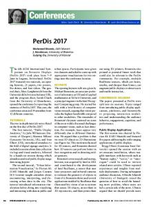
Table 1: Selected MGA Applications
3. Related Work Our research shares ideas and builds on results of several important directions in software engineering. Here, we only discuss those research areas whose objectives have essential commonalities with ours. The significance of using models in software engineering is well explained and demonstrated by Harel [9]. The model-based approach has become a particularly rich, productive research area in object-oriented software engineering and has already made significant impact on today’s software engineering [10]. One of the fundamental goals of the research is to identify general modeling paradigms to be used in the design and analysis of complex systems. Different approaches are proposed for modeling functional structure, static and dynamic behavior, physical structure, inter-object communication using multiple views [10], finite state machines [11], etc. The MGA approach is profoundly different from the object modeling methods. The modeling paradigm is customizable, which may or may not include specialization/generalization. The relationship between the model objects and the run-time objects (the synthesized application) can be very complex - as determined by the solution strategy which is captured by the model interpreters. From the same model set, many applications can be generated by means of different model interpreters. The differences do not mean that MGA-based MIPS environments do not take advantage of the object technology. In fact, object-oriented programming and object
modeling is extensively used in the implementation of MGA tools. The increased emphasis on software architectures has stimulated considerable amount of work on Architecture Description Languages (ADL). ADL-s focus on the higher-level structural representation of applications, allowing programmers to design and analyze the overall structure of applications without dealing with the implementational details of software modules. The Domain Specific Software Architecture (DSSA) program of ARPA underlined the significance of domain specific ADL-s offering semantic models, notational conventions directly relevant to a domain. Examples for results on software architectures include the introduction of the concept of architectural styles and classification of software architectures [12], and ADL-s such as Rapide [13], MetaH/ControlH [14], and Onika/Chimera [15]. MGA does and will benefit from these results in many ways and has similarities to individual approaches and methods.
4. Applications There are several major, existing applications of model integrated computing and MGA in the aerospace and manufacturing industries. A summary of selected MGA applications developed in the past 4 years are shown in Table 1.
Proceedings of The Thirtieth Annual Hawwaii International Conference on System Sciences ISBN 0-8186-7862-3/97 $17.00 © 1997 IEEE
1060-3425/97 $10.00 (c) 1997 IEEE
4.1. MGA-DTOOL/MGA-RDS: A Model-Based Engineering Environment for FDIR in Aerospace MGA is the software framework of a model-based robust diagnostic system (MGA-RDS) and diagnosability/test ability analysis tool (MGA-DTOOL) used by the Boeing Company in the International Space Station Alpha (ISSA) Program. In this application, the multiple-view modeling environment supports the functional, physical, and behavioral modeling of ISSA system components. Additional modeling views support the representation of fault detection activities and operator communication schemes. Tools of the modeling environment allow graphical model building, support extensive model consistency checking, and provide interfaces to related models, such as FMEA models available in engineering databases. The system has several model interpreters. The model interpreter for the Diagnosability/Testability Analysis Tool [16] extracts relevant information from the multiple-view models and synthesizes data structures required by DTOOL. DTOOL evaluates detectability, distinguishability, and predictability of faults given on-line sensor allocation and built-in-test (BIT) coverage, generates optimum test sequences, and provides advice for additional sensors/BIT coverage to meet defined criteria. A different family of model interpreters automatically generates executable code for the real-time diagnostic system from the same integrated model-set, allowing significant savings in system/software engineering time. Details of this application are described in a companion paper [7].
4.2. Problem Solving Environment for Chemical Industry The Intelligent Process Control System (IPCS) is an online problem solving environment and decision support tool for process and production management. The central concepts of IPCS are models of the plant and process engineering activities. Plant models include a variety of modeling views, including process flow sheets, static and dynamic process equations, finite state models, failure propagations, equipment structure, etc. Activity models cover a wide range of tasks related to process and production management, such as analysis of process operation, diagnosis of process faults, testing and modifying control strategies and others. These activities extensively utilize plant and process information which is represented in plant models, and access to the available process monitoring and control functionalities, such as process historian and DCS. Activity models may include explicit references to the utilized plant model elements and the specification of logical and physical interfaces to other software packages
which implement different monitoring and control functionalities. The activity models are automatically translated into executable software by IPCS, which performs the modeled activity. The IPCS system is actively used at Du Pont Old Hickory, TN plant for the development of commercial applications, including monitoring, sensor data validation, on-line process simulation, and process diagnosis [8].
4.3. CADDMAS: Computer Assisted Dynamic Data Monitoring and Analysis System MGA is the underlying software technology for the Computer Aided Dynamic Data Monitoring System (CADDMAS) developed in close cooperation with the USAF Arnold Engineering and Development Center (AEDC). CADDMAS provides real-time vibration analysis for 48 channels of 50 kHz bandwidth using a heterogeneous network of nearly 100 processors [2,17]. Different versions of the CADDMAS are now being applied as primary online test systems in the turbine engine testing facilities of AEDC. The 50 kHz bandwidth CADDMAS, which has been recently completed, provides 2 GFlops computation throughput. In the CADDMAS application, the MGA modeling environment supports the hierarchical modeling of signal flow graphs, hardware resources, and resource limitations [2]. A model interpreter synthesizes the complex executable program and configures the parallel computing platform. Several other model interpreters generate input data for analyzer tools. For example, one of the interpreters generates a Stochastic Petri Net (SPN) model of the executable system. It is evaluated by a SPNP solver, providing performance evaluation of the system before its actual implementation [6].
4.4. DATVAL: Data Validation System for Turbine Engine Testing A model-based, real-time data validation system is under development using MGA, which detects anomalies in sensor data and isolates the most plausible source of faults. The data validation system utilizes massive amount of information about the test article and the testing facility. The modeling paradigm of the full system will include multiple view models of the facility, the test article, and will configure the real-time validation program on a distributed workstation network.
5. Conclusion Model-integrated programming seems to be an important component of the technology of computer-based systems. The basic idea is to represent these systems by
Proceedings of The Thirtieth Annual Hawwaii International Conference on System Sciences ISBN 0-8186-7862-3/97 $17.00 © 1997 IEEE
1060-3425/97 $10.00 (c) 1997 IEEE
means of domain specific modeling paradigms tailored to the characteristics of the system and not to the implementation techniques of its components. Carefully designed modeling paradigms facilitate the analysis of system-wide properties which are the most interesting aspects of this system category. Model-integrated program synthesis generates applications directly from domain models drastically reducing software cost. The applications showed the following advantages: •
•
•
Modeling paradigm specifications and domain models quickly become a valuable asset. The technology enables many different forms of interaction, communication, and commercial endeavor with the models. Maintained models of manufacturing processes help industry to conform to environmental regulations (e.g. chemical industry) and allow keeping problem solving activities consistent with the changing/ evolving plants. Model-integrated programming environments are effective tools for teaching problem solving strategies. Technical difficulties related to using, integrating, and managing large software systems do not avert students from focusing on problems instead of collateral technical issues.
Besides building new integrated environments in a wide range of application domains, our current effort focuses on the development of an advanced meta-programming interface, which will support formal verification of modeling paradigms and model interpreters.
References [1]
[2]
[3]
[4]
[5]
Michael Jackson: "The World and the Machine," Proc. of the 17th International Conference on Software Engineering, pp. 283-292, Seattle, WA. April 23-30, 1995. Abbott, B., Bapty, T., Biegl, C., Karsai, G., Sztipanovits, J.: "Model-Based Approach for Software Synthesis," IEEE Software, pp. 42-53, May, 1993. Sztipanovits, J., Wilkes, D., Karsai, G., Biegl, C., Lynd, L: "The Multigraph and Structural Adaptivity," IEEE Transactions on Signal Processing, Vol. 41, No. 8., pp. 2695-2716, 1993. Karsai, G., Sztipanovits, Padalkar, S., Biegl, C., J., Okuda, K., Miyasaka, N: "Model-Based Intelligent Process Control for Cogenerator Plants," Journal of Parallel and Distributed Computing, Vol. 15, No. 6. Karsai, G.: "A Visual Programming Environment for Domain Specific Model-Based Programming," IEEE Computer, pp. 36-44 March 1995.
[6]
Childers, C.A., Apon, A.W., Hooper, W.H., Gordon, K.D., Dowdy, L.W.: "The Multigraph Modeling Tool", Proc. of the 7th International Conference on Parallel and Distributed Systems, Las Vegas, Nevada, October 5-8, 1994. [7] Carnes, R.J., Misra, A., Sztipanovits, J.: "ModelIntegrated Toolset for Fault-Detection, Isolation and Recovery (FDIR)", in this proceedings [8] Karsai, G., Sztipanovits, J., Franke, H., Padalkar, S., Decaria, F: "Model-Embedded Problem Solving Environment for Chemical Engineering," Proc. of IEEE IECCS’95, pp. 227-234, Florida, 1995. [9] Harel, D.: “Biting the Silver Bullet,” IEEE Computer, pp.8-20, January, 1992. [10] Booch, G.: Object Oriented Analysis and Design with Applications, Benjamin/Cummings, 1994. [11] Harel, D., et.al.: “STATEMATE A working Environment for the Development of Complex Reactive Systems,” IEEE Trans. On Software Engineering, April 1990, Vol. XVI, No. 4. [12] Shaw, M.: “Comparing Architectural Design Styles,” IEEE Software, pp. 27-41, November, 1995. [13] Luckham, D.C., Vera, J.: “An Event-Based Architecture Definiton Language,” IEEE Trans. on Software Engineering, Vol. 21, No. 9., pp. 717-734, September, 1995. [14] Binns, P., Englehart, M., Jackson, M., Vestal, S.: “Domain-Specific Software Architecture for Guidance, Navigation and Control,” International Journal of Software Engineering and Knowledge Engineering, 1995. [15] Gertz, M.W., Stewart, D.B., Khosla, P.K.: “A Human-Machine Interface for Distributed Virtual Laboratories,” IEEE Robotics and Automation Magazine, December, 1994. [16] Misra, A., Sztipanovits, J., Underbrink, A., Carnes, R., Purves, B.: “Diagnosibility of Dynamical Systems,” Proc. Of the Third International Workshop on Principles of Diagnosis, pp. 239-244, Rosario, WA 1992. [17] Ledeczi, A., Bapty, T., Karsai, G., Sztipanovits, J.: “Modeling Paradigm for Parallel Signal Processing,” The Australian Computer Journal, vol. 27, No.3, pp. 92-102, August, 1995. [18] Franke, H.: “PREMOS: Tools for Model-based Programming,” Ph.D. Thesis, Department of Electrical Engineering, Vanderbilt University, 1992. [19] Fisher, A.: “CASE: Using Software Development Tools”, John Wiley & Sons, 1988.
Proceedings of The Thirtieth Annual Hawwaii International Conference on System Sciences ISBN 0-8186-7862-3/97 $17.00 © 1997 IEEE
1060-3425/97 $10.00 (c) 1997 IEEE