Obm. Ocm. Od γ. 1-γ. Tr. Tr γ. 1-γ. Tr. Tr. 1. Fig. 3. General Markov chain model of the slotted CSMA-CA algorithm representing a non-idle state of the node.
Modeling a Beacon Enabled 802.15.4 Cluster with Bidirectional Traffic Jelena Miˇsi´c� , Shairmina Shafi, and Vojislav B. Miˇsi´c Department of Computer Science, University of Manitoba, Winnipeg, Canada
Abstract. We analyze the performance of an IEEE 802.15.4 compliant network cluster operating in the beacon enabled mode with both downlink and uplink traffic. We investigate the non-saturation regime and outline the conditions under which the network abruptly goes to saturation. The operation of the WPAN is modeled through discrete time Markov chains and the theory of M/G/1 queues. The model considers acknowledged transmissions and includes the impact of different network and traffic parameters such as the packet arrival rate, packet size, inactive period between the beacons, and the number of stations. We analyze the stability of the network queues and show that the stability of the downlink queue at the coordinator is the most critical for network operation.
1
Introduction
The success of wireless sensor networks as a technology rests on the success of the standardization efforts to unify the market and avoiding the proliferation of proprietary, incompatible protocols that, although, perhaps optimal in their individual market niches, will limit the size of overall wireless sensor market [1]. The recent IEEE 802.15.4 standard for low rate wireless personal area networks is considered as one of the technology candidates for wireless sensor networks [2, 1] since it supports small, cheap, energy-efficient devices operating on battery power that require little infrastructure to operate, or none at all. In an IEEE 802.15.4-compliant WPAN, a central controller device (commonly referred to as the PAN coordinator) builds a WPAN with other devices within a small physical space known as the personal operating space. Two topologies are supported: in the star topology network, all communications, even those between the devices themselves, must go through the PAN coordinator. In the peer-to-peer topology, the devices can communicate with one another directly – as long as they are within the physical range – but the PAN coordinator must be present nevertheless. The standard also defines two channel access mechanisms, depending on whether a beacon frame (which is sent periodically by the PAN coordinator) is used to synchronize communications or not. Beacon �
This research is partly supported by the NSERC Discovery Grant.
R. Boutaba et al. (Eds.): NETWORKING 2005, LNCS 3462, pp. 228–239, 2005. c IFIP International Federation for Information Processing 2005 �
Modeling a Beacon Enabled 802.15.4 Cluster with Bidirectional Traffic
229
enabled networks use slotted carrier sense multiple access mechanism with collision avoidance (CSMA-CA), while the non-beacon enabled networks use simpler, unslotted CSMA-CA. In this work, we model the 802.15.4 sensor network (cluster) with downlink and uplink transmissions, which operates in beacon-enabled mode with slotted CSMA-CA communication. This setting corresponds well to sensing applications with hierarchical topology wherein individual nodes communicate with the PAN (cluster) coordinators only. The goal of this work is to evaluate the performance of such networks, identify possible performance bottlenecks and quantify their impact. We combine the theory of discrete-time Markov chains and the theory of M/G/1 queues to derive the probability distributions of packet service times, which is then validated through simulation. We also derive the stability limits of individual queues. To the best of our knowledge, this is the first analytical model of 802.15.4 networks with bidirectional traffic; the only other paper that considers the similar problem [4] is based exclusively on simulation results. The current work significantly extends our previous work on uplink channel modeling [5] in which downlink data transmissions were not considered at all. The paper is organized as follows. Section 2 explains some basic features of the 802.15.4 MAC, including the CSMA-CA algorithm. Section 3 describes the analytical model of the MAC layer, which is then used to model the behavior of a complete node in Sect. 3.1. Section 4 presents and discusses the results of our analysis. Section 5 concludes the paper.
2
Basic Properties of the 802.15.4 MAC
In beacon enabled networks, the channel time is divided into superframes which are bounded by beacon transmissions from the coordinator, as shown in Fig. 1 [3]. All communications in the cluster take place during the active portion of the superframe, the duration of which is referred to as the superframe duration SD. During the (optional) inactive portion, nodes may enter a low power mode, or engage in other activities at will. The active portion of each superframe is divided into equally sized slots; the beacon transmission commences at the beginning of slot 0, and the contention access period (CAP) of the active portion starts immediately after the beacon. Slots are further subdivided into backoff periods, the basic time units of the MAC protocol to which all transmissions must be synchronized. The actual duration of the backoff period depends on the frequency band in which the 802.15.4 WPAN is operating: 868 to 868.6MHz, 902 to 928MHz, or 2400 to 2483.5MHz [3]. The maximum data rates for these bands are 20kbps, 40kbps, and 250kbps, respectively. A part of the active portion of the superframe may be reserved by the PAN coordinator for dedicated access by some devices; this part is referred to as the contention-free period (CFP), while the slots within are referred to as the
230
J. Miˇsi´c, S. Shafi, and V.B. Miˇsi´c contention-access period (CAP)
beacon
contention-free period (CFP) guaranteed time slots (GTS)
0
1
2
3
4
5
6
7
8
9
beacon
inactive
10 11 12 13 14 15
superframe duration (SD) beacon interval (BI)
Fig. 1. The composition of the superframe under IEEE Std 802.15.4 (adapted from [3])
guaranteed time slots (GTS). In this work we do not consider the GTS, although their presence will clearly decrease the usable bandwidth of the PAN for other devices. 2.1
The CSMA-CA Algorithm
During the CAP period, individual nodes access the channel using the CSMACA algorithm. The algorithm begins by initializing i to zero and c to 2; the variable i = 0 . . m (where m = macMaxCSMABackoff − 1) represents the index of the backoff attempt, while the variable c = 0, 1, 2 represents the index of the Clear Channel Assessment (CCA) phase counter. Note that the standard denotes these variables with N B and CW , respectively [3]; we use different notation in order to simplify the mathematical expressions in our model. If the device operates on battery power, as indicated by the attribute macBattLifeExt, the parameter BE (the backoff exponent which is used to calculate the number of backoff periods before the node device attempts to assess the channel) is set to 2 or to the constant macMinBE, whichever is less; otherwise, it is set to macMinBE (the default value of which is 3). The algorithm then locates the boundary of the next backoff period; as mentioned above, all operations must be synchronized to backoff time units. In step (2), the algorithm generates a random waiting time k in the range 0 . . 2BE − 1 backoff periods. The value of k is then decremented at the boundary of each backoff period. Note that the counter will be frozen during the inactive portion of the beacon interval, and the countdown will resume when the next superframe begins. When this counter becomes zero, the device must make sure the medium is clear before attempting to transmit a frame. This is done by listening to the channel to make sure no device is currently transmitting. This procedure, referred to as Clear Channel Assessment (CCA), has to be done in two successive backoff periods. If the channel is found busy at the second CCA, the algorithm simply repeats the two CCAs starting from step (3). However, if the channel is busy at the first CCA, the values of i and BE are increased by one, while c is reset to 2, and another random wait is initiated; this is step (4) in the flowchart. In this case, when the number of retries is below or equal to macMaxCSMABackoffs (the default value of which is 5), the algorithm returns to step (2), otherwise it terminates with a channel access failure status. Failure will be reported to the
Modeling a Beacon Enabled 802.15.4 Cluster with Bidirectional Traffic
231
higher protocol layers, which can then decide whether to re-attempt the transmission as a new packet or not. In our model, we assume that the transmission will be re-attempted until the final success. If both CCAs report that the channel is idle, packet transmission may begin. Before undertaking step (3), the algorithm checks whether the remaining time within the CAP area of the current superframe is sufficient to accommodate the CCAs, the data frame, the proper interframe spacing, and the acknowledgment. If this is the case, the algorithm proceeds with step (3); otherwise it will simply pause until the next superframe, and resume step (3) immediately after the beacon frame. 2.2
On Uplink and Downlink Communication
According to the 802.15.4 standard, uplink data transfers from a node to the coordinator are synchronized with the beacon, in the sense that both the original transmission and the subsequent acknowledgment must occur within the active portion of the same superframe, as shown in Fig. 2(a). Uplink transmissions always use the CSMA-CA mechanism outlined above. Data transfers in the downlink direction, from the coordinator to a node, are more complex, as they must first be announced by the coordinator. In this case, the beacon frame will contain the list of nodes that have pending downlink packets, as shown in Fig. 2(b). When the node learns there is a data packet to be received, it transmits a MAC command requesting the data. The coordinator acknowledges the successful reception of the request by transmitting an acknowledgement. After receiving the acknowledgement, the node listens for the actual data packet for the period of aMaxFrameResponseTime, during which the coordinator must send the data frame. network device
coordinator network device
coordinator
Beacon Beacon
Data Request Acknowledgment
Data
Data
(optional) Acknowledgment
Acknowledgment
(a) Uplink transmission.
(b) Downlink transmission.
Fig. 2. Uplink and downlink data transfers in beacon enabled PAN
According to the standard, it is allowed to send the data frame ‘piggybacked’ after the request acknowledgment packet, i.e., without using CSMACA. However, two conditions have to be fulfilled: the coordinator must be able
232
J. Miˇsi´c, S. Shafi, and V.B. Miˇsi´c
to commence the transmission of the data packet between aTurnaroundTime and aTurnaroundTime + aUnitBackoffPeriod, and there must be sufficient time in the CAP for the message, appropriate inter-frame spacing, and acknowledgement; if either of these is not possible, the data frame must be sent using the CSMA-CA mechanism [3]. While the first condition depends on the implementation platform, the second depends on the actual traffic; thus some data frames will have to be sent using CSMA-CA. For uniformity, our model adopts a more generic approach by assuming that slotted CSMA-CA is used for all downlink transmissions, although the case where CSMA-CA is not used could be accommodated with ease. Furthermore, downlink transmissions that do not use the CSMA-CA mechanism would cause additional collisions and thus lead to the deterioration of network performance. While the use of acknowledgment is optional (i.e., it is sent only if explicitly requested by the transmitter), in this work we assume that all the transmissions are acknowledged. In this case, the receiving node must acknowledge successful reception of the data frame within a prescribed time interval, otherwise the entire procedure (starting from the announcement through the beacon frame) has to be repeated. According to the Section 7.5.6.4.2 of the 802.15.4 standard [3], the transmission of an acknowledgement frame shall commence at the backoff period boundary between aTurnaroundTime and aTurnaroundTime + aUnitBackoffPeriod after the data frame, which amounts to a delay of 12 to 32 symbol periods. Since one backoff period takes 20 symbols, this time interval may include at most one backoff period at which the channel will be assessed idle. However, a node that has finished its random countdown will need at least two CCAs before attempting transmission: while the first one may find the medium idle in between the data frame and the acknowledgment, the second one will coincide with the acknowledgment and cause the CSMA-CA algorithm to revert to the next iteration of the backoff countdown. Consequently, the acknowledgment packet cannot possibly collide with the data packet sent by another node. It should be noted that the Section 7.5.6.7 of the standard stipulates that the data packet originator should wait for an acknowledgment for at most macAckWaitDuration, which amounts to 54 or 120 symbols, depending on the actual channel number. If the acknowledgment packet is not received within macAckWaitDuration after the original data frame, the originator may safely assume that the frame has been lost and initiate re-transmission. 2.3
Operational States
From the discussions presented above, the following states can be identified for the PAN coordinator node: 1. The coordinator may be transmitting the beacon. 2. The coordinator may be listening to its nodes and receiving data or request packets.
Modeling a Beacon Enabled 802.15.4 Cluster with Bidirectional Traffic
233
3. The coordinator may be transmitting the downlink data packet as a result of previously received request packet. As soon as downlink transmission is finished coordinator switches to the listening mode. Similarly, an arbitrary (non-coordinator) node in the cluster can be in one of the following states: 1. The node may be transmitting an uplink data packet. 2. The node may be transmitting an uplink request packet. 3. The node may be in an uplink request synchronization state, which is a virtual state that lasts from the moment of new downlink packet arrival at the coordinator (or the failure of the previous downlink reception) up to the beginning of the CSMA-CA procedure for the uplink request. Note that the arrivals of downlink packets at the coordinator follow the Poisson process, whereas the corresponding announcements in the beacon (from which the target node finds out about those packets) do not. 4. The node may be waiting for a downlink packet. 5. The node may also be in an idle state, without any downlink or uplink transmission pending or in progress.
3
Basic Analytical Model
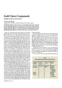
Since the same CSMA-CA algorithm is used for uplink data transmission, uplink request transmission and downlink data transmission, we will model this algorithm first, and then use it as a building block to model the operation of the node. The MAC parameter BO (which stands for macBeaconOrder ) determines the period between the beacons as BI = 2BO aBaseSuperframeDuration. For simplicity we assume that BO has a constant value of zero, in which case the superframe duration is SD = aBaseSuperframeDuration; the extension of the model to accommodate different lengths of the superframe is straightforward. Note that the beacon interval and the duration of the superframe are determined by the energy management policy of the network; however, issues related to energy management are beyond the scope of the present work. The discrete-time Markov chain for the 802.15.4 CSMA-CA algorithm is presented in Figs. 3 and 4. The ‘delay line’ models the case in which the remaining time within the superframe does not suffice for two CCAs, packet transmission, and reception of the acknowledgment. We assume that this Markov chain, together with the higher level structure into which it is incorporated, has stationary distribution. The process {i, c, k, d} defines the state of the device at backoff unit boundaries. Note that the last tuple member d denotes the index of the state within the delay line mentioned above; in order to reduce notational complexity, it will be shown only within the delay line and omitted in other cases, where its value is, in fact, undefined. Transitions between the states on Fig. 3 depend on several probabilities. First, all transitions occur at the edge of the aUnitBackoffPeriod. α is the probability
234
J. Miˇsi´c, S. Shafi, and V.B. Miˇsi´c In uniformly distributed among the W 0 states
0,2,W 0-1
1
0,2,W 0-2
1
0,2,1
Pd,0
0,2,0
(1-Pd,0)(1-α)
(1-Pd,0)α "delay line" 0
0,1,0 1-β β
1 γ
0,0,0
1-γ uniformly distributed among the W m states
m,2,W m-1
1
m,2,W m-2
1
m,2,1
Tr
Ob0 Oc0
Pd,m
m,2,0
(1-Pd,m)(1-α)
Tr
(1-Pd,m)α "delay line" m
m,1,0 1-β β
1
m,0,0 m+1,0,0
γ 1-γ
1
Tr Tr
Obm Ocm
Od
CSMA-CA Markov Chain building block
Fig. 3. General Markov chain model of the slotted CSMA-CA algorithm representing a non-idle state of the node Pd,i 1
_
_
Dd-2
i,2,0,Dd-1
1
1
_
_
Dd-3
i,2,0,Dd-2
1
1 i,2,0,1
1 0
Tr
1 i,2,0,0
1
Pd,i / Dd
_ Pd,i / Dd
1
1 1
_
"delay line" i
_ Pd,i / Dd
_ Pd,i / Dd
1
Fig. 4. Delay lines for Fig. 3
that medium is idle on the first CCA while β is the probability that medium is idle on second CCA. γ is the probability that transmission will be successful and Pd,i is the probability that after i-th backoff attempt there will be no space
Modeling a Beacon Enabled 802.15.4 Cluster with Bidirectional Traffic
235
Uplink Request Synchronization
λid
Pda
ρd Oc0 Oc1 Ocm Od
(1-λiu)(1-λid) 1-ρd
idle state node i
In
(1-ρud)(1-Pda)
Ob0 Ob1
λiu(1-λid)
Obm
Uplink Request (node i )
blocked requests M/G/1/1
ρud(1-Pda) switch to TX
In
Oc0 Oc1
switch to TX
switch to RX
Oc0 Oc1
Ocm Od
Ocm Od
Ob0 Ob1
Ob3 Ob4
Obm
Obm
In
Ob0
Uplink Data (node i )
PAN Coordinator, Downlink Data
Fig. 5. Markov chain model of a node
in the current superframe to conduct two CCAs and transmission. Due to the lack of space we don’t present the equations which correspond to this Markov chain. 3.1
Markov Chain Model for a Node
Let us now consider a cluster with n identical devices. The packet queues in the device data buffer and request buffer are modeled as a M/G/1 queueing system, in which the packet request queue has non-preemptive priority over the data queue at the device. Both uplink and downlink packet arrivals follow a Poisson process with the average arrival rate of λiu and λid , respectively. Fig. 5 shows the high-level states of a network node – namely, the idle state, uplink data transmission, uplink request transmission and waiting for downlink data from the coordinator. As all three high level states which involve backoff procedures follow the same algorithm from Fig. 3, we have included it as a block.
236
J. Miˇsi´c, S. Shafi, and V.B. Miˇsi´c
After a successful uplink or downlink transmission, the node enters the idle state if both downlink and uplink data queues for the device are empty. The node will leave the idle state upon the arrival of a packet to either queue during the current backoff period. In case of simultaneous packet arrival to both queues, the downlink transmissions have priority over the uplink ones, and the node will enter the uplink request synchronization state. Each downlink transmission must be preceded by successful transmission of a data request packet. Those packets may experience collisions, or they may arrive while the coordinator is executing backoff countdown and thus will be ignored. Thus, the behavior of the coordinator corresponds to the M/G/1/1 model. Upon receipt of a request, the coordinator will acknowledge it; the absence of acknowledgment means that the node must repeat the request transmission procedure. If the downlink transmission was successful and the downlink queue towards the node is not empty, node will start a new downlink transmission cycle. If the downlink queue was empty but the uplink queue contained a packet, the node will initiate the uplink transmission cycle. Due to the priority considerations, the uplink data transmission will be started only if the downlink data queue is empty. If there was a downlink packet arrival during the uplink transmission, then as soon as the uplink transmission was finished, the node will synchronize with the beacon and attempt transmission of a request packet. The performance descriptors for the high-level node states related to transmission are offered loads to uplink data, uplink request and downlink data queue. The offered load for the uplink data queue of the device i is denoted with ρud = λiu Tud , where Tud is the mean uplink data packet service time. The offered load for the uplink data queue of the device i is denoted with ρur = λiu Tur where Tur is the mean request packet service time. The offered downlink load towards one node is λid Tdd where Tdd is the mean downlink service time. Due to the lack of space we don’t show detailed solution of the overall Markov chain. However, we argue that equations for three blocks which corrspond to uplink data, downlink data and uplink request have similar form and that the sum of state probabilities for each transmission block can be derived as a function of the idle probability xz . If we denote the sums of state probabilities for transmission blocks as Σ ud , Σ ur , andΣ dd respectively and the sume of state probabilities in the beacon synchronization block as Σ s then the normalization condition for one node becomes: xz + Σ ud + Σ ur + Σ dd + Σ s = 1 The �mprobability to access the medium by an uplink request from a node is τur = i=0 xur i,0,0 By the same token, the� probability to access the medium by an uplink data packet from node m probability to access the medium from the coori is τud = i=0 xud i,0,0 while the � m dinator towards node i is τdd = i=0 xdd i,0,0 The total probability of uplink access for one node is τu = τur + τud . The total probability of downlink access by the coordinator is τdtot = τdd (1 + (n − 1)ρur ), where the first term corresponds to the target node while the second corresponds to the background traffic with the remaining n − 1 nodes. Stability of a queueing system means that the mean number of packets serviced is not smaller than the mean number of packets entered; if this is not the
Modeling a Beacon Enabled 802.15.4 Cluster with Bidirectional Traffic
237
case, packet delays will experience inordinate growth and the system will effectively cease to operate. In an 802.15.4 cluster, the stability requirement translates into the following conditions. First, the total offered load entering the downlink queue at the coordinator (which is ρdtot = nρdd ) cannot exceed 1. Second, the sum of the offered uplink loads per node ρud + ρur has to be smaller than 1. Adherence to these conditions is reflected through the access delays for uplink and downlink traffic. Mean delay in the downlink queue for M/G/1 systems is λ T
(2)
(2)
id dd Wd = 2(1−ρ , where Tdd denotes the second moment of the downlink data dtot ) service time. For the calculation of the delay for uplink traffic, we may view the node as if it had two queues with different priority: the data request queue and the data packet queue, with the former having higher priority. Mean delay may (2)
be obtained as Wu =
4
(2)
λiu Tud +λid Tur 2(1−ρur )(1−ρud −ρur ) .
Performance of the Cluster with Bidirectional Traffic
We will now investigate the performance of an 802.15.4 cluster through analytical modeling. We have assumed that the cluster operates in the ISM band at 2.4GHz with raw data rate 250kbps, and with SO = 0, BO = 0. Furthermore, we have assumed that the minimum value of backoff exponent macMinBE is set to three, the maximum value of the backoff exponent aMaxBE is set to five, and the maximum number of backoff attempts is set to five, i.e. macMaxCSMABackoffs =4. The packet size includes all physical layer and MAC layer headers, and it is expressed as a multiple of unit backoff periods. We also assume that the physical layer header has six bytes and that the MAC layer header and Frame Check Sequence fields have a total of nine bytes. Such a short MAC header implies that the destination addressing mode subfield (bits 10-11) within the frame control field is set to 0 and that the source addressing mode field (bits 14-15) is set to short address mode. This means that packet is directed to the coordinator with the PAN identifier as specified in the source PAN identifier field.
total downlink load
total uplink load
80
0.6
60 rhodtot
rhoutot 0.4
40
0.2
20 0
0
20
200
150 100 lambda_i
50
10
15 n
5
(a) Total offered load on downlink
200 150 100 lambda_i
20 50
10
15 n
5
(b) Offered load at the uplink
Fig. 6. Cluster stability (analytical results)
238
J. Miˇsi´c, S. Shafi, and V.B. Miˇsi´c
probability that medium is idle on first CCA
1
1 0.8
1
0.8 alfa
probability that transmission is successful
probability that medium is idle on second CCA
0.9
gama 0.6 0.4 0.2
beta
0.6
0.8
0.4
0.7
5
50 100 lambda_i 150
10 200
20
15 n
(a) Probability α.
50 100 lambda_i 150
5 10 200
20
15 n
(b) Probability β .
50 100 lambda_i 150
5 10 200
20
15 n
(c) Probability γ.
Fig. 7. Probabilities that the medium is idle on first, second CCA and probability of success
According to the standard, the duration of the MAC command frame for a data request is 16 bytes, but we have rounded it to 20 bytes. In the same manner, the duration of acknowledgment was set to one backoff period, as its duration is 11 bytes. We consider the scenario where each node sends packets to every other node with equal probability. Therefore, if the uplink packet arrival rate per node is λiu , then each node receives data at the rate of λid = τud γ. We have fixed the data packet size to G�p (1) = 3 backoff periods, while the packet arrival rate was varied between 1 arrival per minute to 240 arrivals per minute (4 arrivals per second). The calculated offered loads for the downlink queue at coordinator and the uplink queues at the node are shown in Fig. 6. We clearly see that downlink offered load is the most critical factor of cluster stability, since it reaches the boundary value of one for moderate network sizes. When this stability condition is exceeded, packet service times and access delays experience large growth. Uplink stability, on the other hand, implies network sizes of less than 25 nodes, with packet arrival rates of at most three to four packets per second. Fig. 7 shows the probabilities α, β, and γ – i.e., the probability that the medium is idle on the first CCA, the probability that the medium is idle on the second CCA, and the probability of success. We note that α, β and γ reach lower (saturation) bounds at moderate loads for network size between 10 and 20 nodes. The lower bound for the success probability is close to zero, which means that, in this regime, virtually no packet is able to reach its destination. Fig. 8 shows the uplink and downlink access probabilities, as well as the throughput. The flattening of uplink access probability indicates that the onset of saturation regime, in which case all accesses to the medium are contributed by the request packets that do not succeed. A rather dramatic decrease of downlink access probability for the coordinator may be observed as well; it is caused by the inability of the coordinator to receive any correct data requests due to collisions and blocking. This observation is also confirmed by the diagrams that depict the throughput, which show that the throughput deteriorates rapidly when the cluster enters saturation.
Modeling a Beacon Enabled 802.15.4 Cluster with Bidirectional Traffic
239
probability of access on uplink Aggregate probability of access on downlink
0.025
throughput
0.02 tauu
0.015 0.006 0.005
0.01 0.005
0.02
taudw 0.004 0.003 0.002 0.001
0 200 lambda_i 100
0.015 Th 0.01 0.005
5
5
10
15 n
20
(a) Uplink access probability
10
15 n
150
20
50
200
100 lambda_i
(b) Downlink access probability
5
10
n 15
100 20
200 150 lambda_i
50
(c) Cluster throughput
Fig. 8. Pertaining to cluster performance (analytical results)
5
Conclusion
In this work we have modeled the operation of the MAC sublayer of a beacon enabled 802.15.4-compliant network with both downlink and uplink traffic. The model considers acknowledged uplink transmissions and includes the impact of network and traffic parameters such as packet arrival rate, number of stations, packet size, and inactive period between the beacons. We have modeled the interaction between uplink data queues, uplink request queues and downlink data queues and evaluated the stability criteria of those queues. We identify the downlink queue stability as the tightest criterion for the network given the setting where nodes uniformly communicate among themselves. All these results indicate that the network coordinator can handle only a small amount of downlink traffic and that the number of nodes and their traffic load should be chosen with the goal of keeping the operating point of the network well away from the saturation point.
References 1. E. H. Callaway, Jr. Wireless Sensor Networks, Architecture and Protocols. Auerbach Publications, Boca Raton, FL, 2004. 2. J. A. Guti´errez, E. H. Callaway, Jr., and R. L. Barrett, Jr. Low-Rate Wireless Personal Area Networks. IEEE Press, New York, NY, 2004. 3. Standard for part 15.4: Wireless medium access control (MAC) and physical layer (PHY) specifications for low rate wireless personal area networks (WPAN). IEEE Std 802.15.4, IEEE, New York, NY, 2003. 4. G. Lu, B. Krishnamachari, and C. Raghavendra. Performance evaluation of the IEEE 802.15.4 MAC for low-rate low-power wireless networks. In Proc. Workshop on Energy-Efficient Wireless Communications and Networks EWCN’04, Apr. 2004. 5. J. Miˇsi´c, S. Shafi, and V. B. Miˇsi´c. Performance of 802.15.4 beacon enabled PAN with uplink transmissions in non-saturation mode - access delay for finite buffers. In Proc. BroadNets 2004, pages 416–425, San Jose, CA, Oct. 2004.