Acoustics 08 Paris
Modeling and characterization of rattle noise encountered in an automotive environment L. Desvarda , N. Hamzaouib and J.-M. Duffala a
b
Renault, Technocentre, 1 avenue du Golf, 78288 Guyancourt, France LVA, INSA de Lyon, Bat. Saint-Exup´ery, 25 bis avenue Jean Capelle, 69621 Villeurbanne, France
[email protected]
3527
Acoustics 08 Paris
In an automotive cockpit, rattle noises deal with all noises due to normal contacts that radiate as annoying noises for customers. A review of automotive literature shows studies focused on one automotive subsystem, describing the specific issue. The method proposed, here, consists in generating automotive rattle noises using simple geometries. The interest is to accurately describe the physical phenomenon behind rattle noises generation, with specific attention to the key parameters. Both modeling and experimental investigations were performed. The common purpose was to produce rattle noises similar to those encountered in an automotive environment. In this paper, a short presentation of a model is carried out and a detailed description of an experimental approach is done. An analysis of experimental results is proposed to highlight some interesting data to characterize rattle noises. A database of rattle noises was created. Common representations were not relevant to characterize the perceived annoyance of rattle noises. Therefore, a dedicated metric was established performing perceptive tests.
1
Introduction
tic approach is necessary to characterize rattle noises. A metric for rattle noises is proposed.
In an automotive cockpit, annoying noises due to imperfect contacts are divided in two main families : Rattle noises coming from normal contacts and squeak noises coming from friction contacts. This paper focuses on rattle noises. In a car, most of rattle noises come from the instrument panel. Modeling all potential contacts in that automotive subsystem is difficult and can generate huge models. Furthermore, a time domain modeling is necessary to describe such a non-stationary phenomenon. Therefore, we decided to develop an analytical time domain model based on simple geometries. Dealing with rattle noises, the physical phenomenon to consider is the impact. Consequently, to describe rattle noises, a review of the sound due to impact is conducted. The impact noise is described in [1] as a result of five mechanisms. Computing the impact force is the main difficulty in modeling impact phenomena. A review of analytical models usually used to compute the impact force is done in [2]. An application is proposed in [3]. Several papers refer to [4] when the contact is considered as hertzian. The impact force measurement raises some issues in the experimental set-up, as shown in [5]. From an acoustic point of view, several articles deal with the acoustic pressure radiated from a single impact. Considering rattle noises, the impact noise can be decomposed as an initial pressure impulse due to sudden acceleration or deceleration of rigid bodies [6, 7], followed by a decaying transient due to the vibratory response of involved structures. The acoustic pressure radiated from a released sphere falling on a plate or a slab is widely investigated in [8, 9, 10]. Usually, random impact is described using a statistical approach [11, 12]. This paper presents both modeling and experimental investigation carried out about automotive rattle noises. First, a short presentation of the analytical model is proposed, with specific attention directed to the key parameters of impact noises to explain experimental apparatus choices. Then, a description of the test bench is done. The purpose of the bench is to validate the model with experimental data. Relatively little is known on rattle noises from an experimental point of view. Consequently, the analysis of experimental results allows to describe the physical phenomena behind rattle noises accurately. Finally, this paper shows that a psychoacous-
2
Modeling investigation
We propose, here, a short presentation of the analytical model. The analytical model has to describe all the physics involved in the generation of rattle noises.
2.1
Modeling choices
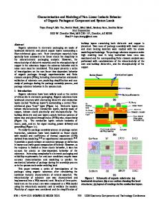
The physics starts from the relative displacement between two parts and leads to the acoustic pressure radiated. A global solving scheme is shown in Fig1.
Figure 1: Global solving scheme The model has to be a time domain analytical model. Consequently, each step depicted in the global resolution scheme has to be analytically computed at each time step. Firstly, let us consider the contact between two bodies called the impactor and the impactee. We decided to control the impactor displacement. Thus, we made the assumption that the impactor displacement was always known and was independent of the impact phenomenon. Given that the impactor displacement is known, solving the first step amounts to computing the impactee displacement. According to rattle definition, we can note
3528
Acoustics 08 Paris
3.1
that the relative displacement between the two bodies is normal and that an initial clearance is taken into account. Secondly, the contact has to be located. Consequently, the contact location has to be known before the impact occurs. Therefore, we decided to consider a point contact. Then, geometries at the impact location and materials are necessary to compute the impact force. The impactee vibratory response is computed solving the motion equations. The impactee geometry and boundary conditions have to allow an analytical solving. Finally, to simplify the acoustic pressure computation, we consider that only the impactee radiates in the audible frequency domain.
2.2
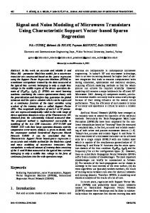
The impacted baffled plate was supported on its four edges. The baffle was put on a concrete acoustic enclosure containing the impact system. The impactor was a half sphere fixed on the shaker exit as shown in Fig3. Thus, the displacement of the impactor was controlled for each experiment. The sphere and plate materials came from automotive subsystems known to generate annoying rattle noises.
Presentation of the model
The analytical model describes a random repeated impact between a sphere and a baffled plate simply supported on its four edges. As shown in Fig2, a sphere of radius R impacts a plate of dimensions Lx × Ly × h at a point M . The sphere is controlled by a randomly generated displacement (for instance, a white noise) along z axis. A clearance j is initially taken into account. The acoustic pressure is computed at a point P . Note that, to fit with modeling choices exposed above, dimensions of the sphere must be small enough not to radiate in the audible frequency domain.
Figure 3: Test bench
3.2
Experimental set up
Three kinds of measurement were carried out. For each plate, an experimental modal analysis was performed with an impact hammer. Thus, for each configuration, we measured Φmn and ωmn which respectively correspond to the plate mode shape and the natural frequencie of each mode mn. Normal velocity of the vibrating surface was measured with a sweeping laser vibrometer. The acquisition was performed on the opposite side of the impacted face of the plate. The plate was meshed to define measurement points. For each measurement point, 30 acquisitions were done and averaged. At the end of the measurement, output data were available with respect to frequency. The analysis frequency band was between 0 and 4 kHz. The last measurement was an acoustic acquisition. The test-bench was covered by an acoustic enclosure with a microphone inside measuring the acoustic pressure radiated from the impacted plate. Output data were available in time domain and the sampling frequency was 51.2 kHz. During both last exposed kinds of measurement, an accelerometer and a load transducer were placed just under the impactor to get the impactor acceleration and the impact force. Depending on the kind of measurements, output data were in time or frequency domain.
Figure 2: Analytical model Experimental bench has to be as close as possible to the analytical model.
3
Description of the test-bench
Experimental Approach
The test-bench had to generate rattle noises using simple geometries. The first aim of this experimental approach was to validate the analytical model with experimental data. Consequently, the experimental apparatus had to allow the measurement of the key parameters identified in the modeling approach presentation. An analysis of experimental data was carried out to highlight some interesting results to characterize rattle noises.
3.3
Experimental procedure
The experiment that generated rattle noises presented three points that brought modeling difficulties. Firstly, the excitation was a repeated random impact. Secondly, experimental boundary conditions were speci-
3529
Acoustics 08 Paris fic. Finally, the materials were little known polymeric materials. For each point exposed above, some reference experiments were performed to validate the modeling. For the first point, some experiments were performed using a simply supported steel plate. Both vibratory and acoustic measurements were carried out successively for a direct excitation (Sinus and white noise), a repetitive impact (The impactor is controlled by a sinusoidal displacement) and a randomly repeated impact (The impactor is controlled by a white noise displacement). For the second point, the reference experiment was an impacted aluminum plate with specific boundary conditions. It is important to note that, experimentally, the plate was just put on its edges to prevent the plate from falling down and to create an initial clearance with the impactor. Foam end stop avoided motions along x and y axis. Both vibratory and acoustic measurements were performed for different kinds of repeated impacts. Different polymeric plates were used to validate the last point. For those experiments, the impactor displacement was generated by a low frequency white noise and a recorded road profile. Note that, only acoustic measurements were done for the road excitation whereas both acoustic and vibratory acquisitions were carried out for white noise excitation.
(a)
(b)
4 4.1
Analysis of experimental data
Figure 4: Time evolution of the acceleration of the impactor 4(a)- the impact force 4(b)
Impact phenomena
Vibratory and acoustic responses of a directly excited plate are well known. Therefore, we decided to present results for impacted plates. Concerning the original physical phenomena, observations are similar for both the simply supported steel plate and the aluminum plate with specific boundary conditions. Consequently, we just present the results arising from an impacted aluminum plate by a polymeric sphere controlled by a sinusoidal displacement. Fig4 reports the variation of the impactor displacement and the impact force. For both figures, time axes are the same. We can clearly identify impact phenomena. The impact can be characterized as a sudden deceleration of the impactor and, at the same time, as a contact force impulse. It can be noted that, both in the acceleration and force variation graphs, the magnitude is not constant. An assumption to explain this observation is that the initial position of the plate is not the same at the beginning of each impact. Finally, it can be noted that the force impulse magnitude seems to be dependent on the deceleration impulse magnitude. The measured acoustic pressure variation also presents impulses as shown in the lower graph of Fig5. With regard to force variation, it can be noticed that magnitudes are interdependent and that there is a delay between the maximum of both force and acoustic pressure impulses. It can be checked that the delay corresponds to the time for the acoustic wave to propagate from the impact point to the acoustic recording point. Finally, it can be observed that the acoustic pressure impulse is followed by a decaying oscillation which can be called
the ringing noise. The upper graph of Fig5 is a representation of the same acoustic pressure variation with respect to time and frequency. We can note that impacts appear as a broad band signal.
4.2
Specific boundary conditions
The experimental modal analysis shows that the specific boundary conditions are similar to typical results for a free plate.
4.3
Polymeric plates
Observations are nearly the same for experiments using polymeric plates. However, to get an order of magnitude, we summarize the key parameters maxima in Table 1. The impactor was controlled by a broad band white noise (0 − 20kHz). All data in the table, are absolute maximum values. wimp , vimp and γimp are respectively the maxima of position, velocity and acceleration of the impactor.
4.4
Rattle noises
Here, we are looking for a way to compare different rattle noises. It is important to keep in mind that rattle noises are non-stationary signals. Consequently, a comparison in time domain is not reliable. Moreover, a representation in frequency domain is not relevant because it is strongly dependent on the part of the signal picked. Furthermore, acoustic pressure impulses are not as clean as
3530
Acoustics 08 Paris
Figure 5: Evolution of the acoustic pressure radiated in time and frequency domain (up) and in time domain (down)
Fimp en N wimp en m vimp en m/s γimp en m/s2 Pac en P a
Polymer 1 3, 94 12, 71.10−5 5, 91.10−2 227 0, 82
Polymer 2 4, 57 8, 26.10−5 3, 63.10−2 690 0, 65
Figure 6: Evolution of the acoustic pressure of rattle noise coming from a polymeric plate in time and frequency domain (up) and in time domain (down)
Polymer 3 4, 36 9, 22.10−5 4, 12.10−2 670 0, 49
5.2
To use more relevant sounds, rattle noises were mixed with an automotive background noise. Disparity tests were carried out to describe the influence of the sound mixing. The test results are presented in Fig7. Therefore we conclude that, independently of the sound mixing, rattle sounds are qualitatively judged equal. Note that, coherently, mixed rattle noises are less annoying than not mixed. In future work, we will not need to mix modeled rattle noises to perform sensitivity investigation on key parameters.
Table 1: Order of magnitude of key parameters of impacted polymeric plates
those observed with an impacted metal plate as it can be observed in the lower graph of Fig6 which represents acoustic pressure variation for a rattle noise. The upper graph represents the same acoustic pressure with respect to time and frequency. As previously observed, the impact is characterized by a broad band signal. Therefore, we can locate the exact impact time using that representation. Although we can locate impacts, the comparison of different rattle noises still remains confusing. A psychoacoustic approach has to be done to find a metric for rattle noises.
5
Psychoacoustic approach
About 60 rattle noises were generated using the testbench, 12 were used in different perceptive tests detailed in [13].
5.1
Influence of automotive background noise
Figure 7: Influence of sound mixing
Frequency band of rattle noise
5.3
According to automotive literature, the rattle noises typical frequency bandwidth is (0 − 8kHz). Disparity tests were performed to check the useful frequency band comparing a raw sound to the same sound filtered at different frequencies. Results of these tests show the importance of considering all the audible frequency band to study rattle noises.
Metric
Perceptive tests were done to quantify the rattle noises induced annoyance. Results were validated carrying out disparity tests. To identify the metric, we first computed all classical perceptive parameters using a commercial software. Then, we performed a linear regression to correlate the annoyance with perceptive parameters. The
3531
Acoustics 08 Paris research department of Renault is gratefully acknowledged. This study has been carried out thanks to the help of all the team of LVA (Laboratory of Vibration and Acoustics) of INSA in Lyon.
metric that best correlates with the annoyance is a linear combination of the loudness and the intelligibility, Eq (1). Annoyance = a×Loudness+b×Intelligibility+c (1)
References
a, b and c are constant data (note that a and b are negative). The loudness is computed according to the ISO 532-B standard. The intelligibility is computed according to the ANSI S3.5 standard. The metric is validated for rattle noises generated on the test-bench and mixed with an automotive background noise as shown in Fig8. The mean relative error is about 6%. In the future, this annoyance metric will be applied on computed rattle noises.
[1] A. Akay. A review of impact noise. Journal of American Society of Acoustics, 64(4):977–987, 1978. [2] V. Acary and B. Brogliato. Coefficients de restitution et efforts aux impacts. Revue et comparaison des estimations analytiques. INRIA - Institution National de Recherche en Informatique et en Automatique, 2004. [3] C. Rajalingham and S. Rakheja. Analysis of impact force variation during collision of two bodies using a single-degree-of-freedom system model. Journal of Sound and Vibration, 229(4):823–835, 2000. [4] W. Goldsmith. Impact. 1960. [5] D. J. Wagg, G. Karpodinis, and S. R. Bishop. An experimental study of the impulse response of a vibro-impacting cantilever beam. Journal of Sound and Vibration, 228(2):243–264, 1999. [6] E. J. Richards, M. E. Westcoot, and R. K. Jeyapalan. On the prediction of impact noise, i: Acceleration noise. Journal of Sound and Vibration, 62(4):547–575, 1979.
Figure 8: Comparison between measured and computed annoyance
6
[7] A. Akay and T. H. Hogdson. Sound radiation from an accelerated or decelerated sphere. Journal of American Society of Acoustics, 63(2):313–318, 1978.
Conclusion
This paper presented rattle noises modeling choices to identify key parameters and, consequently, to justify the associated test-bench conception. An experimental procedure was proposed to gradually validate the modeling and to understand physical phenomena behind rattle noises. An analysis of experimental results was conducted to highlight the original physical phenomenon and to get key parameters orders of magnitude. This study shows the difficulties encountered to find a relevant representation of rattle noises. Nevertheless, we demonstrated that impacts can be located in an acoustic pressure signal using a representation with respect to time and frequency. Perceptive tests provided interesting results on the rattle noises useful frequency band and on the influence of the sound mixing with an automotive background noise. A metric was identified to characterize the induced annoyance. In the future, experimental data will be correlated with modeling results. Furthermore, the metric will be useful to perform some sensitivity studies to key parameters.
[8] A. Akay. Acoustic radiation from the elastic impact of a sphere with a slab. Applied Acoustics, 11, 1978. [9] G. Benedetto, R. Spagnolo, and M. Maringelli. Letters to the editor: Transient sound from the impact of a sphere on a thin square plate. Journal of Sound and Vibration, 69(1):157–161, 1980. [10] A. Ross and G. Ostiguy. Propagation of the initial transient noise from an impacted plate. Journal of Sound and Vibration, 301:28–42, 2007. [11] L. A. Wood and K. P. Byrne. Analysis of a random repeated impact process. Journal of Sound and Vibration, 78(3):329–345, 1981. [12] C. H. Lee and K. P. Byrne. Impact statistics for a simple random rattling system. Journal of Sound and Vibration, 119(3):529–543, 1987. [13] A. Coulon, L. Desvard, and N Hamzaoui. R´ealisation et exploitation d’un banc d’essai permettant de caract´eriser les bruits de Rattle d’un habitacle automobile. 2007.
Aknowledgements The authors would like to thank Anne Coulon for her contribution to this studies. All the acoustic team of the
3532