MODELING AND DESIGN METHODOLOGY OF AN EFFICIENT UNDERWATER PROPULSION SYSTEM Pablo Valdivia y Alvarado and Kamal Youcef-Toumi Department of Mechanical Engineering, Massachusetts Institute of Technology Room 3-348, 77 Massachusetts Avenue, Cambridge, MA 02139 USA Email:
[email protected],
[email protected].
ABSTRACT This paper addresses the issues of energy efficiency in mechanisms for underwater locomotion and its accomplishment using a more robust class of mechanical structures. We present a design methodology for fabricating a continuous mechanical fish body such that its kinematic behavior matches parametric models of fish swimming with minimum energy cost. It is concluded that this new design has advantages over classic manipulator type designs. The limitations of this passive design are also discussed and possible solutions proposed.
KEY WORDS Design, energy-efficiency, robustness, underwater vehicles, non-uniform beam forced vibrations.
1. INTRODUCTION One of the main obstacles for increasing the range of action of mobile robots is the problem of energy efficiency. An autonomous robot has to carry its own power supply. However, if it can use energy efficiently while accomplishing its tasks it will be able to run longer missions with the same supply or alternatively, if weight is an issue, use a smaller supply for the same mission. In addition, mechanism robustness is always paramount if missions involve hazardous terrains. However, most autonomous robots use mechanical elements such as electrical motors, gearboxes, linkages, cams, pulleys, etc, to transmit power internally even though these have limited efficiencies. The combination of these elements always yields overall low system efficiencies. Furthermore, the nature of current mechanical elements is not robust enough to withstand harsh environments without sophisticated and complex mechanical protection. As a result most autonomous robots designs are expensive. Scientists have studied fish swimming as an energy efficient alternative to current underwater propulsion methods. Several robots have been built in order to prove
this theory [1,2,3]. However, most of them still use hyperredundant manipulator type designs with classical low efficiency machine elements to transmit power internally. Therefore, the low internal energy transfer might diminish energy gains brought by a more efficient external momentum transfer when using fish swimming modes. Kumph [3] built a tethered 0.82 m long robotic pike with a drive system comprising 5 servomotors. The robot achieved a maximum forward velocity of 0.09 m / s at an actuation frequency of 1 Hz , with a supply of 17 V drawing 0.2 A . The estimated system efficiency was 13.5%. In this paper we address the problem of accomplishing a more efficient mechanical implementation of such swimming modes in a robot. We assume that the kinematic behavior for forward motion described in [1] is a given optimal behavior in terms of achieving efficient momentum transfer to the environment. Then the problem we address is how to design a machine where the implementation of such kinematic behavior (fish swimming modes) is more efficient and requires the least power consumption. Our proposed design has the additional feature of being intrinsically robust and simple. Previous work on alternative mechanisms for achieving fish-like underwater motions is not very extensive. Mcletchie [4] casted flexible fish shapes with a stiffer spine embedded in the models and chose the material modulus so that the wave speed and body amplitude of the actuated fish would match a parametric model of fish swimming. A rod attached to the frontal part of the bodies and driven by an external motor actuated the models by applying a moment. Therefore, models had to be towed. The vibrational response of the models was found numerically, thus there was a lack of an analytical solution to which a designer could relate for further analysis and development. Maximum overall system efficiency was estimated to be close to 30% at an actuation frequency of 6.5 Hz , and an actuation angle of 7 o . The net thrust at this efficiency was close to 0.2 N . Davidson and Julian [5] built a radio controlled maneuverable fish with a flexible actuated tail. However,
no publications were found with details of their design methodology and performance measurements. Blickhan et al. [6] did studies on the benefits of elastic energy storage in steady swimming. Based on dolphin swimming data they calculated optimal spring compliances. The values found were similar to measured tendon compliances. Harper et al. [7] investigated the potential benefit of elastic energy storage in the propulsion of a swimming robot. They concluded that the addition of linear springs to the system provides a means to reduce energy required of the power supply. The current work presents the design methodology for a potentially more efficient class of underwater propulsion mechanisms using body compliance and natural modes of vibration to eliminate internal transmission mechanisms in order to achieve the desired kinematics. We illustrate the processes of design and fabrication. Finally we present experimental performance measurements of the resulting robot fish.
2. DESIGN METHODOLOGY We want to design a robot that swims in the manner of a fish. Two important fish swimming modes that are well understood by the current art are named anguilliform and carangiform. The former is an oscillatory mode in which the entire body participates but amplitude increases towards the rear end of the body. The latter mode is such that oscillations become significant only in the posterior half or even third part of the fish length, the front of the fish almost does not move. Studies point to the idea that carangiform swimming mode is more efficient and can achieve higher speeds [8]. Therefore, we chose to design a robot that uses the carangiform swimming mode. Our design methodology consisted of fabricating a robot with a rigid anterior part and a flexible posterior part, which from now on we will refer to as tail. The tail was modeled as a non-uniform flexible beam and the forced vibrations response was derived and used to design a tail whose dominant modes of vibration corresponded closely to a kinematic model of body deformation in a fish. According to [1], one such model of body deformation is a traveling wave that increases in amplitude from the nose to the tail of a fish and is given by:
(
yb (xb , t ) = c1 xb + c2 xb
2
)[sin(K x )cos(ω t ) + cos(K x )sin(ω t )] (1) b
b
where yb is the lateral displacement of the fish body at a distance xb from the fish nose. We will assume that the values of the linear wave amplitude envelope c1 , the quadratic wave amplitude envelope c2 , the body wave number K , and the body wave frequency ω are known
for a given fish (or application). Our thesis is that the actuation of a mechanism whose principal modes of vibration correspond to the desired motions in (1) has the potential of requiring less energy than actuating a manipulator type design such as in [1,3] where motions of each link are controlled to achieve the desired kinematics. We argue that required “trajectories” can be achieved using only one actuator instead of a discrete number in the case of a manipulator type design. Furthermore, internal transmission elements are eliminated. In the next section we develop a dynamic model of the tail that will be used for the design.
3. TAIL MODEL Rigid
y
Flexible
( )
x
y x, t
lr Figure 1: Schematic of robot body with associated reference frame for modeling.
Figure 1 shows a diagram of the basic configuration of the robot together with the reference frame used for the development of the model. Since our design exploits the carangiform swimming mode, the posterior third of the body is stiff whereas the anterior two thirds of the body are flexible, lr denotes the length of the rigid part of the robot body ( x = xb − lr ). The manner in which we achieve this will be further explained in section 4. The robot’s tail can be modeled as a Bernoulli-Euler beam with varying cross-sectional area. We consider this model appropriate since for most fish the tail amplitude of motion is not very big compared with their length (the excursion of the tip of the tail is approximately 0.14 of the overall body length) [9]. Therefore, all the mass elements in the flexible tail can be assumed to move in pure translations. In addition, most of the potential energy is due to bending rather than shear. l
y 2r
M
(t )
( )
x
y x, t a Figure 2: Tail model
Figure 2 shows the tail modeled as a beam with variable cross-section. Parameters l , and a , denote the length of the tail and the distance from the tail base at which a timevarying actuation moment M acts. The forced vibrations of a non-uniform beam moving steadily in a fluid are described by the following partial differential equation
ρA(x )
∂2 y ∂2 ⎡ ∂2 y ⎤ + 2 ⎢ EI (x ) 2 ⎥ = f (x, t ) − γ (w) , 2 ∂t ∂x ⎣ ∂x ⎦
where y is the lateral displacement of a tail element relative to a reference frame fixed to the tail as displayed in figure 2. The density ρ and the modulus of elasticity E of the tail are taken to be constant throughout the tail continuum. The cross-sectional area A and the second moment of cross-sectional area I of the tail vary with x . A distributed force f is used to generalize the possible actuation forces. The resistive forces γ (w) due to interaction with the fluid environment depend on the normal component w of relative velocity between the tail and the fluid environment. For an undulating body with body wave speed V and mean swimming speed U relative to the stream, w is given by ∂y ⎛ U ⎞ ∂y w= . ⎜1 − ⎟ = ε ∂t ⎝ V ⎠ ∂t The resistive forces dependence on w can be approximated to be linear at very low Reynolds numbers and is generally taken to be quadratic at high Reynolds numbers. We are interested in the case of swimming at high Reynolds numbers thus we should model the resistive forces as some sort of form drag. However, the resulting PDE would be nonlinear and finding a closed form solution becomes more difficult. Thus, we approximate the resistive forces by a linear dependence (viscous drag). This underestimation of the resistive forces will tend to yield results that are overestimations of the actual behavior, but it would allow us to find a closed form solution for the predicted transverse motions of the tail. Therefore, if we assume that the flow around the fish is steady (ε = cst.) , we can model the resistive forces by a term analogous to viscous damping, with a damping coefficient that varies with x since the area of the tail changes with x as well: ∂y ∂2 y ∂2 ⎡ ∂2 y ⎤ ρA(x ) 2 + 2 ⎢ EI (x ) 2 ⎥ = f (x, t ) − C (x ) . (2) ∂t ∂t ∂x ⎣ ∂x ⎦
The transformation leading from (2) to (4) is explained in [10,11]. It involves essentially a change of variable u = ψ y , where the functions ψ are polynomials in x of at least second order. In our analysis we assumed a quadratic variation of the tail cross section since this assumption is not terribly unrepresentative of real fish profiles. Thus, we use: ⎛ ⎝
x⎞ l⎠
Where A0 , I 0 , and C0 are the cross sectional area, the second moment of cross-sectional area, and the damping coefficient respectively at x = 0 . Equation (4) can be solved using the method of virtual work. The transverse deflection response, as expressed with the change of variable, is expanded in series u=
⎛ ∂ y⎞ ⎜⎜ EI (x ) 2 ⎟⎟ = 0 ∂x ⎠ x =l ⎝ 2
∂ ⎛ ∂ y⎞ ⎜⎜ EI (x ) 2 ⎟⎟ = 0. ∂x ⎝ ∂x ⎠ x =l 2
j
(6)
j
We define a virtual displacement for the ith mode to be δui = δφi X i . The sum of all virtual works in the system should add up to zero as explained in [12]. The response of the ith vibrational mode can be found by using the Duhamel integral [12]. Reverting the change of variables we find the response to be − c0
∞
y ( x, t ) = ∑ i =1
X i X ia′ e 2 ρA ψρ A0 pi
t
0
c0
τ
2 ρA ∫ e M a (τ )sin pi (t − τ )dτ . t
0
(7 )
0
In our actuation scheme, the moment M a applied at a distance a from the tail base is chosen as M a (t ) = M sin (Ω t ) (8) Combining equations (7) and (8) , and evaluating the integral we get the following expression y ( x, t ) =
∑ f (x )e [g (t ) + e h (t )] ∞
− Nt
Nt
i
i
(9)
i
i =1
f i (x ) = g i (t ) =
(3)
Finding a closed form solution for the problem defined by equations (2) and (3) is not straightforward. However, closed form solutions exist for the uniform counterpart of the PDE given by ∂ 2u ∂ 4u ∂u ρA0 2 + EI 0 4 = f (x, t ) − C0 (4) ∂t ∂x ∂t
∞
∑φ (t )X (x ) j =1
where, The boundary conditions for this case (clamped-free) are, ⎛ ∂y ⎞ ( y )x=0 = 0 ⎜ ⎟ =0 ⎝ ∂x ⎠ x =0
2
ψ = ⎜1 − α ⎟ , A = A0ψ , I = I 0ψ 2 , C = C0ψ . (5)
hi (t ) =
X i X ia′ M , ψρ A0 pi
N=
C0 2 ρA0
( ) + 2(N
)
2 Npi Ω cos( pi t ) + Ω N 2 − pi + Ω 2 sin ( pi t )
(N
2
+ pi
2 2
2
2
(
)
− pi Ω + Ω 4 2
2
)
− 2 Npi Ω cos(Ω t ) + pi N + pi − Ω 2 sin (Ω t )
(N
2
+ pi
) + 2(N
2 2
2
2
2
)
− pi Ω + Ω 4 2
2
The steady state response is then y ss (x, t ) =
∞
∑ f (x ) h (t ) i
i
(10)
i =1
For our boundary conditions (clamped-free), the normalized eigenfunctions and angular frequencies are given by
X i = ai [cos(k i x ) − cosh (k i x )] + bi [sin (k i x ) − sinh (k i x )] pi = k i
2
EI 0 ρA0
where the ratio of coefficients ai and bi is known, and ⎛ 1⎞π ki ≈ ⎜ i − ⎟ , [12]. Now for design purposes we would ⎝ 2⎠ l like to match the terms in equations (1) and (10) , so we rewrite equation (10) as ∞ X X′ y ss (x, t ) = ∑ i ia [Qi cos(Ωt ) + Ri sin (Ωt )] ψ i =1 where, −2 N ΩM Qi = 2 2 2 2 ρ A0 N + pi + 2 N 2 − pi Ω 2 + Ω 4
((
Ri =
((
(N
ρ A0 N + pi 2
)
2
(
)
+ pi − Ω M 2
2
) + 2(N
2 2
2
)
)
)
)
− pi Ω 2 + Ω 4 2
Therefore, for the transverse vibrations of the tail to match the parametric model of equation (1) , the following conditions must be met (for x ≥ 0 ) ∞ X X′ 2 ∑ i ia Qi = c1 xb + c2 xb sin (K xb ) i =1 ∞
∑ i =1
ψ
X i X ia′
ψ
( (
) )
Ri = c1 xb + c2 xb cos(K xb ) 2
(11)
Ω=ω
The speed of convergence of the series in equations (11) depends on the values of the parameters. Depending on the dimensions and the complexity of the parametric model that needs to be matched, more or less terms (modes) might be needed for an approximation to match the desired kinematics.
4. ROBOT DESIGN AND FABRICATION 4.1 DESIGN The previous section described the dynamics of motion of a general continuum whose shape resembles a fish tail. The tail’s modes of vibration can be made to match the parametric model of fish swimming presented in equation (1) by using the constraints given by equations (11) in the design of the continuum. The third equation in (11) is the only explicit condition since it prescribes the actuation frequency Ω to the body wave frequency ω of the fish being modeled. The series on the left hand side of the first two equations in (11) depend on nine design parameters: a , A0 , I 0 , α , l , E , ρ , M , Ω . If we want to preserve the geometry of the fish we are
modeling, the parameters A0 , I 0 , α , and l are known. Then the remaining unknown design parameters are the actuation point a , the modulus of elasticity E , the density ρ , and the magnitude of actuation moment M (since Ω is prescribed by the third equation in (11) ).
From the first two equations in (11) we can get the following condition ∞
∑ X X′Q i
ia
i
i =1 ∞
∑ X i X ia′ Ri
= tan (K xb )
(12)
i =1
We can see from equation (12) that for an acceptable approximation, for this particular parametric model of swimming, at least the first two terms of the series must be considered since otherwise the left hand side of the equation would be a constant. Also, the right hand side of the equation has discontinuities at xb = n π 2 K (with n = 1,3,5,... ). The problem is reduced then to finding a set of parameters to match the models in the two sides of equation (12) , achieving the smallest error possible. This fitting can be done numerically in a least squares sense. We included the constraint of minimizing the value for M . The designer can prescribe some of the unknown variables if he chooses to do so. Also by including the constraint of minimizing the value of the magnitude of the actuation moment M we are effectively minimizing the energy consumption of the design that matches the kinematic behavior of a fish, since the input power is Pin = MΩ . The parameters chosen for our design are listed in table 1. Our design is radio controlled for testing purposes so the actuation frequency can be set to any value during operation. However, the results presented in section 5 indicate that an optimal performance is achieved using a frequency close to the value prescribed. Parameter a A0
I0
α l E
ρ
M
Value 0.05 [m]
3.04 × 10 −3 [m 2 ] 4.9 × 10 −7 [m 4 ] 0.42 0.1 [m] 0.04 [MPa]
1080 [Kg m 3 ] 1.4 [Nm]
Table 1: Design Parameters
4.2 FABRICATION An appropriate material can be chosen once we know the required material properties. The next step is to fabricate a tail that corresponds to the required geometry. In addition
it is convenient to have rigid parts embedded in the continuum, which give a good support for actuation. We use simple casting techniques and shape deposition manufacturing (SDM) principles, which are explained in [13]. For most of the parts we use a machinable base, such as a block of solid wax, where the mold of a given part’s profile can be machined. Next, parts such as actuators, or sensors, are positioned inside the empty mold and the required material is poured in resin form. Once the material cures, some machining can still be done to complete what becomes a single continuous piece. Figure 3 shows the tail design. Flexible and stiff sections are stacked together forming a single continuum. Stiff sections are used for actuation support, and flexible sections provide a compliant structure that transmits momentum to the environment. The harmonically varying moment input is applied by actuating the stiff plate embedded inside the tail at a distance a from the tail base. A servomotor actuates the plate by pulling two inextensible cables attached to the plate. It should be noted that while we are still using a classical actuator, in this case a servomotor, no classical transmission elements (pulleys, gear boxes, etc.) are present between the servomotor and the end-effector, in this case the tail. Also since the design is monolithic no sealing is required for that section of the body.
Figure 4: Tail fabrication and testing. Clockwise from top left: Rigid tail components stacked in mold, Components bound by polymer, Top view of tail reaching maximum deflection, Top view of tail and servo assembly. Receiver
Batteries
Figure 5: Complete fish.
Flexible Polymer
5. EXPERIMENTAL SETUP & RESULTS
Cables
Stiff Polymer Servomotor
In order to measure propulsion performance parameters such as trust and speed, several experiments were performed. The experiments where made in a towing tank where models can be towed at controlled velocities by a carriage and also swim freely. The tank is 30 m long, 2.5 m wide, and 1.2 m deep. The carriage is suspended over the testing tank and driven by a flat belt. Output from sensors can be recorded by the tank data acquisition system. The sampling frequency used was 200 Hz .
Figure 3: Continuous fish tail design
The main advantages of this type of design are that the compliance is implemented by the structure itself, and the mechanism is self-contained. The goal is to eventually use a more efficient type of actuator. Figure 4 shows the procedure for the tail fabrication and the actuation of the finished tail. The tail is casted using a two-part mold. The rigid parts, made from IE-70D polyurethane, are sandwiched inside the mold, and IE-10AH polyurethane (both from Innovative Polymers, Inc., St. Johns, MI) is poured in between them. The maximum tail bit amplitude is close to 0.1 m in air, with an input torque of 1.4 Nm . Figure 5 displays the entire robot body and the location of some of its components.
Flexure transmission
Load cell Attachment plate
Figure 6: Test setup and experimental fixture details.
Figure 6 displays a photograph of the mechanical fish attached to the carriage mast and a solid model diagram displaying the important features of the setup. A flexural mechanism was designed to hold the fish underwater while transmitting the forces acting onto it to a tension compression load cell without applying any shear to it.
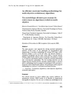
Experiments were made to measure both the thrusts and velocities achievable with our design. Figure 7 shows measured static thrusts and average forward velocities as a function of the actuation frequency. A maximum is noted in both graphs at an operational frequency close to 4 Hz . This most likely reflects a combined effect of reaching the optimum point of the servomotor efficiency and being close to the prescribed frequency by which the fish swimming mode is more closely mimicked.
not decrease the overall energy efficiency, which would defeat the purpose of the design.
7. ACKNOWLEDGEMENTS The authors greatly appreciate the support of the Singapore-MIT Alliance program. The authors would also like to acknowledge Schlumberger Ltd. for the financial support and the personnel of the MIT ocean engineering towing tank for allowing us to use their facilities for experimentation.
REFERENCES
Figure 7: Thrust and average velocities versus actuation frequency.
6. DISCUSSION AND CONCLUSIONS Measurements of the actual tail mechanism energy efficiency are still in progress. Once these are finished we will be able to draw a more conclusive comparison between our design and classical manipulator designs in terms of mechanical efficiency. Meanwhile, we have presented a dynamic model for the forced vibrations of a damped non-uniform beam, representing the tail of a robotic fish, and applied it to the design of an alternative underwater propulsion mechanism. The resulting design was built and tested showing good performance behavior compared to the present art. A maximum thrust close to 0.4 N was achieved at an operating frequency of 4 Hz . Also the peak average forward velocity of 0.095 m / s was reached at a similar frequency. The present design eliminates the need for classical internal transmission elements between the actuator and the end-effector, which in this case is the whole tail. Furthermore, the fact that the mechanism is a single monolithic part eliminates the need for sealing in that section, and also makes is more robust against failure. Finally, one of the main limitations of this mechanism is that it is passive in nature. It is designed to perform under certain specific environment conditions assumed in the model. Therefore, as it is, the design cannot react against disturbances. Hence, future work should address the incorporation of some active mechanisms inside the tail continuum. Nevertheless, any mechanism added should
[1] D.S. Barrett, Propulsive efficiency of a flexible hull underwater vehicle. PhD thesis, Massachusetts Institute of Technology, 1996. [2] J.M. Anderson, Vorticity control for efficient propulsion. PhD thesis, Massachusetts Institute of Technology, 1996. [3] J.M. Kumph, The design of a free swimming robot pike. B.S. thesis, Massachusetts Institute of Technology, 1996. [4] K.M. Mcletchie, Drag reduction of an elastic fish model. B.S. thesis, Massachusetts Institute of Technology, 2002. [5] N. Davidson, N. Julian, www/me.berkeley.edu/hel/ calibot.htm [6] R. Blickhan, J.-Y. Cheng. Energy storage by elastic mechanisms in the tail of large swimmers – a reevaluation. Journal of Theoretical Biology, 168:1994, 315-321. [7] K.A. Harper, M.D. Berkemeier, S. Grace, Decreasing the energy costs of swimming robots through passive elastic elements, Proc. IEEE Int. Conf. On Robotics and Automation, Albuquerque, NM, 1997, 1839-1844. [8] J. Lighthill, Mathematical Biofluiddynamics (Philadelfia, PA: Society for Industrial and Applied Mathematics, 1975). [9] J.J. Videler, Fish swimming (London: Chapman & Hall, 1993). [10] H.P.W. Gottlieb, Comments on Vibrations of Nonuniform Beams and Rods, Journal of Sound and Vibration 195, 1996, 139-140. [11] S. Abrate, Vibration of Non-Uniform Rods and Beams, Journal Sound and Vibration, 185(4), 1995, 703716. [12] S. Timoshenko, D.H. Young, W. Weaver Jr, Vibration problems in engineering (John Wiley & Sons, 1974). [13] J. G. Cham, B.L. Pruitt, M.R. Cutkosky, M. Binnard, L.E. Weiss, G. Neplotnik, Layered manufacturingwith embedded components: Process planning issues, Proc. Of ASME Design Engineering Technical Conference, Las Vegas, NV, 1999.