International Journal of Modeling and Optimization, Vol. 2, No. 5, October 2012
Modeling and Simulating of Omni Directional Soccer Robot Omid Bakhshandeh Babarsad and Maziar Ahmad Sharbafi
robots' central blobs which are in blue or yellow colors (see Fig.1). A server computer has to receive vision data and after processing data the soccer game engine generates the velocity of robots in their coordinates system. Small size robot can move in all directions, accelerate up to 3 (m/s) and is capable of kicking the ball about 10 (m/s) with its magnetic kicker. Also a chip kick mechanism is devised for shooting ball in air. There exist many contributions in simulating and modeling soccer robots in the literature [1]-[3] previous works on simulating soccer robots mainly worked with linear velocity on robot's body without concentrating on the exact mechanism of robot motion [1]. In such ways robotics experts are not capable of working on low level control of robots. The major problem with simulating robot motion is designing omni-directional wheels for robots in simulators. Modeling such wheels in their actual scales and quantities causes a time consuming process in physics engines. For instance a simulation with 10 four wheeled robot that each wheel contains 20 small wheels -for omni directional motionneeds 800 tiny wheels. Fig. 2 shows the structure of these wheels.
Abstract—Modeling and simulation in robotics research has always been one of the most beneficial ways of evaluating structural and behavioral designs before implementation in real world. Robot soccer is a research domain started from 1998 as a practical league of RoboCup international competitions. Simulating omni-directional wheels of such robots has recently been a controversial issue among developers. In this paper an innovative simulator including all the features of small size soccer robots in a 5 on 5 game, is introduced. In addition, a novel technique in modeling omni directional wheels is applied with considering just two parameters of wheels: longitude and lateral. The advantages of this simulation environment are shown via investigation of its feasible computation time and accuracy in robots' performance estimation. Index Terms—Omni-directional wheel, robocup, soccer robot, wheel simulation.
I. INTRODUCTION Generating a simulation environment is an inevitable approach for testing and developing proposed algorithms to be verified to implement in reality. This is highly applicable robotic projects like small size soccer robot as one of Robocup competitions league. Different branches of researches from mechanical and electrical designs to image processing, control and decision making in a dynamic time critical environment converted such competitive matches to a challenging scientific robotic test bed. Evaluation of strategies based on artificial intelligence in multi agent environment besides the control and practical constraints make complex problem with different aspects. Thus, a comprehensive simulator with characteristics, near reality as much as possible, is a significant requirement. In these matches each team participates with 5 robots fitted in a cylinder with 9 (cm) radius and 15 (cm) height. The robots play soccer with an orange golf ball on a green carpeted field with length and width equal to 6.05 (m) and 4.05 (m) respectively. All objects on the field are tracked by a standard vision system (SSL-Vision) that processes the data provided by two cameras installed on a camera bar located 4 (m) above the playground with 60 frame-per-second frequency. SSL-Vision software will send positions and the orientations of ten robots and the ball location via UDP multicast. Teams are separated from each other with the
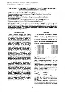
Fig. 1. Small size robots simulator view
Whole of the works in this paper are performed in Mechatronics Research Laboratory (MRL) participating in Robocup competitions from 2008. In the following, at first a summarized description of MRL robot structure, communication with vision system and simulator engine is presented. Next, the simulator structure is explained with focus on the novel method for simulating omni-directional wheel shaped robot. Figure 1 shows a snapshot of this 3d simulator. Whole required mechanisms to have a complete simulator from motion, contacts and are considered in this section. Finally, the results compared with robot operation are displayed to show the admirable performance of this
Manuscript received July 15, 2012; revised August 20, 2012. O. Bakhshandeh is with the Electrical and Computer Engineering Department, Qazvin branch, Islamic Azad University, Qazvin, Iran. (e-mail:
[email protected]). M. A. Sharbafi was with Mechatronics Electrical and Computer Engineering Department, Qazvin branch, Islamic Azad University, Qazvin, Iran. (e-mail:
[email protected]).
629
International Journal of Modeling and Optimization, Vol. 2, No. 5, October 2012
simulator.
Fig. 2. Real omnidirectional wheel
II. MRL SOCCER ROBOT AND SIMULATOR ENGINE
Fig. 4. Hierarchical playing architecture
In this section different parts of the structure that should be simulated from robot specification to vision and communications and errors are described. As mentioned above, MRL soccer robot is a mobile robot with 18 (cm) diameter and height of 15 (cm) as shown in figure 3. It has 4 omni-directional wheels with 4 brushless motor which can generate 96 (mNm) torque for each wheel. Robot has an IR transmitter and receiver, placed in front of its body to detect the possession of the ball. It could not be executable with vision data because of its latency and inaccurate ball positioning respect to the robot. Wireless system’s role is transferring data including the desired linear and angular velocities of the robot, chip or direct kicking power and dribbler's motor speed commands. Wireless systems usually have common problems like delayed or damaged data. Furthermore, data packets may be received improper or even completely dismissed.
The target of explaining different sections of our playing constructions is to introduce various parts that should be simulated to have a complete model. Delay in wireless and vision, noise and imprecise data are considered in our simulator besides different aspects of robot mechanical structure characteristics. Figures 3 and 5 display the real and simulated robot respectively. This is the base of the simulation which is described more in the next section.
III. THE SIMULATED ROBOT MODEL The detail of the simulating MRL soccer robot which is introduced in the previous section is the subject of this section. In other words, all of the mentioned particles of robots should be assembled in the simulator including noises, delays and uncertainties either. First the general scheme of the simulator is presented and because of the importance of modeling the omni directional wheel, it will be described the second part of this section. A. Robot Structure Simulation For simulating our robot comprehensively, the whole rigid bodies are developed by NVIDIA PhysX which is a powerful hardware accelerated physic engine. By applying PhysX any rigid body collisions and complex body shapes definitions are attainable desirably. Robot’s mechanical design (as shown in Fig. 3) can be seen fully developed and modeled in CAD software which is used for simulating all parts (see Figure 5). It is started with considering a minimum bounding shape to model the robot. This object is designed as a convex mesh physics shape. Wheels and other dedicated parts are attached to this body as their main entities. In the real physical robot the center of mass (COM) is in the height of 2(cm) from robot’s chassis which is achievable in PhysX too.
Fig. 3. MRL small size soccer robot
Dribbler mechanisms role is to spin the ball as fast as it can to hold the ball in front of the robot. Dribbler speed and texture have a significant role in generating the required force. Ball handling is a desired feature which is achievable better with inserting damping mechanism in the dribbler structure. Our AI systems duty is to process robots conditions and determine the team formation and strategy including each robot motion, and every other required actions. The motion is produced by sending required velocities of the wheels. In [4] we described our roles and skills details and relations between them which are inspired from CMU team game structure [5], [6]. Fig. 4 shows our hierarchical playing architecture.
Fig. 5. CAD model of soccer robot
630
International Journal of Modeling and Optimization, Vol. 2, No. 5, October 2012
Our magnetic kicking mechanism is designed by shooting the ball with an initial velocity after a contact. In direct kick the only parameter is the initial velocity and direction of the ball which has a unique relation with force vector. The nonlinear relation between the initial velocity of ball after kicking (V(k)) and the received value of kick power (k) from wireless is identified by fitting a polynomial to the extracted values for different kicks as depicted in equation (1). Figure 6 illustrates the relation between kick power and velocity and its acceptable estimation. 𝑉 𝑘 = −0.0001𝑘 3 + 0.0213𝑘 2 − 0.0315𝑘 − 0.0098 (1) Fig. 6. Kick powers and velocity relations, solid line is the real data and the dotted is the estimation with 3D polynomial
Of course in chip kick, this is not so simple and the angle of this vector with XY-plane (the field) is important too. An accurate relation between the command sent to the robot and its effect in chip kick is identified by neural network. Two layer MLP with 12 and 2 neurons in each layer is sufficient to give a satisfying estimation. The only remained part of kick mechanism is the ball detection sensor. IR sensors are simulated by computing the ball contact with the line, placed in front of the robot from sender position to the receiver. This is done by utilization of contact reporter which is built in the mentioned engine. As mentioned before our real wireless system has common problems like latency and data lost. Sometimes data packets aren’t properly received by robots. A probabilistic model for data transfer has been introduced to simulate a real wireless system. Measuring lost data compared with the size of sent packets shows a detectable relation with distance between the robot and the wireless transmitter (d). A Gaussian distribution is fitted to the wireless noise with the mean (m) and variance (𝜎) related to the distance (see (2) and (3)). 2
𝑚 = (1 + arctan 0.4(𝑑 − 5) ) 𝜋
𝑑
𝜎 = 0.03log (1 + ) 5
B. Omni dicrectional wheel simulation The difference between the omni directional wheel and regular wheel is in their motions in lateral direction. These wheels which are named omni wheels too, are able to move in two directions perpendicular to each other. To manufacture these wheels in real world a number of tiny wheels added to the main wheel to create another degree of freedom. Fig. 2 shows the complete wheel with 18 side wheels on main frame to move easily in lateral direction. Simulating wheels like its real causes heavy process in simulation engine. Our main novelty is simulating this wheel with a new method that is very simple in implementation, very low in process cost and perfect in performance. A wheel shape in simulation has a tire force function that gets slip as an input parameter that is different for lateral and longitudinal direction. The output of function is a value of grip. In spring model of tire function, the frictional constraints are modeled as griped in both longitudinal and lateral dimensions. Grip level as output of tire force function can be interpreted as a normalized spring coefficient. By scaling the output with the normal impulse and the stiffness parameter the actual spring coefficient can be computed. Equation (4) Shows the relation of grip level in which Fmax is the maximum friction force in each direction, S is the stiffness and 𝐹𝑒𝑥𝑡 is the extremum force which is described more in the following.
(2) (3)
After all processes in simulator the data has to send back to AI. This data can be send as a world model that considers all objects information like robot real positions and orientation. Simulator is middleware here that simulates robot movement and also vision system. So recursion from simulator to AI system has to pass from vision system without vision problem. But in the simulator uncertainties, noisy data, delay and interference are added. Some of such exogenous or internal factors of vision are Image buffering delay in cameras and Image digitalization in computer. In this model there is not corruption because of reliability of network data transmission. A delay between 6 to 24 milliseconds has been added in random way to simulate the loop completely. Finally a roller which rotates with different speeds according to the commanded value received from wireless is attached at the top of the kicker to simulate the dribbler. The roller friction is tunable to produce different adhesiveness for different used materials. With all the above considerations, the mobile robots are simulated very accurately and near realistic manner. All noises and delays are calculated to generate very similar behavior to the real world. Every computational cost is considered and using different tests shows this similarity in practice.
𝐹𝑚𝑎𝑥 = 𝐹𝑒𝑥𝑡 × 𝑆
(4)
The force function can be described with 4 parameters as inputs. Two first parameters are extremum slip and extremum value which represent maximum slippage factor and maximum value determining function peak point. Another two parameters represent asymptotes of slip and force value (like figure8). Tire force function is computed in longitude and lateral directions with different values. It helps us to change the maximum slip per force in lateral direction more than its default value. Fig.7 shows that how tire forces function works and table 1 shows Omni wheel parameters. TABLE I. Stiffness Longitude direction Lateral direction
631
PARAMETERS OF WHEEL INTWO DIMENTIONS Extremum Extremum Asymptotes Asymptote value slip value slip
106
2
0.0001
0.01
0.0002
106
0.002
1
0.001
2
International Journal of Modeling and Optimization, Vol. 2, No. 5, October 2012
For extracting parameters of tire force function in longitude direction an inverse solution analysis is selected. In this method robot moved with a constant linear force in linear direction and wheel angular speed (𝜔𝑖 ) extracted from shaft encoder. The linear velocities of wheels affecting (𝑣) the robot are calculated from equation (5) as an inverse kinematic equation between robot linear velocity and robot wheel speed. Therefore, the slip (S) which needs linear and angular wheel velocity (𝑣 and 𝜔) determined by inverse kinematic and shaft encoder measurement is, computed by (6). In this equation 𝑅is the radius of the wheel. 𝜔1 −𝐶𝑜𝑠(𝜃) −𝑆𝑖𝑛 𝜃 𝑅 𝜔2 𝑆𝑖𝑛(𝜃) −𝐶𝑜𝑠(𝜃) 𝑅 𝑉𝑥 𝑉𝑦 𝜔3 = 𝐶𝑜𝑠(𝜃) 𝑆𝑖𝑛(𝜃) 𝑅 𝜔 𝜔4 −𝑆𝑖𝑛(𝜃) 𝐶𝑜𝑠(𝜃) 𝑅 𝑠𝑙𝑖𝑝 =
1− −1 +
𝑅𝜔 𝑣 𝑣 𝑅𝜔
, 𝑣 > 𝑅𝜔 > 0 , 𝑅𝜔 > 𝑣 > 0
IV. EXPERIMENTAL AND CONTROL RESULTS Real robots after manufacturing have problems like dissimilarities in symmetric objects (like wheels), low efficiency in power transmission, uncertainties in mechanical or electrical structures and etc that cause some problems in low level control. These problems can affect high level controls and finally robot may not move different maneuvers desirably. Some of such problems are intrinsically robot dependent and should be solved by control approaches. However, simulating robot with all of its properties give the opportunity of testing and implementing new methods that their evaluation in real world have a huge amount of cost. A simulator for small size soccer robot is developed in this paper with the mentioned omni-directional wheel model. To investigate the simulator performance different test was applied which could not be explained completely for the shortage of the space. Thus some tests are described in the following as prominent samples. In this test the robot should move on a rectangle as shown in figure 9. The control commands sent to the real robot and the simulator are the same with similar frequencies. The obtained results from simulation are comparable favorably with real robot’s movements and navigations. It is the basic necessary step in simulating the robot virtually. Further combinational verification tests are performed too. For example, a pass-shoot strategy is designed for two robots requiring accurate timing and control designs. In this test after obtaining satisfying performance in simulation by an emotional learning method named BELBIC, the robots could make cooperation in real world too. For more information about BELBIC and its application in soccer robots see [7] to [9]. Using this simulation environment various artificial intelligence based decision making mechanisms are evaluated and improved before implementing on real robots.
(5)
(6)
Fig. 7. Forces in two directions: Red arrow shows the lateral force and Blue arrow shows th longtitude force.
In other hand, to calculate the force on the wheels, firstly the motor torque (𝜏) is derived by (7). In this formula 𝑢, 𝑅, 𝑘 and 𝑘′ are the input voltage, the motor coil resistance, the motor torque constant and the motor speed constant respectively. After determining the wheel forces and slip in different conditions the required diagram is obtained which is show in figure 8. With this approach the parameters of Table 1 are extracted that makes an exact model for the wheels in longitude direction. 𝜏=
𝑘 𝑅
.𝑢 −
𝑘 𝑅.𝑘 ′
.
V. CONCLUSION AND FUTURE WORKS In this paper a virtual platform to evaluate control, decision making and strategy designing for small size robot playing soccer is presented. Noticeable achievements to reach the third team in RoboCup international competitions 2010 in Singapore is a sample of the improvements resulted from applying this tools. Many learning algorithms and multi agent decision making approaches are investigated in this environment till now.
(7)
Finally the lateral manner of the wheels is extracted first by generating different maneuvers for robots and gathering the required data. Next, investigating different parameters to produce such behaviors in simulator resulted in values pointed in Table 1 for lateral direction. In other words, we tried to reach the best coefficients to attain similar operation in robot motion as a result of relation between lateral slip and force.
Fig. 9. Exprimental results of robot movement in simulator and real world
One problem in strategy evaluation in small size soccer competitions is the shortage of friendly matches against opponent team. Playing a real team against a virtual team in
Fig. 8. Diagram of force against slip which is calculated in practice.
632
International Journal of Modeling and Optimization, Vol. 2, No. 5, October 2012
simulator is our next target to promote our team performance. Some initial steps to reach this target are passed and it will be attained in near future that will result in considerable improvement in our team operation. This mixed situation between reality and simulation is a precious attainable goal in such research environment.
[9]
Omid Bakhshandeh Babarsad was born in Esfahan, Iran, 1989. He is currently undergraduate student at Electrical and Computer Engineering department of Qazvin Islamic Azad University, majoring in Software Engineering. He started his research in Mechatroncis Research Laboratory of Iran from2008 as research assistant in the field of Robotics and Multi-agent Systems. He also served as the head of Artificial Intelligence group of Small-Size soccer team. His research interests include Robotics& Artificial Intelligence, Motion Planning, and Robot Dynamic Control.
REFERENCES [1]
[2]
[3]
[4]
[5]
[6]
[7]
[8]
International Journal of Intelligent Automation and Soft Computing, vol. 10, no.1, 2004, pp. 11-22. M. A. Sharbafi and C. Lucas, “Designing a Football Team of Robots from Beginning to End,” International Journal of Intelligent Technology (IJIT), vol. 3, no. 2, 2006, pp.101-108.
C. Chuengsatiansup, T. Charoensripongsa, K. Wongsuphasawat, K. Rattana, P. Doungsodsri, A. Buathong, K. Wejwittayaklung, M. Wongsaisuwan, and W. Wannasuphoprasit., “Extended Team Description Paper,” in Proc. 13th International RoboCup Symposium, Graz, Austria, 2009. S. Zickler, Physics-Based Robot Motion Planning in Dynamic Multi-Body Environments, Ph.D. thesis, Dept. Computer Science, Carnegie Mellon Univ, CMU-CS-10-115, 2010. B. Browning and E. Tryzelaar, “UberSim: A Realistic Simulation Engine for Robot Soccer,” in Proc. Autonomous Agents and Multi-Agent Systems, AAMAS'03, Australia, 2003. M. A. Sharbafi, M. Hoshyari, S. Esmaeelpourfard, O. Bakhshandeh, M. Haajseyedjavadi, and D. Esmaeeli, “MRL 2010 Team Description,” in Proc. 14th International RoboCup Symposium, Singapore, 2010. B. Browning, J. R. Bruce, M. Bowling, and M. Veloso, “STP: Skills tactics and plansfor multi-robot control in adversarial environments,” International Journal of System and Control Engineering, 2005. S. Zickler, J. Biswas, J. R. Bruce, Michael Licitra, and M. Veloso, “CMDragons 2010 Extended Team Description,” in Proc. 14th International RoboCup Symposium, Singapore, 2010. M. A. Sharbafi, C. Lucas, and R. Daneshvar, “Motion control of omni-directional three-wheel robots by brain-emotional-learning-based intelligent controller,” IEEE Trans on Systems, Man, and Cybernetics, Part C: Applications and Reviews, vol. 40, 2010, pp. 630-638. C. Lucas, D. Shahmirzadi, and N. Sheikholeslami, “Introducing BELBIC: Brain Emotional Learning Based Intelligent Controller,”
Maziar A. Sharbafi was born in Rasht 1981. He received his B.S. degree in Electrical/Control Engineering from Sharif University of Technology, and the M.Sc. in the same field from University of Tehran, both in Tehran, Iran in 2003 and 2006, respectively. He is currently working towards the Ph.D. degree in electrical engineering, systems, and control in the School of Engineering, Department of Electrical Engineering and Computer Science, the University of Tehran, Tehran, Iran. He served as a Researcher and Faculty Member in Islamic Azad University of Qazvin since 2005. From August 2011 till now, he was an Intern at Lauflabor group in TU Darmstadt, Darmstadt, Germany. His research interests include theory and practice of control in robotics and, generally, the application of dynamical systems and nonlinear control.
633