Enzyme-Catalysed Substrate Conversion in a Microbioreactor ... impact of the diffusion modulus and the Biot number as well as porosity on ...... limit of one.
International Journal on Advances in Systems and Measurements, vol 11 no 1 & 2, year 2018, http://www.iariajournals.org/systems_and_measurements/
173
Modeling and Simulation of Enzyme-Catalysed Substrate Conversion in a Microbioreactor Linas Petkeviˇcius and Romas Baronas Institute of Computer Science, Vilnius University, Didlaukio st. 47, Vilnius, Lithuania Email: {linas.petkevicius, romas.baronas}@mif.vu.lt
Abstract—Mathematical modeling and numerical simulation of non-linear mathematical model for digital simulation of an enzyme loaded porous microreactor is investigated in this paper. The model is based on a system of reaction-diffusion equations, containing a non-linear term related to the Michaelis-Menten kinetics, and involves three regions: the enzyme microreactor where the enzyme reaction as well as mass transport by diffusion take place, a diffusion limiting region (the Nernst layer), where only the mass transport by diffusion takes place, and a convective region, where the constant analyte concentration is maintained. The digital simulation was carried out using the finite difference technique. Assuming well-stirred conditions, impact of the diffusion modulus and the Biot number as well as porosity on transient effectiveness factor and yield factor has been numerically investigated. The simulation results showed that the Nernst layer must be taken into consideration when modelling micro-size bioreactors. The computational simulations showed that the yield factor and the effectiveness factors have different properties to describe system productivity. Keywords—reaction-diffusion; Michaelis - Menten kinetics; microbioreactor; porosity; CSTR.
or other materials within the reactor; (3) reusability; and (4) control over reactions that are allowed, shell can be formated to avoid the diffusion of all material to microreactor. Rapid progress was noticed in integrating microfluidic reactors and biocatalytic reactions [13]. The combination of miniaturized technologies and microfluidics allows to increase the efficiency of bioprocess. In the recent review, Jansen concludes that endto-end fabrication and on-demand manufacturing based on microreactors have growing industrial interest, which leads to development and progress [14]. However, coupling microreactors and biocatalysis is highly complex, requiring an integrated approach addressing biocatalyst features, reaction kinetics, mass transfer and microreactors geometry [13][15].
substrate
I. I NTRODUCTION This paper is an extension of the work originally reported in The Ninth International Conference on Advances in System Simulation [1]. Continuous-flow stirred tank reactors (CSTR) are common in chemical industries [2][3]. Although a stirred tank is a usual construction of industrial enzyme reactors, the effectiveness and optimal construction of CSTR remain open to study [4][5]. Specifically, further research is needed due to the application of the immobilized enzymes, such as biocatalysts, on a manufactoring scale that requires to use the reactors of different types, including CSTR [6][7][8]. The CSTR often refers to the model used to estimate the operation parameters when using a continuous agitatedtank reactor to reach a specified output [7]. In the last few decades, immobilized enzyme reactor models have evolved significantly with a wide range of applications in food industry [9], waste cleaning [10], immobilization of microbial cells [11][12]. The main advantages of immobilized cells over nonimmobilized cells can be enumerated: (1) incapsulation not only keep enzyme from wash out, but also protect it during the changes of various conditions, such as pH, temperature, and toxic compounds; (2) cells do not stick up to bioreactors
Ωc
Unit cell
product
Ωm Ωd
Figure 1. Continuous stirred tank reactor with enzyme-loaded microreactors (pellets) and a zoomed unit cell to be modelled.
2018, © Copyright by authors, Published under agreement with IARIA - www.iaria.org
International Journal on Advances in Systems and Measurements, vol 11 no 1 & 2, year 2018, http://www.iariajournals.org/systems_and_measurements/
174 Mathematical models have been widely used to investigate the kinetic peculiarities of the enzyme microreactors [8][13]. Models coupling the enzyme-catalysed reaction with the diffusion in enzyme microreactors are usually used. Since containing catalytic particles, the analyte in CSTR is well-stirred and set in powerful motion, the mass transport by diffusion outside the microreactors is usually neglected [15][16]. Mixing within CSTR creates the Nernst layer while increasing stirrer speed can reduce the thickness of Nernst layer. However, due to the inner force of attraction, the zero thickness of the diffusion shell (layer) can not be achieved [17]. We consider an array of identical spherical microreactors placed in the CSTR shown in Figure 1 [7], where area Ωm denotes a microreactor, Ωd denotes surrounding diffusion shell and Ωc is a convective region. The goal of this work was to investigate the dependencies of the internal and external diffusion limitations on the yield and the effectiveness factors, modelled by reaction-diffusion equations, containing a non-linear term related to MichaelisMenten kinetics [7][8][18]. The model involves three regions: the enzyme microreactor, where the enzyme reaction, as well as the mass transport by diffusion take place, a diffusion limiting region, where only the mass transport by diffusion takes place, and a convective region, where the constant analyte concentration is maintained. In practice, the laboratory experiments aimed to be performed with as small as possible particle layer size to avoid process limitations caused by diffusion of the reacting solution in the catalyst pore system. There is a practice of performing experiments under the fluiddynamic conditions in order to eliminate the lack of mass transfer liminations outside the particles. However, it is not always possible to reduce the particle size as much as it is required for avoiding diffusion limitations. It has been shown that for first order chemical reactions, the transient effectiveness factor depends not only on the Thiele modulus but also on the adsorption capacity of the system, the fact that should be taken into account when kinetic experiments are designed. However, the type of immobilization can raise the diffusion difference within the reactor and the Nernst layer. The porous materials as well as nanoparticles immobilized in mircoreactors, can be considered porous with respect to the Nernst layer. This paper also analyses how the porosity impacts effectiveness factor as well as the yield factor. Due to a strong non-linearity of the reaction term, the computer simulation was carried out using the finite difference technique [19]. The rest of the paper is organised as follows: in Section II, the mathematical model and microbioreactor characteristics are described; Section III formulates a dimensionless model and determines the main parameters of the bioreactor; Section IV describes the numerical model and the simulator; in Section V, the results of numerical experiments are presented, and conclusions close the article.
Product
Microreactor
r
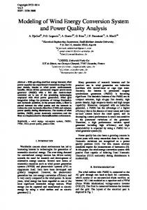
Nernst Substrate Figure 2. Principal structure of the unit cell consisting of a microbioreactor and the Nernst diffusion shell in homogenously distributed volume.
II. M ATHEMATICAL MODEL We consider an array of identical spherical microreactors placed in a continuous ideally stirred-tank reactor [7]. Assuming a uniform distribution of the microreactors (see Figure 2) in the tank and a comparably great distance between adjacent microreactors and fact that microreactor volume Vm is significantly smaller than the tank volume V , the spherical unit cell was modelled by an enzyme-loaded microreactor (pellet) and a surrounding diffusion shell (the Nernst diffusion layer). The principal structure of the tank containing uniformly distributed microreactors and a unit cell are presented in Figure 1, where Ωm denotes a microreactor (MR), Ωd stands for the diffusion shell and Ωc is a convective region. In the enzyme-loaded MR layer we consider the enzymecatalyzed reaction kf kcat GGGGGGB E + SF GG ESGGGGGGGGAE + P, kr
(1)
the substrate (S) combines reversibly with an enzyme (E) to form a complex (ES). The complex then dissociates into the product (P) and the enzyme is regenerated [20][21]. The kf , kr and kcat are forward rate, reverse rate and catalytic rate constanst, respectively. Assuming the steady-state approximation, the concentration of the intermediate complex (ES) does not change and may be neglected when modelling the biochemical behaviour of the microreactor [7][21][22]. In the resulting scheme, the substrate (S) is enzymatically converted to the product (P), E
S −→ P.
2018, © Copyright by authors, Published under agreement with IARIA - www.iaria.org
(2)
International Journal on Advances in Systems and Measurements, vol 11 no 1 & 2, year 2018, http://www.iariajournals.org/systems_and_measurements/
175 A. Governing Equations Considering the symmetrical geometry of the microreactor and homogenised distribution of the immobilized enzyme inside the porous microreactor, the mathematical model can be described in one-dimensional domain using the radial distance [7]. Coupling enzymatic reaction in the microreactor (region Ωm ) with the one-dimensional-in-space diffusion, described by Fick’s second law, and considering the steady-state of a system (2) leads to the following governing equations of the reaction-diffusion type (0 < r < R0 ): Vmax Sm 1 d � 2 dSm � r = , r2 dr dr KM + Sm Vmax Sm 1 d � 2 dPm � r = − , DP,m 2 r dr dr KM + Sm DS,m
(3a) (3b)
r stands for space variable, Sm = Sm (r) and Pm = Pm (r) are the concentrations of the substrate and the reaction product in the microreactor, respectively, R0 is the radius of the microreactor, Vmax = kcat E0 is the maximal enzymatic rate and KM = (kr + kcat )/kf is the Michaelis constant. The volumetric reaction as a function from concentration is marked as V (S) = Vmax Sm /(KM + Sm ). In the Nernst diffusion layer Ωd only the mass transport by diffusion takes place (R0 < r < R1 ): 1 d � 2 dSd � DS,d 2 r = 0, (4a) r dr dr � � 1 d 2 dPd DP,d 2 r = 0, (4b) r dr dr Sd = Sd (r) and Pd = Pd (r) are the concentrations of the substrate and the reaction product in the diffusion shell. Respectively, DS,d and DP,d are the diffusion coefficients of the materials in the bulk solution and R1 is the radius of the unit cell. Microbioreactors are microparticles immobilized with the enzyme, so the core of the particle is porous. Due to the porosity of microbioreactor diffusion coefficients DS,m and DP,m can be expressed through diffusion coefficients for bulk solution [23], DS,d �t DS,m = (5a) τ DP,d �t DP,m = , (5b) τ �t is porosity (void fraction space in a material) and τ is tortuosity. B. Boundary Conditions Fluxes of the substrate and the product through the stagnant external diffusion shell is assumed to be equal to the corresponding fluxes entering the surface of the microreactor, �t dSm dSd = , (6a) τ dr r=R0 dr r=R0 �t dPm dPd = . (6b) τ dr r=R0 dr r=R0
The formal partition coefficient φ is used to describe the specificity of concentration distribution of the compounds between two neighboring regions [7][24], Sm (R0 )
= φSd (R0 ),
(7a)
Pm (R0 )
= φPd (R0 ).
(7b)
The partition within the reactor caused by porosity, so we assume that the porosity and partition coefficient is in a linear relationship: φ = �t
(8)
Due to the symmetry of the microreactor, the zero-flux boundary conditions are defined for the center of the microreactor (r = 0), DS,d �t dSm = 0, (9a) τ dr r=0 DP,d �t dPm = 0. (9b) τ dr r=0 According to the Nernst approach, the shell of thickness ν = R1 −R0 remains unchanged with time [17][19]. Away from it, the solution is in motion and is uniform in concentration. Due to the continuous injection of the substrate into the stirred tank and washing off the product, the concentration in the convective region remains unchanged: Sd (R1 )
=
S0 ,
(10a)
Pd (R1 )
=
0.
(10b)
The thickness ν of the Nernst diffusion shell depends on the nature and stirring up of the buffer solution. Usually, more intensive stirring corresponds to the thinner diffusion layer (shell). C. Microbioreactor characteristics In many industrial processes, especially in the production of low-value added products like biopesticides, bio-fertilizers, bio-surfactants ect. [10], it is important to continuously improve the yield and/or productivity of the reactor system [8]. The productivity is important, since this ensures an efficient utilization of the production capacity, i.e., the bioreactors. The yield of the desired product on the substrate is one of the most important criteria for design and optimization of bioreactors. The economic feasibility of the process is expressed by the yield factor as the ratio of product formation rate and the substrate uptake rate [7][8]. The bioreactor construction is efficient enough when the product emission is relatively large with given substrate ¯P,O can be calamount used. The product emission rate E culated by an integration of the product flux over the outer surface of the diffusion shell [8],
2018, © Copyright by authors, Published under agreement with IARIA - www.iaria.org
International Journal on Advances in Systems and Measurements, vol 11 no 1 & 2, year 2018, http://www.iariajournals.org/systems_and_measurements/
176 ¯P,O E
Z
= =
π
Z
2π
dPd R2 sin(θ)dϕdθ dr r=R1 1 0 0 dPd . (11) −4πR12 DP,d dr r=R1 −
DP,d
The product emission rate has the units of mol/s. The substrate consumption rate C¯S over the whole microreactor can be calculated as follows: Z R0 Z 2π Z π ¯ V (S) sin(θ)dθdϕr2 dr CS = 0 0 0 Z R0 Z 2π 2V (S)dϕr2 dr = 0 0 Z R0 = 4π V (S)r2 dr. 0 Z R0 Vmax Sm (r) 2 = 4π r dr. (12) K M + Sm (r) 0 The substrate emission rate also have the units of mol/s. The yield factor γ for the microreactor system, as well as for the entire tank reactor shown in Figure 1, can be defined by the ratio of the product emission rate to the substrate consumption rate, ¯P,O E (13) γ= ¯ . CS The yield factor is characterised by an actual rate within the reactor in contrast to the actual product formation rate. The effectiveness factors characterise the interaction between action in microbioreactor in porous catalytic pellets and microreactors when particles are solid [25], and often used in the biochemical engineering [26][27]. The effectiveness factors are usually defined in terms of the stationary mode of biocatalytic systems [25][27][28]. The effectiveness factor η can be calculated [29]: � C¯S /V (S0 ) (4πR03 /3) RR 3 0 0 V (S)r2 dr R03 V (S0 ) R R0 Vmax Sm (r) 2 3 0 KM +Sm (r) r dr
� η
= = =
R03
Vmax S0 KM +S0
.
(14)
Summarising definition (14), the effectiveness factor η can be defined also as the ratio of the average reaction rate actually observed in the MR to ideal rate evaluated at the bulk concentrations of the substrate [29][30]. III. D IMENSIONLESS MODEL In order to define the main governing parameters of the two compartment model (3)-(10), the dimensional variable r
and unknown concentrations Sm (r), Pm (r), Sd (r), Pd (r) are replaced with the following dimensionless parameters: Sm r , Sem = re = R0 KM (15) Pm e Sd Pd Pem = , Sd = , Ped = , KM KM KM re is the dimensionless distance from the microreactor center and Sem (e r), Pem (e r), Sed (e r), Ped (e r) are the dimensionless concentrations. Having defined dimensionless variables and unknowns, the following dimensionless parameters characterize the domain geometry and the substrate concentration in the bulk: S0 τ ν , Se0 = , D= (16) νe = R0 KM �t νe is the dimensionless thickness of the Nernst diffusion layer, Se0 is the dimensionless substrate concentration in the bulk solution, D is the dimensionless diffusion coefficient. The dimensionless thickness of the microreactor equals one. A. Model description The governing equations (3) in the dimensionless coordinates are expressed as follows (0 < re < 1): e 1 d � 2 dSem � 2 Sm = 0, (17a) r e − σ re2 de r de r 1 + Sem 1 d � 2 dPem � Sem re + σ2 = 0, (17b) 2 re de r de r 1 + Sem σ is the Thiele modulus or the Damk¨ohler number [8][31][32] defined as: Vmax R02 Vmax R02 τ σ2 = = . (18) KM DS,m KM DS,d �t The governing equations (4) take the following form (1 < re < 1 + νe): 1 d � 2 dSed � D 2 re = 0, (19a) re de r de r 1 d � 2 dPed � D 2 re = 0. (19b) re de r de r The matching conditions (6)-(10) become: dSed dSem = D de r re=1 de r re=1 dPem dPed = D , de r re=1 de r re=1
Sem (1) = Pem (1) = dSem de r re=0 dPem de r re=0
(20a) (20b)
φSed (1), φPed (1),
(21b)
=
0,
(22a)
=
0,
(22b)
2018, © Copyright by authors, Published under agreement with IARIA - www.iaria.org
(21a)
International Journal on Advances in Systems and Measurements, vol 11 no 1 & 2, year 2018, http://www.iariajournals.org/systems_and_measurements/
177
Sed (1 + νe) Ped (1 + νe)
= Se0 ,
(23a)
=
(23b)
0.
B. Model reduction The second order homogeneous differential equations (19) can be easily integrated (1 < re < 1 + νe) [19], d1 c1 + c2 , Ped (e r) = + d2 , (24) Sed (e r) = re re c1 , c2 , d1 and d2 are constants of integration. By evaluating the integration constants from the boundary conditions (20) and (23), we get the following solution to the system (19): � � e 1 dSm �t 1 e e (25a) − Sd (e r) = S0 − , τ re 1 + νe de r r=1 � � e �t 1 1 dPm Ped (e r) = − − (25b) . τ re 1 + νe de r r=1 After applying the obtained expressions (25), the matching conditions (21) can be expressed as the flux boundary conditions, ! em (1) dSem S = βS Se0 − , (26a) de r re=1 φ ! dPem Pem (1) = βP − , (26b) de r re=1 φ βS and βP are the Biot numbers for the substrate and the product [33][34], respectively. βS βP
=
DS,d DS,d �t τ
1 + νe = νe
DS,d R1 DS,d �t (R1 − τ
=
DP,d 1 + νe = DP,d �t νe
DP,d R1
β
D. Limiting cases Analytical solutions of product and substrate concentrations can be found for the limiting cases when volumetric reactions become zero or first kinetics [7][33]. Analytical solutions have practical value, the models when diffusion is not fixed and depends on porosity and tortuosity are rarely analyzed (see equation (5)). Zero order kinetics: When the substrate concentration S0 is very high compared to the Michaelis constant KM (S0 � KM ), the reaction term reduces to the zero order reaction rate Vmax , then volumetric reactions becomes V (S) ≈ Vmax . The solution of substrate and product concentrations with the boundary conditions (6)-(10) gives the following expressions: Sm (r)
=
Pm (r)
=
R0 )
DP,d �t (R1 τ
− R0 ) τ 1 + νe R1 = βS = βP = =D . �t νe (R1 − R0 ) τ
enzyme kinetics controls the bioreactor action. The action is under diffusion control when σ 2 � 1. The Biot number indicates the internal mass transfer resistance to the external one [33][34]. When the Biot number is small, the effect of the external diffusion is the most marked. As the Biot number increases, the effect of the external diffusion becomes less important. The diffusion module and the Biot number are widely used in analysis and design of different bioreactors [34]. The experiment conducted by Kont et al. [11] proved the external mass-transfer limitations to be negligible for the Biot number greater than one using the first order kinetics model of CSTR and packed-bed reactors (PBR), which corresponds condition (10). Typically, designers seek for bioreactors acting in the reaction-limited regime, since in this case reaction and diffusion occur on different time scales [35].
(27)
The boundary value problem (17)-(23) has been reduced to the boundary value problem described by the governing equations (17), the boundary condition (22) and the flux boundary condition (26). C. Governing parameters The initial set of model parameters has been reduced to the following aggregate dimensionless parameters: νe is the relative thickness of the Nernst diffusion layer, σ is the diffusion module, β is the Biot number, Se0 is the substrate concentration in the bulk, φ is the formal partition coefficient. The dimensionless factor σ 2 essentially compares the rate of enzyme reaction (Vmax /KM ) with the diffusion through the enzyme-loaded microreactor (DS,m /R02 ). If σ 2 � 1, the
� � 2φR02 Vmax τ (28) R02 − r2 + 6DS,d �t β � � Vmax τ 2φR02 R02 − r2 + (29) 6DP,d �t β
φS0 −
Sd (r)
=
Pd (r)
=
� � 1 Vmax R03 1 − S0 − 3DS,d r R1 � � 3 Vmax R0 1 1 − 3DP,d r R1
(30) (31)
Corollary 1. The yield and effectiveness factors are equal to one for zero order kinetics.
¯0 E P,O
dPd dr r=R1 (−1) 3 Vmax −4πR12 DP,d R0 3 DP,d R12 4 3 πR Vmax 3 0 4 3 πR Vmax . 3 0 ¯0 E P,O =1 C¯ 0
= −4πR12 DP,d = =
C¯S0
=
γ0
=
S
2018, © Copyright by authors, Published under agreement with IARIA - www.iaria.org
(32)
International Journal on Advances in Systems and Measurements, vol 11 no 1 & 2, year 2018, http://www.iariajournals.org/systems_and_measurements/
178 0.3
0.2
P(r) 0.1 0.05
β
0 1.0 1.2 1.4
1.6
1
2
r
-1
-2
e0 = 1 porosity �t = 0.75 and Figure 3. Concentration profiles of the product concentration in the microreactor (simulated at the substrate concentration S different values of the Biot number β ∈ [1, 1.6], the other parameters are as defined in (40)).
1 0.75
S( r )
0.5 0.25 0 0.1 1
σ 10 100
1
2
r
-1
-2
e0 = 1, porosity �t = 1 and Figure 4. Concentration profiles of the substrate concentration in the microreactor (simulated at the substrate concentration S different values of the Thiele module σ ∈ [10−1 , 102 ], the other parameters are as defined in (40)).
R R0
Vmax r2 dr =1 (33) R03 Vmax The zero order kinetics rate does not depend on the concentration profiles, so, naturally, such type of system is efficient. First order kinetics: At such low concentration of the substrate as S0 � KM , the non-linear reaction rate in η
0
=
3
0
Sm (r)
=
Sd (r)
=
Pm (r)
=
Pd (r)
=
equations (3) reduces to the first order reaction rate, then volumetric reactions becomes V (S) ≈ Vmax S/KM . The solution of substrate and product concentrations with the boundary conditions (6)-(10) at first order kinetics gives the following expressions:
φ S0 R1 R0 τ /� sinh (mr) , r (τ /� R1 sinh (σ) + φ (R1 − R0 ) (σ cosh (σ) − sinh (σ))) S0 R1 (τ /� r sinh (σ) + φ (r − R0 ) (σ cosh (σ) − sinh (σ))) r (τ /� R1 sinh (σ) + φ (R1 − R0 ) (σ cosh (σ) − sinh (σ))) �0 ≤ r ≤ R0 .
− φ S0 (R1 φ σ cosh(σ)r − R0 φ σ cosh(σ)r − sinh(mr)R0 R1 D∗ τ /� �� −R1 φ sinh(σ)r + R1 sinh(σ)D∗ τ /� r + R0 φ sinh(σ)r) � � m2 r(τ /� R1 sinh(σ) + φ (R1 − R0 )(σ cosh(σ) − sinh(σ)))D∗ , −
φ S0 R0 (R1 − r) (σ cosh (σ) − sinh (σ)) ∗ 1 sinh (σ) + φ (R1 − R0 ) (σ cosh (σ) − sinh (σ))) D R0 ≤ r ≤ R1 .
m2 r (τ /� R
2018, © Copyright by authors, Published under agreement with IARIA - www.iaria.org
(34) (35)
(36) (37)
International Journal on Advances in Systems and Measurements, vol 11 no 1 & 2, year 2018, http://www.iariajournals.org/systems_and_measurements/
179 Corollary 2. The yield and effectiveness factors have the following form at first order kinetics.
(39)
diffusion layer fast, allow the concentrations approach the straight line because of linearity of governing equations in the area re ∈ (1, 1 + νe). On the other hand, high Thiele modulus values (σ ≥ 100) (see Figure 3) lead to significant differences in concentration distribution across the outer boundary of the microreactor. Both the radius of dimensionless microreactor and the Nerst layer thickness is equal to one.
One can see that the effectiveness coefficient lies in the interval [0, 1], while yield can grow. However, in practical applications σ � 1.
B. The impact of the Biot number, Thiele module and substrate concentration
γ1 η1
= σ2 , =
3βφ(σ coth σ − 1) . 2 σ (β + φ(σ coth σ − 1))
(38)
IV. D IGITAL SIMULATION OF EXPERIMENTS The non-linearity of the governing equations prevents us from solving the boundary value problem (17)-(23) analytically, hence the numerical model was constructed and solved using finite difference technique [19]. An explicit scheme was used; however, due to Michaelis-Menten non-linearity, further construction of equations was used: n � n Vmax Cm 1 d � 2 dCm r = ± , DC,m · 2 n−1 r dr dr KM + Cm C = S, P . Tridiagonal matrix was constructed from the equations. In the numerical simulation, the scheme was run until the following loss became very small:
To investigate the dependence of the yield factor γ, the effectiveness factor η on the Biot number β, changing the Biot number in a range of [1, 102 ], the factor γ was calculated at different values of the Thiele module σ in a range of [10−1 , 102 ] and the substrate concentration Se0 was calculated in a range of [10−3 , 103 ]. Impact of the Biot number: The results of the calculations of yield factor γ when Biot number β and Thiele module σ is changing and the porosity �t = 0.1, 0.5, 1 are depicted in Figure 5.
L = ||S n − S n−1 ||l2 + ||P n − P n−1 ||l2 < �,
V. R ESULTS AND DISCUSSION
0.8
0.55 0.1
1 1
To investigate the effects of the geometry and catalytic activity of the microreactor, the reactor action was simulated and the yield and the effectiveness factor was calculated for very different values of the Biot number β, the Thiele module σ, the substrate dimensionless concentration S0 , the porosity �t . A. Concentration profiles Figure 3 shows the profiles of the product concentration P calculated from the microreactor model (17)-(23) changing the Biot number β and the porosity equal �t = 0.75. Figure 4 shows the profiles of the substrate concentration S changing the Thiele module σ and the porosity �t = 1. As both figures demonstrate, the following parameters of the model remain unchanged: DS,d = DP,d , β = 1, νe = 1.
1
γ
decay rate value � = 10−14 was used over l2 norm. An explicit scheme of finite difference was built on a uniform discrete grid with 128 points in space direction [18]. The simulator has been programmed by the authors in C++ language [36]. The numerical solution of the mathematical model (17)-(23) was validated by using the exact analytical solutions known for very special cases of the model parameters [7][18][31][34] see equations (28)-(37).
(40)
One can be seen in Figure 4, where low Thiele modulus values σ < 1, which indicates that the species pass the Nernst
σ
10
10
β
100 100
Figure 5. The yield factor γ vs. Biot number β and Thiele module σ at porosity �t : 0.1, 0.5, 1, the other parameters are as in (40).
In Figure 5, the yield factor γ is presented when concentration Se0 is equal to one. It is apparent that maximal efficiency can be achieved only with Thiele module σ < 1. It is worth to mention that porosity can be considered as neglected for yield factor. With large values of Thiele module, the yield factor γ is nearing to zero independently of the porosity �t or β. The yield factor γ, practically, does not depend on β for σ < 1. The Biot number and substrate concentration is neglected to yield factor γ with Thiele module σ < 20. On the other hand, the Nernst diffusion layer may be neglected when the Biot number is higher than approximately 20 [34][37]. Impact of the substrate concentration: Calculation results of the yield factor γ when substrate concentration S0 and Thiele module σ is changing and the porosity �t = 0.1, 0.5, 1 are depicted in Figure 6.
2018, © Copyright by authors, Published under agreement with IARIA - www.iaria.org
International Journal on Advances in Systems and Measurements, vol 11 no 1 & 2, year 2018, http://www.iariajournals.org/systems_and_measurements/
180 validated from calculated factors at zero order (33) and the first order kinetics (39).
γ
1
0.75 1
0.8
0.55 0.1
η
0.5
1000
σ
1
100
10
0.25
10
S
1
0
0.1
0.01
0
100 0.001
1.0 0.8
Figure 6. The yield factor γ vs. Thiele module σ and initial concentration S0 at porosity �t : 0.1, 0.5, 1, the other parameters are as in (40).
C. Impact of the porosity To investigate the dependence of the yield factor γ, the effectiveness factor η on porosity �t , the calculations were performed in a range of [0.1, 1]. The ranges of Thiele module σ, Biot number β and tortuosity was used as in the previous Section. Figure 7 shows the effectiveness factor η as an increasing function of the porosity �t when Thiele module is one and Biot number is two. When the Michaelis-Menten kinetics approaches the first order (Se0 � 1), the effectiveness factor η becomes a linear function from the porosity. The effectiveness factor η approaches one as increased concentrations are becoming zero order kinetics (Se0 � 1). Those limits can be
εt
0.4 0.2
0.01 0.001 0.0
0.1
1
S
1000 100
0
Figure 7. The effectiveness factor η vs. initial concentration S0 and porosity �t , the other parameters are as in (40).
Figure 8 shows the effectiveness factor η as an increasing function of the porosity �t when Thiele module and concentrations are equal to one. The effectiveness factor η, practically, does not depend on the Biot number for β > 2 and increases with increasing the porosity and the Biot number.
1
0.75
η
One can see (Figure 6) a non-linear impact of the substrate concentration on the yield factor. As a function of Se0 , the yield factor γ is a monotonously increasing function with the limit of one. At high values of the Thiele module σ > 20, the yield factor is decreasing to zero near low values of substrate (see Figure 6). The yield factor, limiting value of one, can be reached with the low Thiele module values σ < 20. The yield factor γ is, practically, invariant to changes in the substrate concentration Se0 when the Michaelis-Menten kinetics approach the first order (Se0 � 1) or zero order kinetics (Se0 � 1). In intermediate values of Se0 , when the kinetics changes from the first to zero order, the yield factor γ noticeably increases with increasing the substrate concentration at low Thiele module values. Impact of the Thiele Module: It can be seen in Figure 5 and Figure 6 that the yield factor γ, practically, does not depend on σ and approaches to one when the bioreactor acts notably under the bioreaction control (σ < 20). At mixed conditions when the diffusion action is influenced by both the enzyme kinetics and the diffusion, the yield factor γ noticeably decreases decreasing the substrate concentration S0 . Figure 6 also shows that the factor γ increases while increasing the substrate concentration (as in Figure 6) as well as when increasing the Biot number β (as in Figure 5).
0.6
10
0.5
0.25 0.1 0 1.0
100 0.8 0.6
εt
10
0.4 0.2 0.0
β
1
Figure 8. The effectiveness factor η vs. Biot number β and porosity �t , the other parameters are as in (40).
Figure 9 shows the yield γ as an increasing function of the porosity �t when concentrations are equal to one and the Biot number is two. It is evident that high Thiele module values σ � 10 are significantly descreasing any efficiency of the system and the yield factor practicaly does not depend on the porosity �t . On the other hand, the small Thiele module values give a linear dependency from the porosity. It can be noted that yield as a function of Thiele module is nonlinear and increases with decreasing diffusion module.
2018, © Copyright by authors, Published under agreement with IARIA - www.iaria.org
International Journal on Advances in Systems and Measurements, vol 11 no 1 & 2, year 2018, http://www.iariajournals.org/systems_and_measurements/
181
1
0.5
η
0.75
0.1 0 0.1 1
σ
10 100 0.0
0.2
0.4
0.6
0.8
1.0
εt
Figure 9. The effectiveness factor η vs. the Thiele module σ and porosity �t , the other parameters are as in (40).
Figure 10 shows the yield γ as an increasing function of the Thiele module and practicaly does not depend on the porosity �t when Thiele module is one and the Biot number is two.
only when the enzyme kinetics controls the bioreactor action σ < 20 (Figure 6). The transient effectiveness factor is an increasing function of porosity and, practically, does not depend on the Biot number (Figure 8). However, strong non-linear depencies appear when analysing the impact of porosity and Thiele module (Figure 9). Also, is evident that the effectiveness factor approach zero under diffusion control σ > 10 and is limited of porosity under action control σ < 0.1. The dependency from substrate concentration (Figure 7) also shows a non-linear relationship. The effectiveness increases to one with increase in the substrate concentration and reduces to the linear function of porosity when S0 < 0.01. Such formulation can be useful to find the optimal parameters of such biosystem construction [12]. More importantly, it might improve the design and production of microbioreactors. There are some limitations worth to mention that might be used for the future investigations. First of all, in physical experiments, pellets can not be considered as the perfect spheres, which requires the modelling of more sophisticated domains in 2D and 3D spaces. Secondly, the system with time dependent characteristics should be considered in the future work. R EFERENCES
1
0.8
γ
0.9
0.7
0.1 1
σ
10 100 0.0
0.2
0.4
0.6
0.8
0.55 1.0
εt
Figure 10. The yield factor γ vs. the Thiele module σ and porosity �t , the other parameters are as in (40).
VI. C ONCLUSION AND F UTURE W ORK The mathematical model (3)-(10) and the corresponding dimensionless model (15)-(23) of the microbioreactor can be successfully used to investigate the behaviour of the catalytic microreactor and to optimize its configuration. The yield of the product increases with increasing the substrate concentration (Figure 6) and with decreasing the Thiele module (Figure 5). However, the effectiveness of the yield factor can be achieved to the limit of one, with not high Thiele module value σ < 20. More importantly, the yield factor, practically, does not depend on the Biot number (Figure 5) and the porosity (Figure 10). The increase in the substrate concentration becomes ineffective when the enzyme reaction is under control of reaction control σ < 20 (Figure 6). The high yield can be achieved
[1] L. Petkevicius and R. Baronas, “Numerical Simulation and Analysis of Enzyme-Catalysed Substrate Conversion in a Microbioreactor,” in SIMUL 2017: The Ninth International Conference on Advances in System Simulation. IARIA, 2017, pp. 1–6. [2] A. Regalado-M´endez, R. R. Romero, R. N. Rangel, and S. Skogestad, “Biodiesel Production in Stirred Tank Chemical Reactors: A Numerical Simulation,” in New Trends in Networking, Computing, E-learning, Systems Sciences, and Engineering. Springer, 2015, pp. 109–116. [3] O. N. A˘gda˘g and D. T. Sponza, “Anaerobic/aerobic treatment of municipal landfill leachate in sequential two-stage up-flow anaerobic sludge blanket reactor (UASB)/completely stirred tank reactor (CSTR) systems,” Process Biochemistry, vol. 40, no. 2, pp. 895–902, 2005. [4] A. Miyawaki, S. Taira, and F. Shiraishi, “Performance of continuous stirred-tank reactors connected in series as a photocatalytic reactor system,” Chemical Engineering Journal, vol. 286, pp. 594–601, 2016. [5] M. A. Dareioti and M. Kornaros, “Effect of hydraulic retention time (HRT) on the anaerobic co-digestion of agro-industrial wastes in a twostage CSTR system,” Bioresource Technology, vol. 167, pp. 407–415, 2014. [6] A. J. Straathof and P. Adlercreutz, Applied Biocatalysis. CRC Press, 2000. [7] P. M. Doran, Bioprocess Engineering Principles. Academic Press, 1995. [8] J. Villadsen, J. Nielsen, and G. Liden, Bioreaction Engineering Principles. Dordrecht: Springer, 2011. [9] S. K. Dubey, A. Pandey, and R. S. Sangwan, Current Developments in Biotechnology and Bioengineering: Crop Modification, Nutrition, and Food Production. Elsevier, 2016. [10] J. W. Wong, R. D. Tyagi, and A. Pandey, Current Developments in Biotechnology and Bioengineering: Solid Waste Management. Elsevier, 2016. [11] A. Konti, D. Mamma, D. G. Hatzinikolaou, and D. Kekos, “3-Chloro-1, 2-propanediol biodegradation by Ca-alginate immobilized Pseudomonas putida DSM 437 cells applying different processes: mass transfer effects,” Bioprocess and Biosystems Engineering, vol. 39, no. 10, pp. 1597–1609, 2016. [12] D. Cas¸caval, A. C. Blaga, and A.-I. Galaction, “Diffusional effects on anaerobic biodegradation of pyridine in a stationary basket bioreactor with immobilized Bacillus spp. cells,” Environmental Technology, pp. 1–13, 2017.
2018, © Copyright by authors, Published under agreement with IARIA - www.iaria.org
International Journal on Advances in Systems and Measurements, vol 11 no 1 & 2, year 2018, http://www.iariajournals.org/systems_and_measurements/
182 [13] R. Karande, A. Schmid, and K. Buehler, “Applications of multiphasic microreactors for biocatalytic reactions,” Organic Process Research & Development, vol. 20, no. 2, pp. 361–370, 2016. [14] K. F. Jensen, “Flow chemistry—microreaction technology comes of age,” AIChE Journal, vol. 63, no. 3, pp. 858–869, 2017. [15] F. M. Pereira and S. C. Oliveira, “Occurrence of dead core in catalytic particles containing immobilized enzymes: analysis for the michaelis– menten kinetics and assessment of numerical methods,” Bioprocess and Biosystems Engineering, vol. 39, no. 11, pp. 1717–1727, 2016. [16] M. B. Kerby, R. S. Legge, and A. Tripathi, “Measurements of kinetic parameters in a microfluidic reactor,” Analytical Chemistry, vol. 78, no. 24, pp. 8273–8280, 2006. [17] J. Wang, Analytical Electrochemistry, 3rd ed. Joboken, New Jersey: John Wiley & Sons, 2006. [18] R. Baronas, F. Ivanauskas, and J. Kulys, Mathematical Modeling of Biosensors. Dordrecht: Springer, 2010. [Online]. Available: http://www.springer.com/chemistry/book/978-90-481-3242-3 [19] D. Britz and J. Strutwolf, Digital Simulation in Electrochemistry, 4th ed., ser. Monographs in Electrochemistry. Cham: Springer, 2016. [20] M. F. Chaplin and C. Bucke, “The large-scale use of enzymes in solution,” Enzyme Technology, pp. 138–166, 1990. [21] H. Gutfreund, Kinetics for the Life Sciences. Cambridge: Cambridge University Press, 1995. [22] L. A. Segel and M. Slemrod, “The quasi-steady-state assumption: a case study in perturbation,” SIAM Rev., vol. 31, no. 3, pp. 446–477, 1989. [23] P. Grathwohl, Diffusion in natural porous media: contaminant transport, sorption/desorption and dissolution kinetics. Springer Science & Business Media, 2012, vol. 1. [24] M. Velkovsky, R. Snider, D. E. Cliffel, and J. P. Wikswo, “Modeling the measurements of cellular fluxes in microbioreactor devices using thin enzyme electrodes,” J. Math. Chem., vol. 49, no. 1, pp. 251–275, 2011. [25] L. A. Belfiore, Transport Phenomena for Chemical Reactor Design. Hoboken, New Jersey: John Wiley & Sons, 2003. [26] D. D. Do and P. F. Greenfield, “The concept of an effectiveness factor for reaction problems involving catalyst deactivation,” Chem. Eng. J., vol. 27, no. 2, pp. 99–105, 1983. [27] P. M. Doran, Bioprocess Engineering Principles, 2nd ed. Waltham, MA: Academic Press, 2013. [28] P. Harriott, Chemical Reactor Design. New York: Marcel Dekker, 2003. [29] H. J. Vos, P. J. Heederik, J. J. M. Potters, and K. C. A. M. Luyben, “Effectiveness factor for spherical biofilm catalysts,” Bioprocess Eng., vol. 5, no. 2, pp. 63–72, 1990. [30] T. Schulmeister, “Mathematical modelling of the dynamic behaviour of amperometric enzyme electrodes,” Sel. Electrode Rev., vol. 12, pp. 203– 260, 1990. [31] ——, “Mathematical modelling of the dynamic behaviour of amperometric enzyme electrodes,” Selective Electrode Reviews, vol. 12, no. 2, pp. 203–260, 1990. [32] D. J. Fink, T. Na, and J. S. Schultz, “Effectiveness factor calculations for immobilized enzyme catalysts,” Biotechnology and Bioengineering, vol. 15, no. 5, pp. 879–888, 1973. [33] R. Aris, Mathematical Modeling: a Chemical Engineer’s Perspective. Academic Press, 1999, vol. 1. [34] M. E. Davis and R. J. Davis, Fundamentals of chemical reaction engineering. New York: McGraw-Hill, 2003. [35] D. A. Edwards, B. Goldstein, and D. S. Cohen, “Transport effects on surface-volume biological reactions,” J. Math. Biol., vol. 39, no. 6, pp. 533–561, 1999. [36] W. T. Vetterling, Numerical Recipes Example Book (C++): The Art of Scientific Computing. Cambridge University Press, 2002. [37] R. Baronas, “Nonlinear effects of diffusion limitations on the response andsensitivity of amperometric biosensors,” Electrochimica Acta, vol. 240, pp. 399–407, 2016.
2018, © Copyright by authors, Published under agreement with IARIA - www.iaria.org