Vol.25 No.5
TRANSACTIONS OF MATERIALS AND HEAT TREATMENT PROCEEDINGS OF THE IFHTSE CONGRESS
October 2004
Modeling and Simulation of Heat Transfer in Loaded Continuous Heat Treatment Furnace KANG Jin-wu1, HUANG Tian-you1, PURUSHOTHAMAN Radhakrishnan2, WANG Wei-wei2 and RONG Yi-ming2 l.Department of Mechanical Engineering, Tsinghua University, Beijing, China 2.CHTE, Worcester Polytechnic Institute, Worcester, MA 01609, USA Abstract: Continuous furnaces are widely used in the heat treatment of mass-produced parts. However, the heating up process of parts in continuous furnace is still decided by experience. In this paper the heat transfer in the continuous furnace is formulated firstly. The heat balance in each zone is discussed and equations are given. Coupled with the model for heat transfer between workpieces and furnace and the heat transfer in the workload as well presented in the former developed CHT-6/ for batch furnaces, a program CHT- for continuous furnaces was developed. The model deals with two typical movements of parts: continuous or step by step. The moving speed of parts and load pattern can be optimized based on the calculated temperature distributions and curves, especially, the fastest heated and slowest-heated temperature-distance profiles. A case study is carried out for the heat treatment of a kind of hook-shaped part. The calculated results are analyzed and in good agreement with the measured ones. Key words: heat treatment, heat transfer, continuous furnace, modeling
HEAT UP processing is the basic step for the workload in heat treatment for further processing. It is also an energy-intensive process. Thus, correct prediction of the temperature variation and distribution in the workload is of significance to ensure the final quality of the parts and to reduce energy consumption and time as well. There are some studies about the optimization of heat treating process in continuous furnace. FurnXpert'11 is developed to optimize furnace design and operation for many types of batch and continuous furnaces, such as the continuous belt furnace for sintering process in powder metallurgy. The program mainly focuses on the heat balance of the furnace, while, the load pattern of workpieces is just aligned load pattern in 2-dimention. Han Xiaoliang [21 established mathematical model for the heating of workpiece in bogie hearth heat treatment furnace, while, the workpiece is assumed to be one dimensional and only single workpiece is considered. Wan Nini [31 studied the heating up of steel tubes in continuous furnace annealing furnace. The influence of moving speed and thickness of steel tubes are studied. The heat transfer is also assumed to be one dimensional and the load pattern is simply aligned in the width direction. In the heat treatment of parts such as castings and forging, the load pattern is complicated with multi parts stacked in order or disorder and the shapes of workpieces are also irregular. Then it is necessary to model the heat transfer inside the workload. In the author's previous papers (4"61, a computerized heat treating planning system CHT-fe/ (before it is called as CAHTPS) was developed for the heating up process of parts in batch furnace. In CHT-bf the mathematical models include convection, conduction
inside parts, and radiation between parts and furnace and radiation and conduction inside the workload. Two kinds of load patterns: arranged in order and randomly stacked, are considered. Continuous furnaces are widely used for the heat treatment of mass production. In this paper the heat transfer problem in continuous furnace is formulated. The heat balance model is presented. Coupled with the heat transfer models in CHT-fc/, CHT-c/for the heating up process of parts continuous furnace is developed and applied in a case study for castings.
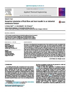
1. Problem Formulation The difference between batch furnaces and continuous furnaces is the furnace structure and the movement of the workload. From the types of continuous furnaces, a virtual continuous furnace is constructed as shown in Fig. 1. It includes furnace wall, retort or muffle, fixture, conveyor, circulation fan and shell cooling. The movement of the furnaces is classified into two kinds: continuous and step by step. Because of the continuous movement of the workload, it is necessary to determine the calculation domain. The selection of the calculation domain should be the maximum load region that repeats the whole process. If there is no fixture, the thermal history of each row of the workpieces in the moving direction can represent the whole load. Thus, just one row of workpieces is taken as the calculation domain. If the workpieces are loaded in the separated fixtures, one row of fixtures can be taken as the calculation domain. The following assumptions are made for the heat transfer in continuous furnace.
765
TRANSACTIONS OF MATERIALS AND HEAT TREATMENT
Vol.25 No.5
*J* The furnace temperature doesn't vary as the production goes in stable condition. But it maybe deviate from the set point temperature as the load volume and speed changes. So the heat balance is checked to see if the furnace power is enough to keep the furnace temperature. Otherwise the furnace temperature will drop to a certain level to maintain the heat balance. «> Heat balance is achieved in each individual zone. *J* The recycling belt or conveyor is always at the same temperature as the fastest heated workpiece. For continuous furnace, the part can be of arbitrary shape and the load pattern can be arranged or randomly stacked. It is the same as batch furnaces.
conduction inside heavy sectioned workpieces. For random load pattern there are two methods, one method is that the random load pattern is assumed to be arranged load pattern virtually and then the method for arranged load pattern can be used. The other one is based on measured results. If experiments can be done to measure the thermal history of the same load pattern, the equivalent thermal conductivity can be acquired by inverse method, i.e., the equivalent thermal conductivity can be calculated by the temperature variation. The equivalent thermal conductivity considers conduction, radiation and convection inside the load. The load is assumed to be a mass with the equivalent thermal conductivity. The equivalent thermal conductivity is then used for the similar load pattern. Here only the heat balance is discussed. 2.1 Heat Balance in Each Zone The furnace temperatures of all zones do not change as the furnace gets into stable condition. So the heat storage in the furnace can be neglected. The heat terms only refer to the heat input, heat absorption by the load and moving accessories and all dynamic heat losses. The heat balance for zone p is (1)
where, Q a) Section view of furnace structure
is the heat input by furnace zone, is the heat absorption by load, Q
heat absorption by fixture,
Q
absorption by belt, Q
is the heat loss from
furnace wall, Q openings, Q Q water, Q
b) Side view of furnace structure Figure 1 Virtual continuous furnace model
2. Mathematical Model The models for the heat transfer between workload and furnace, heat transfer inside the workload, the conduction inside workpiece and also the combustion model for gas-fired furnace can be borrowed from the CHT-fe/4'61. For the arranged load pattern there is radiation between furnace and workpieces, radiation among workpieces, convection between furnace and workpieces, conduction between workpieces and
is the
is the heat
is the heat loss from furnace is the heat loss between zones,
is the heat absorption by shell cooling is the heat input by fan.
All the terms at the right side of the equation (1) are the functions of furnace zone temperature. The heat balance is checked when the load passes through each zone by comparing the needed heat input with the maximum available heat of the furnace zone. (2) where, Q
is the maximum available heat input
of the furnace zone p, T is the zone temperature. If it exceeds the maximum available heat of the furnace zone, the heat balance cannot be kept. Therefore, the furnace temperature will drop to keep the heat balance. 2.2 Calculation of Heat Terms in Furnace Zone/;
766
PROCEEDINGS OF THE
The heat terms in each zone are calculated based on the relationship between calculation domain and zone length. (1) The maximum available heat input by the furnace zone p Q :
(3) where, K^H is the available heat coefficient, qconn is the connected heat input of zone p, Lp is the length of zone p and v is the moving speed. Lp/v is the total time as the calculation domain stays in zone p. (2) Heat release by circulation fan Q :
(4)
where, HPfm is the power of the fan. Here Tp is in Fahrenheit degree. (3) Heat absorbed by the load Q
:
IFHTSE CONGRESS
October 2004
(8) where, (vvc)fix is the product of weight and specific heat of the unit length of belt. Here assume the belt temperature is uniform in each zone and takes the same temperature of the fastest heated workpiece. (6) Heat loss from furnace wall Q :
(9) where, Tg and Ta are the furnace inside surface temperature and the ambient temperature, respectively, tj and kt are the thickness and the heat conductivity of insulation layers, respectively, is the thermal diffusivity from furnace outside to the ambient. (7) Heat loss from the opening Q :
(10)
where, Wdomain is the number of calculation domain in this zone; n n and are the numbers of row, column and layer in the calculation domain, respectively, not the whole furnace zone, i,j, k refers to workpiece number, m denotes time step. /idomain is calculated as
where, cris the Stefan-Boltzmann coefficient, is the emissivity of the furnace wall, Aopen is the opening area. (8) Heat absorption by furnace shell cooling water
where, vwater is the water flow rate, rout and T-m is the outlet and inlet temperatures. (9) Heat transfer between adjacent zones Q :
(6) where, A is the section area between zones. where, ^domain is the length of the calculation domain. (4) Heat absorbed by fixture Q : Fixture is defined here as that directly holds or supports workpieces and moves forward with workpieces. Fixture doesn't include belt or conveyor. They are always at the same temperature as the fastest heated workpieces.
(7)
(5) Heat absorbed by moving belt or conveyor
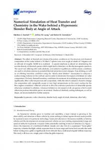
3. Flowchart The flowchart of the model is shown in Fig. 2. The first step is the input of parameters and coefficients and initial conditions such as workpiece information, furnace selection and load pattern. Then the time step is calculated. The following is the heating up of workpieces. It is calculated zone by zone. In each zone the heat balance is checked and the furnace zone temperature is adjusted. Different load patterns are disposed by different methods. As the calculation for all zones is finished, the temperature and heat terms results will be given by profiles and text files. The temperature of every workpiece is given in the text files and can be checked from the profiles.
TRANSACTIONS OF MATERIALS AND HEAT TREATMENT
Vol.25 No.5
Input & initial conditions Calculation of time step Current position
*
Judge the current furnace zone
:
Arranged load pattern
Random load pattern
i Method 1: Method 2: Assumption of arranged load pattern I based on measured results Calculate of column and layer numbers |
lculation of effective thermal I conductivity vity of o the load
767
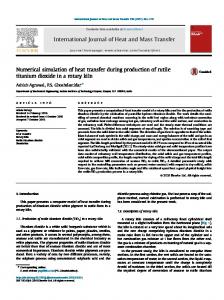
with the forward movement to the continuous furnace. At the middle of zone II, the soaking begins. It can also be seen from Fig. 4 that the center temperature is lower than the surface and corner temperature in the first and second zones. The calculated results are compared with the measured data in Fig. 5. It can be seen they are basically in agreement. If the movement is speeded up from 8.4cm/min to 10.2cm/min, the results of the fastest and slowest temperature curves are plotted together with original results in Fig.6. It can be seen that the soaking time is a little shorter. Therefore the moving speed is a great factor for the heating up process.
Heat transfer in this zone
Radiation between furnace and workpieces Radiation between workpieces Convection between furnace and workpieces Conduction inside the workpieces Conduction between workpieces
Radiation between furnace and outside layer of load Convection between furnace and outside layer of load Conduction inside the load by effective thermal conductivity
Figure 3 The load pattern and location of thermal couples Figure 2 The flowchart of CHT-
4. Case Studies Here the carburizing process of a hook shaped casting, as shown in Fig. 3, is analyzed by CHT-c/. The workpiece information is made of 4140 with weight 0.22kg (0.481bs). The main cycle in this process is carburizing, quenching and tempering. The furnace is a mesh belt continuous furnace made by CanEngineering. The furnace is a three-zone furnace, with a long entrance. The hooks are randomly stacked on the belt, as shown in Fig. 3. The movement speed is 8.4cm/min (3.3 in/min) and the production rate is 684kg/hr (15001b/hr). Endothermic gas is used. Three thermocouples were wired to the workpieces and were placed at the left, middle and right locations in the load, as shown in the Fig. 3. The thermocouples move along with the load in the furnace. The temperature distribution in the workload is shown in Fig.4. The temperature of workload increases
Figure 4 Workload temperature distribution in the continuous furnace
768
PROCEEDINGS OF THE
measured fast easured slow
IFHTSE CONGRESS
October 2004
for continuous furnace. The effect of load pattern and moving speed can be optimized. (3) A case study for the heating up of hooks in a continuous furnace is carried out. The calculated results are compared with the measured results. They are in agreement. And the effect of the moving speed is evaluated.
- - - 'calculated fast •
200
400
600
calculated slow
800
References 1.
zone length (cm)
Figure 5 Comparison of calculated and measured results
2.
3.
4.
5.
6.
Figure 6 Comparison of results at different moving rates
Hill Nandi, Mark Thomson and Mickey Delhunty. Software Tool Optimizes Furnace Design And Operation. Heat Treating Progress, 2002(11): 1-6 HAN Xiaoliang. Calculation and Analysis of Heat Transfer for Batch Heat Treatment Furnace. Industrial Heating, 2001(5): 12-15 (in Chinese) Wang Nini, Zhang Zeyi, Zhang Xinxin and et Al. Mathematical And Analysis Of Main Influence Factors For Steel Tube Annealing Furnace. Industrial Heating, 2004, 33(1): 10-12 (in Chinese) Rong Kevin and Apelian Diran. Computerized Heat Treatment Planning System for Batch Furnaces. Industrial Heating, 2003, 70(10): 27 Kang Jinwu, Vaidya Rohit, Wang Weiwei and Rong Yiming (Kevin). A System for Heat Treating Process Analysis. 2003 ASM Heat Treating Society Conference and Exposition, Columbus, Ohio, USA, Sept. 15-17, 2003 Kang Jinwu and Rong Yiming (Kevin). Modeling And Simulation Of Heat Transfer In Loaded Heat Treatment Furnaces. In: Popoola O, Dahotre N B, Midea S J, Kopech H M, Eds. Surface Engineering: Coating And Heat Treatments, Proceedings. Materials Park: ASM International, 2003, 337-343
5. Conclusions (l)The problem of load heating up process in continuous furnace is formulated in more details, including the furnace structure, movement and load pattern. (2)The heat balance in each individual furnace zone is considered. Furthermore, Based on the heat transfer inside the workload, a program CHT-c/ is developed
Corresponding author. Dr. Kang Jinwu, Email:
[email protected], Mail address: Dept. Mechanical Eng., Tsinghua University, Beijing 100083 China, Tel: +86-10-62784537 Fax: +86-10-62770190