Merit Research Journal of Medicine and Medical Sciences (ISSN: 2354-323X) Vol. 5(5) pp. 248-258, May, 2017 Available online http://www.meritresearchjournals.org/mms/index.htm Copyright © 2017 Merit Research Journals
Original Research Article
Modeling and simulation of lower limb dynamics using simmechanics for potential applications in bilateral prosthesis control Sabreen Abdallah Abdelwahab Abstract
Helwan University, Cairo, Egypt, Production Technology Department E-mail:
[email protected],
[email protected] n.edu.eg
Bilateral transfemoral amputees face many vital problems in normal walking that prevent them from being full-time prosthesis users such as unbalance, instability and increased energy expenditure. They use two prosthetic legs where each leg has a separate control system. In human body, both legs are related to each other and are related to human body while in motion. Consequently, the two prosthetic legs should be controlled using one system. In this work, a SimMechanics model that relates human legs dynamics to each other and to the body in normal walking was developed for further use in bilateral prosthesis control and development. Model inputs are motion data of ankle, knee, and hip joints and the outputs are joints forces and torques. The model showed a good performance when comparing its outputs to the literature bio-mechanics data. Keywords: Human Body Motion, Modeling and Simulation, Simulink, SimMechanics, Human Biomechanics Data, Human Body Metrices, Reverse Dynamics, Lower Limb Dynamics, Bilateral Prosthesis Control
INTRODUCTION Bilateral transfemoral amputees present a real challenge to scientists because amputees at the beginning of using prosthesis fail to use full length prosthesis as they experienced a sever unbalance and instability (Carroll and Richardson, 2009). In order to have a positive prosthesis consequences there are important factors that can result in favorable outcomes for patients (Carroll and Richardson, 2009), these include; getting a peer-to-peer care, having a good physical shape using contented sockets, well residual limbs, ongoing physical therapy, positive family support/involvement, and unwavering commitment from the prosthetic and rehabilitation team.In addition, to have a full motion using two transfemoral prosthesis they are advised to follow a stepped methodology to prosthesis fitting where patients start with short legs and increase the length of the prosthesis gradually to reach the full-length legs. A microprocessorcontrolled swing-and-stance hydraulic knees and energystoring prosthetic feet are used. These knees automatically adapt to the speed, length, and frequency of each step, ensuring the best natural gait pattern probable. This helps amputees in walking on slopes, uneven surfaces, curbs, or stairs (Hafner et al., 2007),
but these knees are controlled separately as each prosthetic leg has its own control system and patients can’t use them directly at the beginning as explained earlier. Hence, a model that can relate the motion dynamics of both legs is needed for robust control of bilateral amputee prosthesis to synchronize their motion and supply patients with better balance, stability and decreasing the rehabilitation period while using different prosthesis lengths to train and balance themselves on full length prosthetic legs.Using one model to present the relation between both legs and their relation to the human body will simplify the control process that targets the amputee safety. Further, in human gait all of hip joint, knee joint and ankle joint are related together. Hence, each prosthetic leg of them shouldn‘t be controlled separately from the other. Moreover, energy requirements are increased for bilateral transfemoral amputee as the body expends 280 percent more energy than that required from a person who is not an amputee (Huang et al., 1979). Hence, this should be taken into consideration while designing the prosthesis in order to provide the required energy through the amputee gait and make the patients have a natural gait without that
Abdelwahab 249
Table 1. Body segments' data
Body segment Upper body Upper leg Lower leg Foot
Shape Cylinder Cylinder Cylinder Rectangular
Mass [Kg] 37.968 5.768 2.4 0.84
2
Inertia [Kgm ] [1.3856 0 0; 0 0.6358 0 ; 0 0 1.3858 ] [ 0.1072 0 0 ; 0 0.0397 0 ; 0 0 0.1072 ] [ 0.0466 0 0 ;0 0.0033 0 ; 0 0 0.0466 ] [ 0.0018 0 0 ; 0 0.0065 0 ; 0 0 0.0079 ]
(a)
(b)
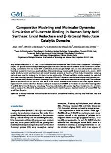
Figure 1. (a) Body segments drawn by AUTOCAD, (b) Body segments in SimMechanics while simulation.
increase in the energy required. Human body modelling can be used in the prosthesis and orthotics design and development (Oçgüder et al., 2012; Jamshidi et al., 2009), humanoid robots design and control (Daumas et al., 2005; Winder and Esposito, 2008), analysis of sportive motion in different sports for sake of optimization (Hubbard et al., 1989; Cavanagh and Lafortune, 1980). A few researchers used external devices to measure body segments' forces and torque by fixing these devices on the segments, this limits the motion and affects the accuracy of the data (Serbest et al., 2015), so more accurate modeling methods should be found and applied. In (Kutilek and Hajny, 2010) the human body motion was measured as angles between body segments and a SimMechanics model is created such that it handles these angles as inputs and outputs the required forces and torques to create these movements by body segments to evaluate the quality of human walking. Segments' weight and moment of inertia can be adjusted according to human body measurements. In (Serbest et al., 2015) a SimMechanics model of human body is developed also, the aims of the model were to calculate the joint torques on the lower limb while daily body movements of sit-to-stand, bend down-stand up, and stair ascending deprived of external help. A link segment model was prepared with respect to
human anthropometric measurements. The aim of this study is to create a SimMechanics model that can simulate human body motion in normal walking for bilateral prosthesis control by synchronizing the motion of both legs and help in delivering the required energy for amputee gait. Then, model validation using human biomechanical data in normal walking will be done with literature data. SimMechanics represents a cost saving modeling method that suits the researchers in the developing country where they can't afford buying the open source software, e.g., OpenSim, Anybody, BoB, etc.that permit realistic geometric representation of the body segments and allow for the insertion of prosthetic components and custom control systems. Modeling Human body segments and joints (Mechanical model). In the model developed in this work the human body was segmented into seven segments including; the upper body segment, two upper leg segments, two lower leg segments, and two foot segments. Segments' masses and inertia are shown in Table 1. The segments are
250 Merit Res. J. Med. Med. Sci.
Figure 2. SimMechanics block diagram.
connected together through joints; the upper body segment is connected to both upper leg segments by right and left hip joints, each upper leg segment is connected to a lower leg segment through the knee joint
as well, each lower leg segment is connected to a foot segment by the ankle joint and the foot tip is connected to the ground or environment through a universal joint. Figure1(a) shows body segments drawn by AUTOCAD.
Abdelwahab 251
Left Leg Ground Reaction Force Components 700 Fz Fy
600 500
Force (N)
400 300 200 100 0 -100 -200
0
0.1 0.2 0.3 0.4 0.5 0.6 0.7 0.8 0.9
1
1.1 1.2 1.3 1.4 1.5
time (sec) Figure 3. Ground reaction force components of left leg.
Left Ankle Angle, Velocity and Acceleration Angle(deg), Velocity(r/s), Acceleration(r/s2)
120 Angle Velocity Acceleration
100 80 60 40 20 0 -20 -40 -60
0
0.1 0.2 0.3 0.4 0.5 0.6 0.7 0.8 0.9
time (sec) Figure 4. Position data of left ankle joint.
1
1.1 1.2 1.3 1.4 1.5
252 Merit Res. J. Med. Med. Sci.
Left Knee Angle, Velocity and Acceleration Angle(deg), Velocity(r/s), Acceleration(r/s2)
150 Angle Velocity Acceleration
100
50
0
-50
-100
0
0.1 0.2 0.3 0.4 0.5 0.6 0.7 0.8 0.9
1
1.1 1.2 1.3 1.4 1.5
time (sec) Figure 5. Position data of left knee joint.
Left Hip Angle, Velocity and Acceleration Angle(deg), Velocity(r/s), Acceleration(r/s2)
40 Angle Velocity Acceleration
30 20 10 0 -10 -20 -30 -40
0
0.1 0.2 0.3 0.4 0.5 0.6 0.7 0.8 0.9
time (sec) Figure 6. Position data of left hip joint.
1
1.1 1.2 1.3 1.4 1.5
Abdelwahab 253
100
Force (N, Moment(N.m)
0 -100 -200 Fz in SimMechanics T in SimMechanics Fy in SimMechanics Fy in literature Fz in literature T in literature
-300 -400 -500 -600 -700
0 0.1 0.2 0.3 0.4 0.5 0.6 0.7 0.8 0.9
1 1.1 1.2 1.3 1.4 1.5 1.6
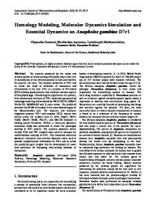
time (sec) Figure 7. Left ankle reaction forces and moment in both literature and simulation.
Modeling technique
Simulation
SimMechanics software is used in system modeling, SimMechanics is using a block diagram modeling technique in designing and simulating engineering systems composed of rigid multi-body machines and represents their motions with Newton equations for forces and torques.
Input data preparation
The developed SimMechanics model In the SimMechanics model each segment is represented by a rigid body block that is defined by its mass, inertia, and coordinate origins and axes for center of gravity. The body initial position and orientation is set, each body is connected to a joint, each joint is actuated by a joint actuator giving the motion data and the resulted force and torque of the joint are tracked using joint sensors (Kinematic mode in simulation). Figure 1 (b) presents body segments in SimMechanics simulation and Figure 2 illustrates the SimMechanics developed block diagram.
Input data for measurements of normal walking in human used in validating the model through simulation are obtained and prepared for the simulation from (Brand, 1992; Winter, 1990), model inputs are the position data for each joint which are angle, velocity and acceleration in addition to the ground reaction force components for each foot, while the output data are force and torque components at these joints. The ground reaction force components are shown in Figure 3. Further, the position data of the ankle, knee and hip joints are shown in Figure 4, Figure 5 and Figure 6, respectively. The motion of both left and right legs are simulated. The developed system is simulated and the force and torque data of each joint are recorded and stored in data files. The cycle time is about 1 second for each step. The step is divided into two major areas the swing phase where the foot is not touching the ground, it is about 40% of cycle time, and the stance phase where the foot is
254 Merit Res. J. Med. Med. Sci.
100
Force (N, Moment(N.m)
0 -100 -200 -300 Fz in SimMechanics T in SimMechanics Fy in SimMechanics Fy in literature Fz in literature T in literature
-400 -500 -600 -700
0
0.1 0.2 0.3 0.4 0.5 0.6 0.7 0.8 0.9
1
1.1 1.2 1.3 1.4 1.5 1.6
time (sec) Figure 8. Left Knee reaction forces and moment in both literature and simulation.
200 100
Force (N), Moment(N.m)
0 -100 -200 -300 Fz in SimMechanics T in Simechanics Fy in SimMechanics Fy in literature Fz in literature T in literature
-400 -500 -600 -700
0
0.1 0.2 0.3 0.4 0.5 0.6 0.7 0.8 0.9
1
1.1 1.2 1.3 1.4 1.5 1.6
time (sec) Figure 9. Left hip reaction forces and moment in both literature and simulation.
Abdelwahab 255
Table 2. RMSE for force and torque components in left joints.
Fz (RMSE) 7.3127 7.9879 13.7837
Left ankle joint Left knee joint Left hip joint
Fy (RMSE) 26.8431 50.2108 163.6531
T (RMSE) 5.2415 5.2415 10.7717
Right Ankle Reaction Force Components and Moment In Simulation 100
Force(N), Moment (N.m)
0 Fz Fy Tx
-100 -200 -300 -400 -500 -600 -700
0
0.1 0.2 0.3 0.4 0.5 0.6 0.7 0.8 0.9
1
time (sec) Figure 10. Right ankle Forces and moment in simulation.
1.1 1.2 1.3 1.4 1.5
256 Merit Res. J. Med. Med. Sci.
Right Knee Reaction Force Components and Moment In Simulation 100
-100
Fz Fy Tx
-200 -300 -400 -500 -600 -700
0
0.1 0.2 0.3 0.4 0.5 0.6 0.7 0.8 0.9
1
1.1 1.2 1.3 1.4 1.5
time (sec) Figure 11. Right knee forces and moment in simulation.
Right Hip Reaction Force Components and Moment In Simulation 100 0
Force(N), Moment (N.m)
Force(N), Moment (N.m)
0
-100 Fz Fy Tx
-200 -300 -400 -500 -600 -700
0
0.1 0.2 0.3 0.4 0.5 0.6 0.7 0.8 0.9
1
time (sec) Figure 12. Right hip forces and moment in simulation.
1.1 1.2 1.3 1.4 1.5
Abdelwahab 257
touching the ground, which is about 60% of the cycle time.
CONCLUSION
The force and torque components of left ankle, knee and hip joints were recorded from simulation, then they were plotted against the real measured values taken from literature in Figure 7, Figure 8 and Figure9 respectively for further comparison. Table 2 showed the Root Mean Squared Error (RMSE) for force and torque components Fz, Fy and T for the left ankle joint, left knee joint and left hip joint. Moreover, the output data for right ankle, right knee and right hip joints were recorded and presented in Figure 10, Figure 11 and Figure 12, respectively.
The model developed in this work was built to simulate the human lower limbs' dynamics in normal waking for the purpose of controlling the human bilateral prosthesis. The model shows the same overall performance of human legs in normal walking. Model inputs are position data and the outputs are the motion dynamics at the lower legs' three joints. Body motion could be animated using the model. The model can be modified by changing the weight and moment of inertia of the body segments.The model could be used to simulate normal walking, running, stair ascending and descending and any human sportive activity depending on the measured biomechanical data. In the next step of this research the model will be applied to the control of human bilateral prosthesis.
DISCUSSION
Conflict of Interest
Figure 7, Figure 8 and Figure 9 represent a comparison between the force and torque components resulted from the model simulation compared to the same data acquired from literature for the left ankle, left knee and left hip joints. In these Figures; Figure 7, Figure 8 and Figure 9 characterize the dynamics of the left ankle, left knee and left hip joints; the vertical force component Fy shows a good tracking to the literature values in stance phase, while a little deviation in swing phase. The horizontal force component Fz shows a good tracking to the literature values in swing phase, while in stance phase it shows a little deviation for the ankle joint. With respect to the torque components, they follow the literature values with a small difference. Table 2 shows the RMSE for the force and torque components related to the three joints. Overall, the Fy component has the higher RMSE and T has the lower RMSE for the same joint. Further, the hip joint has the higher RMSE for the Fz, Fy and T components. These errors may be due to approximating body segments to simple engineering shapes, treating the upper parts of the body as one segment and neglecting the third ground reaction force components as it is too small. The model needs some enhancement to catch all the detailed characteristics of human normal waking. Figure 10, Figure 11 and Figure 12 represent the force and torque components resulted from the model simulation for the right ankle joint, right knee joint and right hip joint. These figures show that the right leg has the same performance such as the left leg but with a time shift. This is reasonable as there is a 50% shift between human legs in motion.
The author has no conflicts of Interest to declare concerning the contents of this manuscript.
RESULTS
ACKNOWLEDGEMENT Thanks to Dr. Mohamed B. Trabia professor of mechanical engineering in Howard Hues collage, Nevada University, Las Vegas for his advises that make this work available. REFERENCES Brand RA (1992). Biomechanics and Motor Control of Human Gait: Normal, Elderly and Pathological. Second Edition, CarrollK and Richardson R (2009). Improving Outcomes for Bilateral Transfemoral Amputees: A Graduated Approach to Prosthetic Success, Advancing Orthotic and Prosthetics care Through Knowledge, 5, No. 2. Cavanagh PR and Lafortune MA, Ground reaction forces in distance running, J Biomech, 13 (1980) 397-406. Daumas B, Xu WL and Bronlund J (2005). Jaw mechanism modelling and simulation, Mech Machine Teor 40:821-33. Hafner BJ, Willingham LL, Buell NC, Allyn KJ, Smith DG (2007). Evaluation of function, performance and preference as transfemoral amputees transition from mechanical to microprocessor control of the prosthetic knee, Arch Phys Med Rehabil. 88: 207-217. Huang CT, Jackson JR, Moore NB, Fine PR, Kuhlemeier KV, Traugh GH, Saunders PT (1979). Amputation: energy cost of ambulation, Arch Phys Med Rehabil. 60 18-24. Hubbard M,Hibbard RL,Yeadon MR and Komor A (1989). A multisegment dynamic model of ski jumping, International Journal of Sport Biomechanics, 5: 258-74. Jamshidi N, Rostami M,Najarian S,Menhaj MB, Saadat- nia M and Firooz S (2009). Modelling of human walking to optimise the function of ankle-foot orthosis in Guillan-Barré pa- tients with drop foot, Singapore Med J 50 412-7.
258 Merit Res. J. Med. Med. Sci.
Kutilek P and Hajny O (2010). Study of human walking by simmechanics, Czech Tech. Univ. Prague, Fac. Biomed. Eng. Czech Repub Oçgüder A,Gِ k H, C Heycan,Tecimel O, Tِnük E and Boz M- kurt (2012). Efects of custom-made insole on gait pattern of patients with unilateral displaced intra-articular calcaneal fracture: evaluation with computerized gait analysis, Acta Orthop Traumatol Turc, 46 17 Serbest K, Çilli M, and Eldoğan O (2015). Biomechanical effects of daily physical activities on the lower limb, Acta Orthop. Traumatol. Turc., 49( 1), 85–90
Winder SB and Esposito JM (2008). Modeling and control of an upperbody exoskeleton, 40 th Southeastern Symposium on System Teory; New Orleans, USA. March 16-18; 263-8. Winter DA (1990). Biomechanics and Motor Control of Human Movement, Fourth Edition, ISBN: 9780470549148, DOI: 10.1002/9780470549148, Winter DA. Biomechanics and Motor Control of Human Movement. 2nd edition. Canada: John Wiley & Sons