Proceedings of the World Congress on Engineering 2010 Vol II WCE 2010, June 30 - July 2, 2010, London, U.K.
Modeling and Simulation of Second-order Phase-locked Loop for Studying the Transient Behavior during Frequency Acquisition and Tracking N. Haque, IAENG Member, P. K. Boruah and T. Bezboruah, IAENG Member
Abstract: The Phase-Locked Loop (PLL) system is used extensively in modern electronic systems such as modems, mobile communications, satellite receivers and television systems. This work presents a method for modeling and simulation of second-order PLL in time domain to study transient behavior during frequency acquisition and tracking. Here we utilize a basic PLL system that consist a multiplier, used as phase detector (PD), a passive loop filter (LF) and a voltage controlled oscillator (VCO). The method combines a circuit level modeling for the LF and mathematical modeling for VCO and the multiplier. For circuit level modeling, the LF is represented by its equivalent companion network model. Transient analysis method for linear dynamic networks is applied for simulating the model of the LF. The complete simulation program, written in Turbo C language, combines the circuit level modeling of LF with the mathematical modeling of multiplier and the VCO. The MATLAB program is used for graphical analysis of data to observe transient behavior of PLL system. The nonlinear cycle slip phenomena occurred during acquisition process is observed. The transient response at locked condition with reference to step change in input frequency and step change in input phase verifies the mathematical descriptions of the PLL system. Key words: The Phase-Locked Loop, PLL Frequency acquisition, PLL Tracking, Cycle slip, Companion network model.
N.Haque, with the Department of Electronics & Telecom Engineering, Prince of Wales Institute of Engg. & Techmology, Jorhat-785001, Assam, INDIA (E-mail:
[email protected], Tel: 94350-12060) P.K.Boruah, with the Department of Instrumentation & USIC Gauhati University, Guwahat-781014, Assam, INDIA (E-mail:
[email protected] , Tel: +91-361-2674537) T. Bezboruah, with the Department of Electronics & Communication Technology Gauhati University, Guwahati-781014, Assam, INDIA (E-mail:
[email protected], Tel: +91-36-2671262,)
ISBN: 978-988-18210-7-2 ISSN: 2078-0958 (Print); ISSN: 2078-0966 (Online)
I. INTRODUCTION
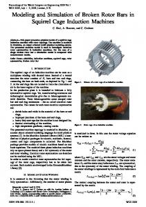
Understanding the transient behavior of PLL during acquisition and tracking is an important aspect in many applications. Block diagram of PLL is shown on Fig.1. The theories of PLL systems have been analyzed in details in the literature [1-7]. It is observed that the PLL is already well established by its theoretical work and practical application.
Fig.1 Block diagram of PLL However different methods may be applied for studying and for further improving various performance parameters of PLL. The motive behind this work is to study the transient behavior of PLL with proper choice of LF components and with different types of signals and frequencies in time domain. The work is based on companion model [9] representation of circuit elements which are used in SPICE and SPICE-like simulator programs. II. BRIEF OVERVIEW OF PLL BEHAVIOR A PLL is electronic systems which can phase lock an internal oscillator signal i.e. the output of VCO with the reference signal. The phase error between internal oscillator signal and the reference signal is quantified by the multiplier used as phase error detector. The output of the phase error detector is processed by the loop filter and the results are applied to the input of the VCO. The output of the loop filter controls the phase and frequency of the VCO.
WCE 2010
Proceedings of the World Congress on Engineering 2010 Vol II WCE 2010, June 30 - July 2, 2010, London, U.K.
If the reference input and VCO frequencies are not equal, the output of the LF will be an increasing or decreasing voltage depending on which signal has the higher frequency. This change in frequency is tracked by a change in the loop filter output, and thus forcing the VCO free running frequency to capture the reference input frequency. In the acquisition mode, which has non linear behavior, the PLL system is either out of lock or just starting up to lock with the input reference signal. In tracking mode, the PLL is already locked and it tries to maintain the locking condition in the situation of sudden change of phase and frequency of the input reference signal. If the changes are small, the PLL can manage the disturbances so that it can come back to the steady state. III. MODELING OF PLL COMPONENTS
A. Multiplier as Phase Detector
The two input signals to the phase error detector are as follows: (1) x i ( t ) Ai cos i t i
dv c dt
(4)
This derivative is approximated numerically by using the backward Euler formula [8]. Backward Euler offers a good compromise of accuracy and stability dv v n 1 v n (5) n 1 dt t t t n 1 t n Where the “n” superscript refers to a particular time and it is assumed that the difference between successive time steps is constant i.e. (6) t n 1 t n T Where, T is called the time step or step size. Now Eq.4 is approximated by using Eq.5 as ic
(2)
Where Ai and Bv are the amplitudes of input reference and VCO signal, ωi and ωv are the angular frequencies of input reference and VCO signal, өi and өv are the input and VCO phase respectively. The loop filter removes the high frequency component from multiplier output and the output of the loop filter is approximated [1] as:
1 Ai Bi sin( i v ) 2 K d sin( )
companion model [9], [10]. The method transforms capacitor by applying a numeric integration to the currentversus-voltage relationship of a capacitor i.e. ic C
The three components of PLL system are considered for its equivalent representation before simulation. The PD and the VCO are represented in its mathematical relationship and the loop filter is being implemented at the component level. So the PLL as a system will be simulated as a combination of mathematical and circuit level modeling.
xv (t ) Bv cosvt v
Fig.2. Loop filter
n 1
C
v
n 1
v
n
(7)
T
The current Ic(n+1) is an approximation to the true capacitor current. The linear companion model representation for a capacitor follows from Eq.7 by viewing this equation as a Kirchhoff’s Current Law (KCL) sum at a branch node as shown in the Fig.3.
Ic
n 1
Vc
(3)
Where ø is phase difference and Kd is the PD gain in Volts/radian. The phase difference ø plays a prominent role in PLL analysis and PD gain is important as one of the design parameters of the closed loop gain. B. Loop filter The most common type of LF that is normally used in linear PLL system is of Lag-lead type as shown in the Fig.2. This filter circuit is of linear dynamic type and its equivalent is represented by transient solution method of linear dynamic network [8]. The charge-storage element capacitor must be reduced to simplified equivalent circuit known as
ISBN: 978-988-18210-7-2 ISSN: 2078-0958 (Print); ISSN: 2078-0966 (Online)
v n 1
C
G=C/T
Ieq G.vn
Fig.3. Companion model of Capacitor Conductance G describes the part of C’s current dependent on its new voltage v (n+1). Current source Ieq=G.v n describes the other part based on the past voltage. Since vn is the node voltage from previous time step and remains fixed, only v(n+1) changes with each new iterative voltage value and Ic(n+1) changes to become the linear I-V relation for the new capacitor voltage at that transient time-step. At each discrete time point, the numeric integration determines the linear I-V relationship for the capacitor.
WCE 2010
Proceedings of the World Congress on Engineering 2010 Vol II WCE 2010, June 30 - July 2, 2010, London, U.K.
Fig.4. Companion model of Resistor The value of the resistor is represented by its conductance value in the system matrices. Fig.4. represents the I-V characteristics of a resistor and its equivalent conductance value C. Voltage Controlled Oscillator Instantaneous angular frequency ωv of the VCO is a linear function of the control voltage vc with reference to the free running angular frequency ω0 and the VCO produces a sinusoidal signal. Mathematically,
v 0 K v vc t
v c t
v o Kv
(8) (9)
In the Eq.9, Kv is the VCO gain parameter and it has the unit of radians per second. The frequency of oscillation of the VCO changes by Kv radians per second for every volt of control voltage vc(t) applied as input. IV. SIMULATION METHOD The method presented here, simulates the PLL system in time domain. The nodal equations for loop filter are represented in a set of matrices as [G][V]=[I] and it characterizes the linear representation between the voltage and current for every element in the circuit. The simulation program is written in Turbo C language for the complete PLL System. The program iterates for the element of voltage in the set of matrices over and over again until a set of voltage is found that satisfies the nodal equations of the low pass filter. The iteration is based on Gauss-Sidel technique [11] and it makes use of the fact that a non-linear device can be treated as linear over a small range. GaussSeidel technique is an advantageous approach because it allows the user to control round-off error that is inherent in elimination methods such as Guassian elimination.
Fig.5 Frequency acquisition at 500 KHz zero. Here we observe that the VCO control voltage vc(t) pushes VCO free running frequency ω0 towards instantaneous angular frequency ωv of the VCO. Finally ωv of the VCO becomes frequency and phase locked with input reference frequency ωi during steady state. Fig.5 shows that VCO control voltage attains steady state after about 2000 time steps and the frequency difference approaches towards zero. As the initial frequency difference increases, the gain of multiplier is reduced due to increased phase error. Fig.6 shows the Frequency acquisition range of 747 KHz without cycle slip and the Fig.7 shows the same for 748 KHz causing a cycle slip with phase error beyond 1800. It shows the acquisition or capture range of PLL for the selected values as 747 KHz. The theoretical acquisition range for the same selected values as per references [2-5] is 713 KHz.
V. RESULT AND DISCUSSION The simulation time step size used in this work is 1 nano second. LF component values are R1=68K, R2=2 K and C=10nF. A. Frequency acquisition We set (as per Eq.8) ω0= 10MHz and Kv =10 MHz. As per Eq.9, the VCO control voltage vc(t) should be 0.05 volt so that the initial frequency difference of 500 kHz reduces to ISBN: 978-988-18210-7-2 ISSN: 2078-0958 (Print); ISSN: 2078-0966 (Online)
Fig.6 Frequency acquisition at 747 KHz slip
without
cycle
WCE 2010
Proceedings of the World Congress on Engineering 2010 Vol II WCE 2010, June 30 - July 2, 2010, London, U.K.
.
Fig.7. Frequency Acquisition at 748 KHz with cycle slip B. Tracking behavior A phase step of 450 is applied at 8000 time steps at the input reference signal when the PLL is in steady state as shown in Fig.8. The VCO control voltage again attains steady state after about 22000 time steps and also the frequency difference approaches zero. So, the PLL is able of tracking out the sudden change of input phase as per theoretical formulations. A frequency step of 20 KHz is applied at 8000 time steps at the input reference signal when the PLL is in steady state as shown in Fig.9. We observe that the VCO control voltage changes due to the step input and the frequency difference approaches towards zero. Finally the VCO output signal becomes synchronized with the input reference signal at the steady state. So, the PLL is able of tracking out the sudden change of input frequency.
Fig.9. Input frequency step of 20 KHz at 8000 time step VI CONCLUSION In this paper we have observed that the circuit level simulation of companion model of loop filter along with mathematical formulations of multiplier and VCO may be used for simulation of analog PLL to investigate its transient behavior in time domain. The simulation program uses uniform time steps size. Data generated from simulation program has been analyzed using MATLAB program. The practical simulated value of Frequency acquisition range is almost similar with the values known from literature of PLL. Tracking behavior due to input phase step and frequency step also shows the results as per theoretical formulations. This work may be further observed to study the steady-state probability density function of phase error behavior [4] under the influence of Additive White Gaussian Noise (AWGN).
ACKNOWLEDGEMENT The authors would like to thank Department of Electronics & Communication Technology (ECT), Gauhati University, Guwahati for encouragement towards the present work. They are grateful to the Head of the Department of ECT, Gauhati University for providing infrastructural support for this research work. Moreover, the authors would like to thank the Department of Electronics & Communication Engineering, Indian Institute of Technology, Guwahati for providing its laboratory and library facilities. Fig.8. Input Phase step of 450 at 8000 time step ISBN: 978-988-18210-7-2 ISSN: 2078-0958 (Print); ISSN: 2078-0966 (Online)
WCE 2010
Proceedings of the World Congress on Engineering 2010 Vol II WCE 2010, June 30 - July 2, 2010, London, U.K.
REFERENCES [1] G.Hsieh and J.C.Hung, “Phase-Locked Loop Techniques-A Survey, IEEE Transactions on Industrial Electronics, Vol. 43, pp 609-615 No.6, December 1996. [2] V.F.Kroupa, Phase Lock Loops and Frequency Synthesis, John Wiley & Sons, 2003 [3] Floyd M. Gardner, Phaselock Techniques. John Wiley &Sons, 1979 [4] John L. Stesnby, Phase-Locked Loops: Theory and Applications, CRC Press, 1997 [5] P.V.Brennan, Phase-locked Loops: Principles and Practice, Macmillan Press Ltd, 1993. [6] Jack Smith, Modern Communication Circuits, Tata McGraw-Hill Edition, 2003 [7] John & Martin, Analog Integrated Circuit Design,John Wiley & Sons,1996 [8] R.Raghuram, Computer Simulation of Electronic Circuits, Wiley Eastern Ltd. 1991 [9] Ron Kielkowski, Inside SPICE, McGraw-Hill, Inc, 1998 [10] Donald A. Calahan, Computer- Aided Network Design, TMH Eddition, 1979. [11] V.Rajaraman, Computer Oriented Numerical Methods, Prentice Hall of India Pvt. Ltd. 1998 [12] Rui He, Jun Li, Woogeun Rhee, and Zhihua Wang, Transient Analysis of Nonlinear Settling Behavior in Charge-Pump Phase-Locked Loop Design, pp 469-3472, 2009 IEEE [13] A. Telba, Modeling and Simulation of Wideband Low Jitter Frequency Synthesizer, pp 317-319, 2009 IEEE
ISBN: 978-988-18210-7-2 ISSN: 2078-0958 (Print); ISSN: 2078-0966 (Online)
WCE 2010