Journal of Electrical Engineering www.jee.ro
MODELING AND SIMULATION OF SPEED CONTROL OF INDUCTION MOTOR BY SPACE VECTOR MODULATION TECHNIQUE USING VOLTAGE SOURCE INVERTER C.DINAKARAN Assistant Professor, Department of EEE, Sri Venkateswara College of Engineering & Technology, Chittoor, A.P, India
[email protected] Abstract: In this paper, v/f control of Induction motor is simulated for closed loop systems. The induction motor is fed from three phase bridge inverter which is operated with space vector modulation (SVM) Technique. Among the various modulation strategies, Space Vector Modulation Technique is the efficient one. Because it has better spectral performance and output voltage is closer to sinusoidal. The performance of SVM technique and Sine triangle pulse width modulation (SPWM) technique are compared for harmonics, THD, DC bus utilization, output voltage and observed that the Space Vector Modulation has better performance compared to SPWM. These techniques are applied for speed control of Induction motor by v/f method for closed loop systems. It is observed that the induction motor performance is improved with SVM and verified by using MATLAB/SIMULINK, PROTEUS Software and Hardware Prototype Model.
control of Induction Motor for closed loop systems using SVM technique. The SVM is simulated compared with the conventional SPWM technique and performance of Induction Motor is improved [13] – [16]. With the SVM performance is improved in Induction Motor because it eliminates all the lower order harmonics in the output voltage of the inverter (stator voltage of the Induction Motor) when compared to the conventional SPWM technique. The performance of the Induction Motor can be further improved by eliminating the current harmonics in the stator currents of the Induction Motor [17] – [20]. 2. Space Vector Modulation
Key words: Space vector modulation, SPWM, v/f control of Induction motor, PIC Controller, Induction Motor Drive.
1. Introduction Power Electronic switches with low cost computational hardware of induction motor compare with DC motors such as power to weight ratio, acceleration performance, maintenance, operating environment and higher operating speed without the mechanical commutator, cost and robustness of the machine and perhaps control flexibility are often reasons for choosing induction machine drivers in small to medium power range applications [1] – [3]. Fast switching power semiconductor devices and machine control algorithm are more precise PWM (Pulse Width Modulation) method [4] – [6]. A large variety of methods for PWM exists for the AC machine drive application, full utilization of the DC bus voltage is extremely important in order to achieve the maximum output torque under all operating conditions [7] – [8]. The speed and torque of an induction machine can be controlled by various modulation strategies for inverter [9] – [12]. In this paper v/f
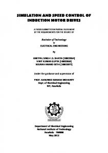
Fig. 1 Three Phase Inverter Fed Induction Motor
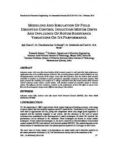
Figure 1 shows the typical power stage of the three phase inverter and the equivalent circuit of a machine are presented. The voltages applied to machine is defined as Van, Vbn, Vcn and Van, Vbn , Vcn denotes the pole voltages produced in the inverter stage in this paper. Eight different switching states of the three phase inverter are depicted as shown in Figure 2. All the machine terminals are connected to each other electrically and no effective voltages are applied to machine when the zero vectors presented by V0 and V7 are selected. Six voltage vectors can be selected to apply
1
Journal of Electrical Engineering www.jee.ro
an “effective voltage” to the machine and these vectors can be located on the vector space represented with the stator fixed d-q reference frame as shown in Figure 3.
considered as the effective vectors to generate desired output voltage. The relationship between the switching variable vector [ , , ] and the line-to-line current vector [ , , ] can be expressed in Equation (1), =
1 −1 0 0 1 −1 −1 0 1
(1)
Also, the relationship between the switching variable vector [ , , ] and the line to neutral current vector [ , , ] can be expressed in Equation (2). =
2 −1 −1 −1 2 −1 −1 −1 2
(2)
3. Switching Factor and Vector Selector
Fig. 2 Voltage Switching State Vector
Fig. 4 Gating signal pattern of the space vector PWM (Upper Switching Vector - 1)
Fig. 3 Effective Vectors of the Space Vector diagram
If a constant reference voltage vector V*or Vref is given in one sampling period, this vector can be generated using zero vector (V0 or V7 ) in combination with only two nearest active vectors (Vn and Vn+1). These two active vectors are
Fig. 5 Gating signal pattern of the space vector PWM (Lower Switching Vector - 1)
Figure 4 & 5 shows the relationship between the effective times and the actual gating times is depicted when the reference vector is located in the
2
Journal of Electrical Engineering www.jee.ro
Sector-1. In this case the V1 vector is applied to the inverter during T1 interval and consequently V2 vector is applied during T2 interval. In the three phase symmetry modulation method, the zero sequence voltage vectors is distributed symmetrically in one sampling period to reduce the current ripple. Thus, in general the switching sequence is given by 0-1-2-7-7-2-1-0 within two sampling periods. With the point of view of the upper switching devices of one inverter leg, the former sequence (0-1-2-7 sequence) is called ‘ON’ sequence and the latter (7-2-1-0) is called ‘OFF’ sequence as shown in Table I. The conventional space vector modulation task can be solved into following steps to make the actual PWM pattern. Sector Identification: By comparing the stationary frame d-q components of the reference voltage vector, the sector where the reference vector is located is identified. Calculating the Effective Timer: Using the d-q components of reference vector and the DC link voltage information, the effective times T1, T2 are calculated. Determining the switching Times: The corresponding sector information of actual switching time for each inverter leg is generated from the combination of the effective times and zero sequence time.
SIMULINK using the following mathematical model. Switching time duration of any vectors are expressed as, ∗
∗√
∗
∗√
= =
∗
=
sin
−
sin
−
∗ √3
sin
Sector
1
2
3
4
5
6
Upper Switch ( , , ) = = = = = = = = = = = = = = = = = =
+ + ⁄2 + ⁄2 ⁄2 + + ⁄2 + ⁄2 ⁄2 + + ⁄2 + ⁄2 ⁄2 + + ⁄2 + ⁄2 ⁄2 + + ⁄2 + ⁄2 ⁄2 + + ⁄2 + ⁄2 ⁄2
Lower Switch ( , , ) = = = = = = = = = = = = = = = = = =
+ + ⁄2 + + ⁄2 + + ⁄2 + + ⁄2 + + ⁄2 + + ⁄2
+ ⁄2
⁄2
+ ⁄2
⁄2
+ ⁄2
⁄2
+ ⁄2
⁄2
+ ⁄2
⁄2
+ ⁄2
⁄2
(3) (4)
∗ cos
3
− cos
3
∗ sin
(5) ∗
= ∗
=
∗√ ∗√
sin − cos
−
(6)
∗ sin
+ cos
∗ sin
(7) +(
=
)
+
(8)
According to Krause’s Model equation in flux linkages are expressed as, =
−
=
+
+
=
−
=
+
+ (
+
)
(
(
(9) )
(10)
+
(11)
+
) (12)
+
+
)
(
+
To convert Three phase voltages in two phase synchronously rotating frame are first converted to two phase stationary rotating frame are expressed in equations (13) & (14), (
TABLE I: SWITCHING FACTOR (Upper & Lower Vector)
+
cos ⎡cos ⎢ ( = ⎢ sin sin ⎢ ⎣ 1 0 0 = 0 √
) )
cos sin
(
)
(
)⎥
⎤ ⎥ ⎥ ⎦
(13)
(14)
√
5. Variable Frequency of Induction Motor
4. Mathematical Model of Induction Machine The induction machine is implemented by
V/f control is an open loop scalar control for Induction Motor (IM). Instability of a V/f controlled IM drive system may occur as the V/f control method has no means of controlling the transient operation of the drive system. These approaches are somewhat for high damping IM drive systems and are based on current feedback to improve the stability of the conventional V/f control as shown in Figure 6. This method enables the damping of the low frequency oscillations in V/f control. However, applying this method for high voltage IM resulted in more oscillations and lead to a highly unstable drive
3
Journal of Electrical Engineering www.jee.ro
system. A detailed analysis of the causes of this instability is carried out. A theoretical analysis of the system has shown that the low damping factor of high voltage IM is the origin of these oscillations. These oscillations have made the improved V/f as shown in Figure 7.
the corresponding Simulation results gating signals for Upper and Lower Switching Vector as shown in Figure 11 & 12.
Fig. 8 Subsystem for PWM
Fig. 6 Induction Machine Connected to V/f Source
Fig. 9 Simulation Circuit for speed control of Induction Motor
Fig. 7 Sequence of
( )
and
( )
Control based on current derivatives unstable for motors with low damping factor. This low damping factor is due to the small value of the stator and rotor resistances of High power Induction Motor.
Fig. 10 Subsystem of Pulse Generator
6. Experimental Results A. Simulation Result:
The proposed method has been tested and simulation results are shown Figure 8, 9 & 10. This model has been implemented using MATLAB/SIMULINK environment with SIMPOWER system toolbox. Using PWM methods
Fig. 11 Gating Signal for Upper Switching Vector
4
Journal of Electrical Engineering www.jee.ro
Fig. 12 Gating Signal for Lower Switching Vector
The output describes the selection of each sector for applying switching pulse to inverter as shown in Figure 13.
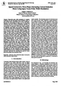
Fig. 16 Electromagnetic Torque
Figure 16 shows us the waveform variation for the Electromagnetic Torque. The average torque value to be around 17 Nm. Figure 17 & 18 shows the rotor and stator current of Induction Motor using Space Vector Modulation.
Fig. 13 Selection of Sector Fig. 17 Rotor Current
Fig. 18 Stator Current Fig. 14 Rotor Speed
Fig. 19 Space Vector Modulation Fig. 15 Rotor Angle
Figure 14 represents the speed of Induction Motor. The speed variation is in the range of 1495.5 rpm which is equal to the synchronous speed and rotor angle as shown in Figure 15.
The output describes the space vector modulation is based upon the space vector representation in the d, q plane as shown in Figure 19. The switching patterns of each pulse in given in Figure 20.
5
Journal of Electrical Engineering www.jee.ro
The output describes the Rotor Speed and Stator angular electrical frequency by using steady state condition Wr=314 rad/sec comes at 0.3 seconds as shown in Figure 21. The electrical torque and no load torque condition, the electrical torque at steady state will be at zero condition. While applying TL=0 Nm, the torque will be at steady state condition Te=0 Nm as shown in Figure 22. The THD of this system is 1.99% is determined by using FFT analysis as shown in Figure 23.
Fig. 20 PWM Signal
Fig. 23 Total Harmonic Distortion B. PROTEUS MODEL
Proteus is one of the most famous simulators. It can be used to simulate almost every circuit on electric fields. It is easy to use because of the Graphical User Interface (GUI) that is very similar to the real prototype board. Moreover, it can be used to design printed circuit board (PCB). Figure 24 shows the Induction Motor designed in Proteus model and the output pulses are given in Figure 25. Q12
Q8 2N3859A
D5
D9
2N3859A
Q10
DIODE
D7
2N3859A
DIODE
Fig. 21 No Load Rotor Speed, Stator angular electrical
A
DIODE
B C
+88.8
D
frequency, Electrical output Torque, Load Torque
V1 12v
K1 K OP : GAIN
Q9 2N3859A
Q11 D6
Q13
D8
2N3859A
2N3859A
D10
DIODE
DIODE
DIODE A B A
C
B
D
C D
U6(MCLR/Vpp/THV)
D19(A)
D19 3 10 11
U6 13 14 2 3 4 5 6 7 8 9 10 1
OSC1/CLKIN OSC2/CLKOUT
RB0/INT RB1 RB2 RA0/AN0 RB3/PGM RA1/AN1 RB4 RA2/AN2/VREF-/CVREF RB5 RA3/AN3/VREF+ RB6/PGC RA4/T0CKI/C1OUT RB7/PGD RA5/AN4/SS/C2OUT RC0/T1OSO/T1CKI RE0/AN5/RD RC1/T1OSI/CCP2 RE1/AN6/WR RC2/CCP1 RE2/AN7/CS RC3/SCK/SCL RC4/SDI/SDA MCLR/Vpp/THV RC5/SDO RC6/TX/CK RC7/RX/DT RD0/PSP0 RD1/PSP1 RD2/PSP2 RD3/PSP3 RD4/PSP4 RD5/PSP5 RD6/PSP6 RD7/PSP7
33 34 35 36 37 38 39 40 15 16 17 18 23 24 25 26
12
VC
R12 100
U8 DIODE VB
SD
HO VS LIN COM LO
6 7 5 1
D18(A) D1(A)
D18
R1
D1 U1 DIOD E
VC
VB
6
COM
7 HO 5 VS 1 LO
3 10
10 11 12
HIN SD LIN
R11
2
11 12
HIN
LIN
R2
6
VB
COM
7 HO 5 VS 1 LO
SD
D2
U7 DIOD E
VC
IR2112
U2 E DIOD
3 10 11 12
2
IR2112
U2(VC)
100
100
3
2 19 20 21 22 27 28 29 30
HIN
HIN
VC
SD LIN COM
VB HO VS LO
100
6 7 5 1
D3
U3(VC)
U3 E DIOD
3 2
U4(VC)
R3
IR2112
D4
100
R4
IR2112 10 11 12
HIN
VC
SD
VB
HO VS LIN COM LO
6 7 5 1
11 12
2
IR2112
UDIOD 4 E
3 10
HIN
VC
VB
LIN COM
HO VS LO
SD
100
6 7 5 1
PIC16F877A 2
Fig. 22 Rotor Speed and Load Torque
IR2112
Fig. 24 Development of Brushless DC Motor in PROTEUS Software
6
Journal of Electrical Engineering www.jee.ro
Fig. 28 Input waveform
Fig. 25 Output Pulse C. Hardware Model
The hardware is implemented for design of a space vector modulation induction motor as shown in Figure 26. Gate driver IC IR2112 circuits are used for boosting the speed which will get from a PIC Microcontroller (PIC 16F877A) is used for generating required pulse as shown in Figure 27. Figure 28 & 29 gives the input and output waveforms of space vector modulated inverter. Generally the Induction Motor speed is measured by Tachometer in Space Vector Modulation Technique the value of the speed is 1480 rpm.
Fig. 29 Output waveform
Table II compares the performance details of space vector modulation techniques using Induction Motor. TABLE II Simulation Results
1.99
Speed (rpm) 1495.4
Proteus Model
2.34
1476
18
Hardware Setup
2.42
1472
24
% THD
Computation Time (Sec) 10
7. Conclusion
Fig. 26 Experimental Setup for Speed Control of Induction using SVM Motor
Space Vector Modulation (SVM) technique and sinusoidal Pulse Width Modulation (SPWM) technique has been implemented using MATLAB/SIMULINK, PROTEUS and Hardware Model. The v/f control of Induction motor drive for closed loop system has been simulated. The transient behavior of the same motor operated with fixed supply voltage. It is observed that SVM generates less harmonics distortion in the output voltage and more efficient use of supply voltage in comparison with SPWM and hence Motor performance is improved. This paper can be enhanced with variable voltage and variable frequency control for induction motor operation individually. The proposed scheme by the combination of V/f control using rotor speed measurement for flux calculation.
Fig. 27 Gate pulse of the controller circuit
7
Journal of Electrical Engineering www.jee.ro
References [1] HongWu She, Hue Lin, Bi He, Xingwei Wang, Limin Yue and Xing An, “Implementation of Voltage – Based Commutation in Space Vector – Modulated Matrix Converter,” IEEE Trans. Ind. Elec., Vol. 59, No. 1, PP. 154 – 166, Jan. 2012. [2] Ning Zhu, David Xu, Bin Wu, Navid R.Zargari, Mahrdad Kazerani and Fangrui Liu, “Common – mode Voltage Reduction Methods for Current – Source Converters in Medium – Voltage Drives,” IEEE Trans. Power Electronics, Vol. 28, No. 2, pp. 995 – 1006, Feb. 2013. [3] V.Anantha Lakshmi, M.Surya Kalavathi, V.C.Veera Reddy, “Space Vector Based Hybrid PWM Algorithm for Direct Torque Controlled Induction Motor Drives for Reduced Common Mode Voltage,” Journal of Electrical Engineering, Vol. 12, Edi. 3, PP. 65 – 72, No. 3, Dec. 2012. [4] Behrooz Mirafzal, Mahdi Saghabeini and Ali Kashefi Kaviani, “An SVPWM – Based Switching Pattern for Stand – Alone and Grid – Connected Three – Phase Single – Stage Boost Inverter,” IEEE Trans. Power Electronics, Vol. 26, No. 4, PP. 1102 – 1111, Apr. 2011. [5] Seyed Mohammed Dehghan Dehnevi, Mustafa Mohamadian, Aliyazdian and Farhand Ashrafzadeh, “Space Vectors Modulation for Nine – Switch Converters,” IEEE Trans. Power Electronics, Vol. 25, No. 6, PP. 1488 – 1496, June 2010. [6] Shuitao Yang, Fang Z.Peng, Qin Lei, Ryosuke Inoshita and Zhaoming Qian, “Current – Fed Quasi – Z – Source Inverter with Voltage Buck – Boost and Regeneration Capability,” IEEE Trans. Ind. Applications, Vol. 47, No. 2, PP. 882 – 892, Mar./April 2011. [7] H.She, H.Lin, X.Wang and L.Yue, “Vector Control of Induction Motor Based on Output Voltage Compensation of Matrix Converter,” in Proc. IEEE ECCE, 2010, pp. 1851 – 1858. [8] Z.Wang, B.Wu, D.Xu and N.Zagari, “Hybrid PWM for high – power Current-SourceInverter-fed drives with low switching frequency,” IEEE Trans. Power Electronics, Vol. 26, No. 6, pp. 1754 – 1764, Jun. 2011. [9] A.M.Hava and E.Un, “A High Performance PWM Algorithm for Common Mode Voltage Reduction in Three – Phase Voltage Source Inverters,” IEEE Trans. Power Electronics, Vol. 26, No. 7, pp. 1998 – 2008, July 2011. [10] Fatiha Zidani and Rachid Nait Said, “Direct Torque Control of Induction Motor with Fuzzy Minimization Torque Ripple,” Journal of Electrical Engineering, Vol. 56, No. 7 – 8, PP. 183 – 188, 2005.
[11]
[12]
[13]
[14]
[15]
[16]
[17] [18]
[19]
[20]
D.Chandra Sekhar and G.V.Marutheshwar, “Modeling and Direct Torque Control of Induction Motor by using Fuzzy Logic Control Technique,” Journal of Electrical Engineering, PP. 1 – 10. K.Zhou, D. Wang, “Relationship between Space Vector Modulation and three phase carrier-based PWM: A comprehensive analysis,” IEEE Trans. Ind. Elec. Vol. 49, pp 186-196, Feb. 2002. Jack Daming Ma, Member, IEEE, Bin Wu, Senior Member, “A Space Vector Modulated CSI-Based AC Drive for Multi motor Applications”, Vol. 16, NO. 4, July 2001. G. Amler, “APWMcurrent-source inverter for high quality drives,” EPE J., vol. 1, no. 1, pp. 21–31, July 1991. W. Shepherd and J. Stanway, “An experimental closed-loop variable speed drive incorporating a thyristor driven induction motor,” IEEE Trans. Ind. Gen. Applicat., vol. IGA-3, pp. 559–565, Nov./Dec. 1967. I. Miki, O. Nakao and S. Nishiyama, “A new simplified current control method for fieldoriented induction drives,” IEEE Trans. Ind. Applicat., vol. 27, pp. 570–1081, Nov./Dec. 1991. S.R.Bowes, “New sinusoidal pulse width modulation inverter,” Proc. Inst. Elect. Eng., vol. 122, pp. 1279-1285, 1975. D.C Lee.G-M.Lee, “A Novel over modulation technique for space vector PWM inverters,” IEEE Trans. 1997. J.Holtz, “Pulse width modulation for electronic power conversion”, Proc. IEEE, vol.82, pp 1194- 1214, Aug. 1994. J.Holtz, “Pulse width modulation-a Survey,” in Proc. IEEE PESC’92, 1992, pp.11-18.
8