IEEE International Symposium on Industrial Electronics (ISlE 2009) Seoul Olympic Parktel, Seoul, Korea July 5-8, 2009
Modeling and Simulation of Synchronous Machine and its behaviour against Voltage Sags Daniel Aguilar', Alvaro Luna, Alejandro Rolan, Gerardo Vazquez
Gustavo Acevedo
Electrical Department of Engineering Technical University of Catalonia Colom 1- 08222- Terrassa, Spain 'Contact Author:
[email protected]
Electrical Department of Engineering and Power Systems Federal University of Pernambuco (UFPE) Recife, Pernambuco Brazil
Abstract- This paper studies the effects of voltage sags (dips), both symmetrical and unsymmetrical, on the three-phase Synchronous Machine (SM). The vast majority of the electrical power generation systems in the world is consist of synchronous generators coupled to the electrical network though a transformer. Voltage sags on SM cause speed variations, current and torque peaks and hence may cause tripping and equipment damage. The consequences of voltage sags in the machine behaviour depends on different factors such as its magnitude (or depth), duration and initial point-on-wave, and also on the parameters of the machine. In this study, three machines of different nominal power have been used for simulate on MATLAB the effects of the voltage sags on the machine under specific conditions.
1.
SM is essential in order to obtain a reliable analysis of stability and dynamical performance. The aim of this paper is simulate the SM and analyze its behaviour against voltage sags. Section II presents the SM model. Section III shows the voltage sags classification. Finally, based on the simulations using MATLAB, voltage sags effects on SM are analyzed in Section IV. II. SYNCHRONOUS MACHINE MODEL In this paper the SM generic model is used considering its dynamic equations in the dq reference frame given by [6]. Damper winding exist in both d and q axis:
INTRODUCTION
(1)
The electricity is the main source of energy nowadays in our society. It is used to provide the energy needed for operating a great variety of industrial processes, lighting and transportation as well as for the information and communication technologies [1]. The Synchronous Generator (SG) has been widely used for this purpose around the world due to its capability of generating electricity in large scale power plants. In addition, small synchronous generators, in the kVA range, are often used as well in an isolated system where the generator is driven with a small combustion engine as a prime-mover. These can be used as emergency power sources for hospitals, the military facilities and in the industry in case of a blackout. Moreover, the firsts wind turbines based on SG are directly coupled to the grid (fixed speed generation systems), although the progress in the static converter technology, has transformed this generation systems though variable speed operation, allowing the optimum power efficient for a wide wind speed range [2]. During the last years, the power quality has gained a great importance in both industry and in research. The grid may present many types of disturbances, being the voltage sags the most common ones. A voltage sag is a short-duration (from half cycle to 1 minute) drop between 10% and 90% in the magnitude of the rms voltage. The interest in studying this kind of disturbances is mainly due to the problems that they cause in the electrical equipments [3]. The simulation of the SM's behaviour under voltage sags permits defining different criteria for protecting and preventing potential damages in such machines, as well as the effects on the power supply interruptions [4, 5]. Hence, a valid model for
(2) (3) The torque Ttt) and the load angle J(t) (measured from phasor E.s to phasor ~) are expressed as:
I'(z)
= isq(MdFiF +MdDiD)-isd(MqiQ)+ ... ... + (Ld - Lq )isdisq
(4)
(5) This is an important angle because it is useful for analyzing the machine stability. Three SM have been simulated: a high-speed steam turbine generator (835MVA), a low-speed hydro turbine generator (325MVA), both obtained from [6], and a small generator, whose rated parameters are included in Table I. For simplicity purposes, this model does not include saturation. Nevertheless, it is important to emphasize that some voltage sags may cause saturation; however this happens after the sag effect, not during it. This means that saturation leads to high current. However, saturation takes the machine faster back into the steady state, which reduces the transient time after the voltage sag. Furthermore, due to saturation there is not a big variation on the behaviour of the torque [7].
978-1-4244-4349-9/09/$25.00 ©2009 IEEE 729
TABLE I RATED DATA OF 835MVA SYNCHRONOUS MACHINE
SN=835MVA fN=60Hz Speed = 3600 rlmin
UN = 26kV H=5.6s 1 pole pair
5kVA SM. This machine has winding dampers on the d and q axes, which reduce the effects of these disturbances, thus the machine synchronism is not lost. Nevertheless, in lager machines, such as the 325MV A, winding dampers cannot avoid the synchronism lost for depths (or durations) sag determined . On the other hand, when unsymmetrical sag is applied to the SM, the machine behaviour is different for each six unsymmetrical sag types. On the whole, the transient wave shape caused by voltage sag depends on different factors such as its depth, duration, initial point-on-wave and machine parameters [8]. A brief description of these factors is given below.
cos qJ N = 0.85 J = 65.8 x l O! Js2
RATED DATA OF 325MVA SYNCHRONOUS MACHINE
SN=325MVA fN=60Hz Speed = 112.5 rlmin
UN=20kV H= 7.5s 32 pole pairs
cos tp N = 0.85 J=35.1x1(JJJs2
RATED DATAOF 5KVASYNCHRONOUS MACHI NE
SN=5kVA fN=60Hz Speed = 3600 rlmin
UN=437V H=3.55s 1 pole pair
cos tp N = 0.85(j) J = 0.2498 Kg m 2 VFmax = 6.6901 V
TABLE" SAGS TYPES IN EQUATION FORM (OBTAINED FROM BOLLEN [4])
III. SAG CLASSIFICATION AND CHARACTERIZATION
Type A
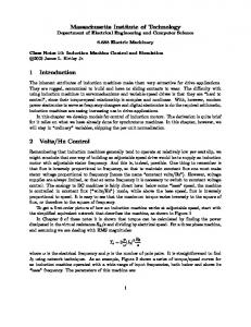
Voltage sags can be either symmetrical or unsymmetrical, depending on the causes. If the individual phase voltages are equal and the phase relationship is 120°, the sag is symmetrical. Otherwise, the sag is unsymmetrical [8]. According to [3] voltage sags can be grouped into seven types, denoted as A, B, C, 0, E, F and G. Table II shows their expressions (where h is the sag depth) and Fig. 1 shows their phasor diagrams. The most common causes of voltage sags are faults, large transformer energizing and large motor starting.
Type B
v
v = hV
- G
- G = hV
J3
~b
=-
I - hV - j-hV
~b
=-
I - hV + j-hV
2
2
J3
2
2
~b
I
2
J3
J3 h V
1 =- - V+ j -
2
v =V
In order to simulate the behaviour of SM, in this paper it has been considered that the sag shape is rectangular, no phase jump occurs and the sag type does not change when the fault is cleared. Hence, the voltage sags will be defined by their depth h (0.1 S h S 0.9), their duration St, and their initial point-onwave lfli [8]. IV. VOLTAGE SAGS EF FECTS
The most relevant voltage sags effects on the SM behaviour are speed variations, with possible loss of the synchronism, current and torque peaks. The machine behaviour is different when symmetrical and unsymmetrical sags are produced in the network. When symmetrical sag is applied to the SM the most severe peaks occur at the beginning and at the end of the sags. Fig. 2 shows the transient effects caused by symmetrical sag on the
730
~b =
./3
~b
=-
1 - hV - j - V
~b
=-
- hV + j - V
2
2
I
./3
2
2
Type F
-G
~b =
2
v = hV
Type E
Fig. I. Voltage sags types: Symmetrical (type A) and unsymmetrical (type B - G). All sags have a depth of 50%. (Obtain ed from [4])
J3 V
=- - V+ j -
-G
=- - V- j - h V 2 2
2
I
~b
TypeD
v = hV
~b
J3
=- - V- j - V 2 2
Type C
-G
I
~b
J3
v
- G
= hV
I --hV - j-hV
2
2
J3
I --hV + j-hV 2 2 Type G
v
-G
=
.!..(2 + h)V 3
~b -~ (2 + h)V - j ~ hV =
~b -~(2 + h)V + j ~ hV =
Where: h
= 0.1 ... 0.9 sag depth
/./3 phase-to-ground
V = UD
ac voltage
A.
Depth Influence
The behaviour of the machine is affected by the sag depth. A sudden drop in the voltage suppl y produces a current peak at beginning of sag and another peak current when the fault is cleared and the voltage is restored. After reaching the first peak value, an oscillation is produced with constant frequency (of the grid) and decreasing amplitude. Both current peaks are more severe if the sag is deeper. For all depths analyzed, the same behaviour is observed. Torque and active power have the same behaviour. rimo/1OCOOdJ
400 0 ".~ .Q
".~
0
200 ,
a
';:;..m -200
-400
a
Fig. 3. Depth influence: 835MVA SM torque against a symmetrical voltage sag: type A, h = 0.1 to 0.9 , /),./ = lOOms(6 cycles), '/1,= 15°
\
V 0.05
0.1
0.15
Time [seconds]
, ::~
.~ '~ .:»
-100 -200
a
0.05
0.1
0.15
0.2
0.25
Time [seconds]
_hi"/
:,r' E . : a
0.05
0.1
0.15
0.2
0.25
0.2
0.25
Time [seconds]
~~I
a
E
0.05
0.1
0.15
Time [seconds]
nm./_0tIdJ
FigA. Depth influence : 5kVA SM torque against a symmetrical voltage sag : typeA,h =O.1 to 0.9,/),./= lOOms, '/1,= 15°
B. Initial point-on-wave influence
I
Fig. 2. 5kVA Synchronous Machine behaviour for a symmetrical voltage sag : type A, h = OA, /),./ = lOOms, '/I' = 15°
Fig. 3 shows torque of hydro turbine generator against symmetrical voltage sag whose depth range is from 10% to 90%. Sag duration is fixed on lOOms (six cycles) for all simulations done and the initial-paint-wave is 15°. It is clear as the impact on torque is more severe if the sag is deeper. The steam turbine generator has a very similar behaviour. Nevertheless, as far as 5kYA machine is concerned, current, torque and active power oscillations are attenuated by winding dampers, as shown in Fig. 4, whose simulations have been made setting the sag duration on lOOms and the initial painton-wave on 15°. Both figures are the result of recursive simulations under specific conditions mentioned above in order to analyze each factor separately.
Initial point-an-wave is also important in the study of the sag effects. Consequently, different fault angles cause different effects on the behaviour of the SM . Fig. 5 show the torque peaks versus the initial point-one-wave on the steam turbine SM for sags types A, B, C, D, E and F. For all simulations, depth sag is 10% and duration sag is three cycles. The current peaks have a very similar behaviour. As can be deduced from this figure, the worst peaks occur near the initial-point-wave of 90 degree for the sags type B, D and F, and for the sags type C and E the most unfavourable peaks are around 0 degrees. In addition, figures show that if the sag is symmetrical (type A), the initial point-an-wave has not influence on the power and torque peaks. Both the current and torque highest values are obtained when sag duration is half a period plus any number of full periods (At = TI2 + kT where k is a integer k = 0, 1,2... ). Hence, the most severe current and torque peaks are produced by the specific initial point-an-wave and sag duration of Table III.
731
TABL E III MOST UN FAVORABLE SA G D URAnON AND INITIAL POI NT-ON- WAVE FOR SY NCHRONOUS M ACHINE
Sag type A C,E B,D,F
lJli
0° 90°
T/2+kT T/2+kT T/2+kT
20
40
60
80
100
120
140
160
180
140
160
180
impact on currents stator is more severe if the sag is longer, when the voltage is restored. Figs. 6 and 7 shows the transient of the angle J obtained of recursive simulations keeping depth sag on 10% and initial point-on wave on 15 degrees.
il=== : .~ point-an-wave [derree]
o
20
40
60
80
100
120
point-an-wave [derree]
! l~===2- r1 o
20
40
60
80
100
120
140
160
180
Time{'ocond/
point-an-wave [derree]
!
T====: •=:=1 o
20
40
60
80
100
120
140
160
Fig. 6. Duration influence: 325MVA SM