Modeling and Validation Processes of an Electric. Vehicle with Statistical Energy Analysis. Artun Bötke. Hexagon Studio, Kocaeli, Turkey. Emin Erensoy.
Modeling and Validation Processes of an Electric Vehicle with Statistical Energy Analysis Artun Bötke Hexagon Studio, Kocaeli, Turkey.
Emin Erensoy Hexagon Studio, Kocaeli, Turkey.
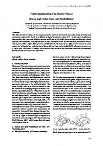
Caner Sevginer Hexagon Studio, Kocaeli, Turkey. Summary The importance of vibroacoustic studies have been increasing consistently in the automotive industry in recent decades. CAE (Computer Aided Engineering) tools are required in these studies to be involved in engineering process of early R&D (Research & Development) stages. To be able to guide the design, full vehicle model and analyses are to be performed confidently from vibroacoustics point of view. FEA (Finite Element Analysis), the most traditional CAE tool in the industry, fails to give confident results in mid and high frequency bands. Therefore, a novel CAE tool called SEA (Statistical Energy Analysis) has been used to overcome this incapability of FEA and analyze vehicles accurately. Engine noise is not dominant in the electric vehicles as in ICE (Internal Combustion Engine) vehicles. Consequently road noise and wind noise, which contain random excitations, have become the main contributors of vehicle interior noise. The randomness of these noise sources increases considered frequency bandwidths and these sources can be radiated from any location of the vehicle. Therefore, controlling acoustic package of the vehicle has become primary issue for electric vehicle NVH development. This paper outlines an overview of virtual model building, analyzing, testing and validation processes of acoustic package of the electrical vehicle, V1 Concept, to emphasize the increasing importance of performing SEA in these situations.
1.
Introduction
Investigation on sound and vibration has been expanded due to the increased popularity of passenger comfort issue. As well as other important issues, quieter and more comfortable vehicles are required. When this demand meets with increased computer technology and competition in automotive market, usage of CAE tools has increased participating of automotive engineers in early stages of vehicle R&D processes. The most extensively used CAE tool is FEA which serves multiple engineering disciplines. However, FEA is incapable of satisfying all aspects of noise and vibration issues. First of all, it does not take into account of viscoelastic losses by solving acoustic equations linearly. This assumption causes increasing error margins in mid and high frequency bands. Secondly, nonlinear acoustic parameters, which are very important for determining acoustic performance of vehicle sound
package, cannot be included [1]. Lastly, FEA needs detailed geometric models which make modeling expensive and difficult in preliminary stages. Consequently, a different CAE method is necessary to overcome limitations of FEA. SEA is the engineering approach which uses energy equations to simulate sound transfer in vehicles. Another advantage of this new CAE method is its convenience for electric vehicles, which create a new challenge in NVH characteristic of the vehicles as they have very low engine noise. On contrary, the most dominant noise is engine noise in ICE (Internal Combustion Engine) vehicles. In these vehicles, engine makes such a high noise that it masks road and wind noises, especially in low speeds. However, due to the fact that electric engine makes lower noise than IC engines; road noise, wind noise and other noises like S&R (squeak and rattle) become prominent [2, 3]. Another crucial point is while engine noise has a fixed excitation in frequency domain, sound
sources like wind noise and road noise have random excitations. Therefore, investigation over much wider frequency bands is necessary, especially in mid and high ones. Furthermore, since the location of engine is definite, sound insulation around engine compartment has become much more important in ICE vehicles. But in electric vehicles, location of the source is totally indefinite because of its randomness [4]. Therefore whole vehicle and whole sound insulation package have to be analyzed which increases modeling size and running time of the model in a traditional CAE tool. Due to these reasons, using SEA in investigating inner acoustic package is one of the most significant studies in the electric vehicles. In this paper, the authors summarize modeling and analyzing a vehicle with SEA, testing in various scenarios and validation process of the model with tests in the aspect of being an electric vehicle. Afterwards, reasons of error margins in validation have been also investigated to understand the method, its application style and have a technical background for possible future studies.
2.
Model Building
In this study, an electrical and right-hand drive taxi version of Concept V1, shown in Figure 1, was investigated. To model and analyze the vehicle virtually, VA One, SEA product of ESI, is used as engineering software.
modeling factors regarding SEA such as keeping plate subsystems as big as possible [5, 6, 7, 8, 9]. Secondly, 3D CAD model of the vehicle was imported into an FEA software to create coarse nodes and elements. This FE model then was imported into VA One and SEA plate subsystems were created considering the modeling strategy. Inner and outer cavity subsystems were also created in relation with these subsystems. In Figure 2, all SEA subsystems can be seen.
Figure 2. SEA subsystems of the vehicle
As a final step to build SEA model of the vehicle, material samples were collected and sent to a material laboratory to obtain their acoustic material parameters, such as porosity, tortuosity and damping loss factor. These parameters were assigned to each material in the virtual model. However, samples from all materials could not be obtained due to subcontractor problems, which lead considerable error margins in the results.
3.
Tests and Analyses
Physical tests were also conducted to form boundary conditions for analyses and validate the virtual model. Tests were performed in two different conditions to ensure the validation and understand NVH behavior of an electric vehicle.
Figure 1. Concept V1.
First of all, a modeling strategy, specific for Concept V1, has been formed. There are several parameters which lead to this strategy: Unique glazed roof structure of Concept V1, being an electric vehicle, test scenarios, extensity of inner space, a division of inner space by a partition and
First condition is a controlled environment. In a semi-anechoic chamber, a constant spherical sound source between 100-10000 Hz was placed in front and rear regions of each tire by two different output nozzle; a simple nozzle, which behaves as if it is a point sound source, and a tire patch. The sound source was identified as the boundary condition in analyses. Measurements, taken at rear and driver seats with an artificial head, were used as results. Second condition is the track, a closed traffic outer environment. In this track, the vehicle is driven at three constant speeds; 10 kph, 20 kph and 40 kph.
Measurements, performed at tires and engine compartment, applied as boundary conditions or noise sources. Measurements, performed at the rear seat with an artificial head and driver seat with a microphone, identified the receiver points.
Result graphs for test with a simple nozzle at semi-anechoic chamber
Figure 3. Nozzle placement examples at test in semianechoic chamber.
Figure 6. Rear region of front right tire to left ear of rear passenger.
Figure 4. Tire patch placement example at test in semianechoic chamber.
Figure 5. Test at the track and the artificial head in rear seat of the vehicle.
Figure 7. Rear region of front left tire to left ear of rear passenger.
Sound pressure levels [dB(A)], obtained from measurements as stated previously, were transformed into sound energy levels (W) with a linear equation (Eq. 1) [10] and these values were injected in related cavities in the virtual model.
(1)
4. Results As there are lots of load cases and result graphs, only one result graph is shown for each condition.
Figure 8. Front region of rear right tire to left ear of rear passenger.
Figure 9. Front region of rear left tire to right ear of rear passenger.
Figure 12. Front region of rear right tire to left ear of rear passenger.
Result graphs for test with a tire patch at semianechoic chamber
Figure 13. Front region of rear left tire to right ear of rear passenger. Figure 10. Rear region of front right tire to right ear of driver.
Result graphs for test at the track
Figure 14. Response at right ear of driver @10 kph. Figure 11. Rear region of front left tire to left ear of driver.
parameters were used instead of real parameters in these materials [12]. This situation is the main contributor of error margins.
Figure 15. Response at right ear of driver @20 kph.
• In a vehicle, door/window weather-strips and seals are two of the main contributors in sound transmittance. In an ideal SEA model, weather-strips and strips should be modeled separately and a special test should be conducted to obtain their „acoustic transmittance coefficients‟. Because this need came out towards the end of modeling process and there were budget and organization limitations, weather-strips and seals could not be modeled. Only „slit‟ was defined at related subsystems to minimize the error. • SEA is a very user dependent method [11]. User‟s experience affects directly accuracy of model and modeling speed. User dependent errors were tried to be minimized by communicating with an experienced engineer in ESI constantly during whole modeling process.
Figure 16. Response at right ear of driver @40 kph.
5.
Discussion
Error margins, up to 10 dB, are seen in the result graphs. Causes of these margins can be divided into two main categories; dependent and independent causes from the method. Former category causes ±3 dB error margin and its factors are: • It is accepted that there is linear connection between SEA subsystems. However, acoustic material parameters are nonlinear. To avoid this situation, acoustic material parameters should be obtained for all trim materials and assigned in virtual model [11]. • Equipartition of energy means that each mode exhibits equal energy, which gives an upper bound to response [9]. • Inner and outer air is divided into subsystems. It is accepted that each subsystem has equal energy level inside and has different energy level from adjacent subsystems [8]. Second category includes error reasons which are independent from the computation: • As said previously, samples of some materials could not be obtained. So generic
• Leakage points of the prototype could not be modeled in CAE tools completely. Therefore, test results could be disagreed from results of the analyses. Although electric vehicles give the opportunity to eliminate ICE related noise sources and reduce the noise emissions; other noise sources, road surface – tire interaction noise (road noise), wind noise and S&R (squeak & rattle) issues, still remain. Therefore, interior sound evaluations should be performed according to these aspects in higher and wider frequency bandwidths than ICE vehicles. Engine presence also covers most of the accessories noise in ICE vehicles. However, electric motor could not cover these kinds of accessories‟ noise due to its noise level. During tests, accessories like steering pumps, which are normally not identified during ICE vehicle drive, observed. Then, these new NVH conditions will be studied in further development stage of Concept V1.
6.
Conclusion
In this study, an electric vehicle, Concept V1, has been modeled and analyzed by SEA method. In the meantime, physical NVH tests have been conducted on the prototype vehicle. Results of analyses and tests have been compared to validate SEA model and understand NVH behavior of an electric vehicle.
Error margins up to 10 dB have been seen between result values of analyses and test measurements. Causes of these errors have been investigated thoroughly. Difference of NVH behavior of a vehicle due to having an electric engine, instead of ICE, has also been discussed. Further acoustic pack studies will also be carried out as the next step.
Acknowledgement The authors are grateful to Hexagon Studio for supporting this work. The authors also wish to apologize for the unintentional exclusions of missing references and would appreciate receiving comments and pointers to other relevant literature for a future update. The presented study was carried out in the context of the research project “Determination of Sound Isolation Package of an Electric Vehicle with Statistical Energy Analysis (Bir Elektrikli Araç Ses İzolasyon Paketinin İstatistiksel Enerji Analiziyle Tespiti)” and funded by National Support Programs (1501 - Tübitak Sanayi Ar-Ge Projeleri Destekleme Programı). The authors would like to graciously thank everyone who contributed to this work; in particular Dr. Joe Venor (ESI) for his generously technical support, Şener Yılmaz for his efforts in early stages of the work, Deniz Yazgaç for his theoretical support, Onur Öztürk and M. Murat Ergeldi (Onatus) for their support, Bahar Korkmaz and Nilay Yalçınkaya Yörük for their procedural and organization support.
References [1] C. Wang, S. Oh, Q. Zhang, K. Schneider: An Efficient Modeling Approach for Mid-frequency Trim Effects. SAE Technical Paper 2011-01-1719 (2011) doi:10.4271/2011-01-1719. [2] G. Eisele, K. Wolff, M. Wittler, R. Abtahi et al.: Acoustics of Hybrid Vehicles. SAE Technical Paper 2010-01-1402 (2010) doi:10.4271/2010-011402. [3] N. Otto, R. Simpson, J. Wiederhold: Electric Vehicle Sound Quality. SAE Technical Paper 1999-01-1694 (1999) doi:10.4271/1999-01-1694. [4] H. Van der Auweraer, K. Janssens: A SourceTransfer-Receiver Approach to NVH Engineering of Hybrid/Electric Vehicles. SAE Technical Paper 2012-36-0646 (2012) doi:10.4271/2012-36-0646.
[5] A. Charpentier, D. Blanchet, K. Fukui: Full Vehicle SEA Model Uses Detailed Sound Package Definition To Predict Driver's Headspace Acoustic Response. Proc. Inter-noise 2004, 22-25 August 2004, Prague, Czech Republic. [6] A. Charpentier, C. Birkett, M. Sánchez, V. Dias: Modeling Airborne Noise Transmission in a Truck using Statistical Energy Analysis: SAE Technical Paper 2007-01-2432 (2007) doi:10.4271/2007-012432. [7] L. Zhang, D. Blanchet: Modeling VibroAcoustical Behavior of Cockpit Module Using Statistical Energy Analysis (SEA) Method. Proc. Inter-noise 2002, 19-21 August 2002, Dearborn, USA. [8] J. Venor, A. Müller, S. Nintzel: SEA Modeling and Validation of Structure and Airborne Interior Noise in Automobiles. Proc. Vibro-Acoustic Users Conference, 29-30 January 2003, Leuven, Belgium. [9] J. Venor: Advanced SEA Training Course: Automotive. ESI Group (2010). [10] H.N. Özgüven: Gürültü Kontrolü: Endüstriyel ve Çevresel Gürültü. TMMOB Makina Mühendisleri Odası, Ankara, 1986. (Reprinted by Türk Akustik Derneği 2008). [11] J. Plunt, C. Fredö, M. Sanderson: On the Use and Misuse of Statistical Energy Analysis for Vehicle Noise Control. SAE Technical Paper 931301 (1993) doi:10.4271/931301. [12] M. Bijarimi, H. Zulkafli, M.D.H. Beg: Mechanical Properties of Industrial Tyre Rubber Compounds. Journal of Applied Sciences (2010) 1345-1348.