HARMONIC analysis is a major issue of power quality as- sessment. With the widespread ... AC electric arc furnace (EAF) is another example that has nonlinear ...
1802
IEEE TRANSACTIONS ON POWER DELIVERY, VOL. 19, NO. 4, OCTOBER 2004
Modeling Devices With Nonlinear Voltage-Current Characteristics for Harmonic Studies Task Force on Harmonics Modeling and Simulation
Abstract—This paper documents the modeling of harmonic sources with nonlinear voltage-current characteristics such as transformers, iron-core reactors, rotating machines, arc furnaces, energy efficient lightings, and some household electronic appliances. The harmonic generating characteristics of these apparatus are reviewed. Different modeling techniques are summarized and suggestions for the use of different models are also provided whenever possible. Index Terms—Electric arc furnaces (EAFs), electronic ballast, harmonics, magnetic core, saturation.
I. INTRODUCTION
H
ARMONIC analysis is a major issue of power quality assessment. With the widespread use of power electronics equipment and nonlinear loads, industrial, public and household equipment/appliances, the understanding and modeling of harmonic sources have been an essential part of harmonic analysis. The fundamental causes of power system harmonics can be categorized as follows: a) Device nonlinearity. This includes such devices as magnetic core reactors, transformers and induction motors, due to the saturation behavior of their magnetic elements. AC electric arc furnace (EAF) is another example that has nonlinear resistance variations due to the ionized gas (plasma). b) Non-sinusoidal flux distribution in the stator of electric machines. c) Periodic switching of power electronic equipment used in the generation, transmission, distribution and utilization levels of power systems. Certain types of harmonics-generating equipment and load may fall into two or more of these categories. For instance, DC-EAF’s and fluorescent lights utilizing a power electronic converter combine the periodic switching of the power converter with the nonlinear characteristic of their dc load. Among the third category of harmonic sources, power electronic converters play a significant role in generating harmonics. The harmonic characteristics and modeling of power electronic converters has been documented in an earlier paper by this task force for different converter types assuming a linear dc load or
Manuscript received February 5, 2003; revised June 3, 2003. Paper no. TPWRD-00049-2003. Task Force on Harmonics Modeling and Simulation is with the Harmonics Working Group, IEEE PES T&D Committee. G. Chang (chair), C. Hatziadoniu (vice chair), W. Xu (past chair), P. Ribeiro (past vice chair), R. Burch, W. M. Grady, M. Halpin, Y. Liu, S. Ranade, D. Ruthman, N. Watson, T. Ortmeyer, J. Wikston, A. Medina, A. Testa, R. Gardinier, V. Dinavahi, F. Acram and P. Lehn. Digital Object Identifier 10.1109/TPWRD.2004.835429
dc link for the converter. In harmonic analysis programs, these devices constitute linear harmonic sources. This includes linecommutated converters based on the six-pulse thyristor bridge and forced commutated converters based on the voltage-source inverter. This paper focuses on the modeling of harmonic sources with nonlinear voltage-current characteristics. In harmonic analysis programs, these devices constitute the nonlinear components of the system. Examples include the saturated transformer, the arc furnace, and the over-excited induction motor. Most commonly used models include, but are not limited to, current source model, harmonic impedance model, and equivalent circuit model with voltage-dependent components. II. NONLINEAR MAGNETIC CORE SOURCES A. Iron-Core Reactors and Transformers Transformers are one of the most prevalent components in power systems. The saturation effects of transformers and ironcore reactors can be major sources of power system harmonics. 1) Harmonic Origins and Characteristics: Harmonics are generated from the magnetic core saturation, which begins when the core flux enters the nonlinear region of the magnetization curve [1]. While some saturation occurs during normal operation, significant over-excitation can lead to excessive harmonic generation. Major line conditions likely to cause transformer significant over-excitation include: a) Temporary over-voltage caused by reactive power unbalance. Temporary over-voltages typically follow load rejection or excessive control action [2]. b) Unbalanced transformer load. This can cause uneven distribution of the magnetizing current among the transformer phases. Load unbalance can cause transformer saturation even if the fundamental line voltage is within its normal limits. c) Low frequency magnetizing current can bias the transformer core and cause asymmetric saturation. This can be generated from adjustable speed drive (ASD) loads [3] or through geo-magnetic induction (geo-magnetically induced current, GIC) [4], [5]. d) Transformer energization, especially in over-voltage conditions. The asymmetric core saturation generates a slowly decaying inrush current, which can further cause excessive harmonic over-voltage [6], [7]. Symmetric core saturation generates odd harmonics, while asymmetric core saturation generates both odd and even harmonics. The overall amount of harmonics generated by a transformer depends not only on the saturation level of the magnetic
0885-8977/04$20.00 © 2004 IEEE
TASK FORCE ON HARMONICS MODELING AND SIMULATION: MODELING DEVICES
1803
TABLE I DUALITY BETWEEN MAGNETIC AND ELECTRIC CIRCUITS
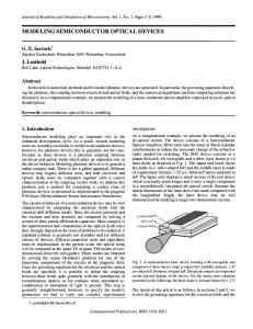
The equations describe the relationships between winding voltages, winding currents, winding resistance, winding turns, magneto-motive forces, mutual fluxes, leakage fluxes, and reluctances. Saturation, hysteresis, and eddy current effects can be well modeled. Numerical algorithms are used to solve the equations. The models are suitable for transient studies such as inrush or fault related simulations. They may also be used to simulate the harmonic generation behavior of power transformers. Among these models, the one represented in a matrix form of (1) is of special interest. This model is the framework of transformer models for many electromagnetic transient programs Fig. 1. (a) Single phase transformer equivalent circuit. (b) Flux linkage/current relationship for the nonlinear magnetizing inductance.
core, but also on the structure and configuration of the transformer. Several harmonic models can be used to represent a transformer. Commonly seen models are the equivalent model, the differential equation model, and the duality-based model. 2) Equivalent Circuit Model of Core Saturation: In harmonic studies where it is necessary to model transformers as harmonic sources, the first step is to model saturation of the main flux path in the core. For single- phase transformers in particular, this is often sufficient for the study. In time domain studies, the equivalent circuit of Fig. 1 can be used to model a single-phase transformer in per unit quantities. The core saturation is modeled using a piecewise linear approximation of saturation, as shown in Fig. 1(b). An approximation of this plot can be derived from the transformer ac saturation curve. This model is increasingly available in time domain circuit simulation packages. Detailed discussions of transformer nonlinear core modeling can be found in [3], [8]–[16], [21], [70]. Three phase banks wound on a single core will often require more detailed magnetic circuit modeling, for both shell form and core form banks [21]–[26]. This is particularly true for the zero sequence harmonics. In these cases, a duality based model is generally used to capture the various flux paths of the transformer. Many harmonic studies are done in the frequency domain rather than in the time domain. [17]–[20] develop the harmonic space representation of transformers. This method involves Norton equivalents for the transformer core at each harmonic frequency. An iterative harmonic analysis is employed, which converges to the flux linkage-current relationship of the core. 3) Differential Equation Model: These models represent a transformer as a set of differential equations [13], [17]–[20].
.. .
.. .
.. .
..
.. .
.. .
.
.. .
..
.. .
.
.. .
.. .
(1)
In (1), N is the number of transformer terminals, denotes the voltage of terminal i, denotes the current flowing into terminal i, and denote the resistance and inductance between terminals i and j, respectively [13]. Saturation effects are modeled by connecting the piecewise nonlinear inductance across the winding closest to the core [21]. 4) Duality-Based Model: Duality-based models are necessary to represent multi-legged transformers because a simple T model cannot represent accurately their complex core topology. The equivalent circuit of such a model can be derived from the duality between magnetic and electric circuits (Table I) [12], [22]–[26]. Its parameters may be derived from experiment data and a nonlinear inductance may be used to model the core saturation. Duality-based models are suitable for simulation of power system low-frequency transients such as inrush currents, ferroresonance, short circuits, and abnormalities including transformer winding faults. They can also be used to study the harmonic generation behaviors. 5) GIC Saturation Model: The geomagnetically induced currents (GIC) are currents flowing in the power transformers grounded neutrals as a result of the potential difference between geological regions caused by solar magnetic disturbance. For a
1804
IEEE TRANSACTIONS ON POWER DELIVERY, VOL. 19, NO. 4, OCTOBER 2004
and are the direct and quadrature sub-transient where inductance, respectively [30], [31]. A more complex model is represented by the following impedance [8]: (2)
Fig. 2. A GIC saturation model.
transformer under severe GIC bias that causes heavy half cycle saturation, it becomes necessary to account for the flux paths in and between core, tank and air gaps. A detailed model based on 3D finite element calculation may be necessary [4]. Fig. 2 gives the equivalent magnetic circuit model of a single-phase shell-type transformer. An iterative program can be used to solve the circuitry so that nonlinearity of the circuitry components is considered. The piecewise harmonic balance method [5] can be used to solve the nonlinear time domain circuit and the frequency dependent linear circuit iteratively. 6) Summary of Transformer Modeling: Core saturation is the major harmonic modeling concern for transformers. There are two general rules to apply. For time domain solutions, model the saturation as a nonlinear inductance connecting the winding closest to the core. For frequency domain solutions, one could replace the nonlinear inductance with voltage dependent current sources [14]. B. Rotating Machines Synchronous machines and induction motors have different harmonic characteristics and modeling considerations. 1) Synchronous Machines: Harmonics of synchronous machines have several origins: a) Non-sinusoidal flux distribution. The resulting voltage harmonics are odd and usually minimized in the machine’s design stage [27]. Its contribution is often negligible in the models. b) Frequency conversion process. This refers to the harmonic generation behavior of a synchronous machine under unbalanced conditions [28], [29]. The unbalance causes a negative sequence current in the stator. This current may induce a 2nd harmonic current in the rotor. That current may induce a 3rd harmonic current back into the stator, due to saliency effects. A similar phenomenon occurs at harmonic frequencies [89] and produces interactions beharmonic flows. This effect can become tween h and particularly apparent in salient pole machines which are in the vicinity of HVDC terminals. c) Saturation Harmonics. Saturation occurs in the stator and rotor core, and in the stator and rotor teeth. In large generators, these are often negligible [89]. For balanced (single phase) harmonic analysis, a synchronous machine was often represented by a single approximation of at each harmonic order , inductance
where is in the range of 0.5 to 1.5 (accounting for skin efand are the negative fect and eddy current losses), sequence resistance and reactance at fundamental frequency, respectively. The above models are not valid for unbalanced three-phase networks. For harmonic load flow analysis, especially when machines operate asymmetrically, more complex models should be used. Among the available models the three-phase coupled matrix model is the most popular one, which is defined as (3) , , and where are zero and negative sequence impedance at hth harmonic order, respectively. Note that this model is of a balanced synchronous machine. If the synchronous machine stator is not precisely balanced, the self and/or mutual impedance will be unequal. Besides, [28] derived a three-phase complex admittance matrix model that considered the frequency conversion process. Reference [29] developed a frequency-dependent three-phase equivalent circuit model that counted not only the frequency conversion process and the saturation effects, but also the machine’s load flow constraints. These models are useful for analyzing specialized operating conditions where the harmonics from the machine are of primary concern. 2) Induction Motors: Induction motor could be a source of harmonic generating in the following aspects: 1) Stator winding configuration. Due to the fact that windings are not continuously distributed at the stator, the resulting magnetomative force (MMF) will not be a continuous sinusoid with applied sinusoid stator voltage. However, this problem is minimized in the machine’s design stage. Its contribution is often neglected in the models. 2) Transients. When the induction motor just starts up from stall or the load is changing, both the stator current and rotor current will vary at high frequency to adapt the changing state of the motor. Therefore, some harmonics will exist in the starting currents. The above-mentioned phenomenon can generally be neglected—the primary contribution of induction motors is to act as an impedance to harmonic excitation. In this section, we discuss different models of induction motors under harmonic and/or unbalanced condition. At the fundamental frequency, it is well known that the model of induction motors involves more parameters than that of synchronous machines, therefore it is expected that the reactions of the induction motor to harmonic voltages and currents are more complex than that of a synchronous machine. The modeling of an induction motor can be very complex. For system harmonic analysis, detailed modeling is rarely of necessity. The motor is either modeled as
TASK FORCE ON HARMONICS MODELING AND SIMULATION: MODELING DEVICES
Fig. 3. Double cage model for induction motors (the rotor impedances were modified with ‘(s)’).
1805
Fig. 5. Zero sequence equivalent circuit of induction motors [35].
It is known that for a perfectly balanced system: [33] are purely pos• Harmonicsof order itive-sequence are purely • Harmonics of order negative-sequence are purely zero-se• Triplens quence For an unbalanced system, any harmonics may be partially made up of any of the sequences. For example, for an unbalanced 5th harmonics, if we arbitrarily select the magnitude of phase A, B, and C as 2, 3, and 5, respectively, and assume that the fundamental phases are 120 apart. The symmetrical components can be calculated as the following:
Fig. 4. Equivalent T model for induction motors.
impedance for balanced systems, or as a three-phase coupled matrix for unbalanced systems. The balanced equivalent impedance can be derived from any of the following five equivalent models. a) Generalized Double Cage Model Fig. 3 shows the equivalent circuit at the fundamental and represent the resistance and power frequency. represents the magneleakage reactance of the stator. represents core losses. represents tizing reactance. the mutual reactance of the two rotor cages. , , and represent the slip-dependent resistance and reactance of the two rotor cages (For single cage induction ). motor, At the harmonic order, the equivalent circuit can be obtained by multiplying with each of the reactance in Fig. 3. b) Equivalent T Model Fig. 4 shows the model for the -order of harmonic frequency. This is the modification of the well-known induction motor model, where is defined as
(4) where is the full load slip at fundamental frequency, and is the harmonic order. Negative sign is taken for positive sequence models, and positive sign is taken for negative sequence models. Circuit parameters in Fig. 4 are to be obtained using the standard motor test procedure [32].
The above-mentioned slip dependence of harmonic order models, in section (b), would need to modify to include the positive, negative and zero sequence circuits if the input source is unbalanced. c For unbalanced system harmonic analysis, the three-phase coupled matrix is in the form of (3), but now , , where and are the zero and positive sequence impedance, respectively. can be determined from the model. can be determined from the zero sequence equivalent circuit [35], as shown in Fig. 5. 3) Suggestions for Machine Modeling: When selecting machine models, it is important that complex models require more input parameters that may not be available and require extra computational resources, while the solution accuracy may not always be better than that of using simple models. For instance, all of the aforementioned induction motor models are good for harmonic analysis but yield similar results. If one sticks to the most complex model, one may get into more trouble than necessary. Analyze the problem and the software tools in use and make a compromise toward the simple model. III. ARC FURNACE HARMONIC SOURCES Because the harmonics generated by a DC arc furnace are mostly determined by its AC/DC converter and the character-
1806
IEEE TRANSACTIONS ON POWER DELIVERY, VOL. 19, NO. 4, OCTOBER 2004
B. Arc Furnace Models
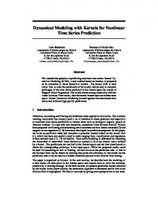
Fig. 6. A typical AC arc furnace system.
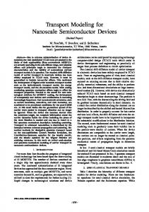
Fig. 7. Arc furnace characteristics: (a) V-I characteristic of furnace arc. (b) Theoretical AC current waveform of furnace.
istic is more predictable, most models described in this section focuses on AC arc furnaces. A. Characteristics of Harmonics Generated by Arc Furnaces Electric arc furnaces (EAF) are commonly encountered in steel plants. Due to the uncontrolled nature of the steel melting process, current harmonics generated by arc furnaces are unpredictable and random. Fig. 6 depicts a typical arc furnace system supplied by an ac is small. The substasource [36]. The source impedance tion transformer HV/MV connects the high voltage bus to the medium voltage bus. The furnace transformer MV/LV connects the medium voltage bus to the arc furnace electrodes. There may be other loads connected to the two buses. The arc furnace load and . impedance includes the series of Due to current chopping and igniting in each half cycle of the supply voltage, arc furnaces generate a wide range of harmonic frequencies. Fig. 7(a) shows the typical hysterics characteristic of the furnace arc and Fig. 7(b) shows the resulting arc current and voltage when a sinusoidal source supplies the furnace [37], [38]. Typical spectrum of arc furnace currents is shown in Fig. 8 [39]. It can be seen that besides integer harmonics, the arc furnace currents are also rich in inter-harmonics. One of the utility concerns of arc furnace applications is the low power factor. To increase the power factor of an arc furnace, Static Var Compensator (SVC) systems or filters are usually installed near the arc furnace. The SVC or filters could reduce the 3rd, 5th and higher order harmonics but will also generate side band or pole frequencies [40]. In some cases, resonance conditions appear near one of the integer harmonic frequencies, causing harmonic voltages in the network. Therefore, the filter must be carefully designed to ensure that no resonance frequency exist near one of the low order integer harmonic frequencies. This may involve frequency scan analysis of the system using an admittance matrix solution technique or an ElectroMagnetic Transient Program (EMTP) simulation [41].
Although an arc furnace can be modeled simply as an inductor in series with a resistor [8], many complex models were proposed to more precisely represent its characteristics and to study its impacts on power systems. 1) Nonlinear Resistance Model: When the arc V-I curve shown in Fig. 7(a) is simplified to that of Fig. 9, the arc furnace can be represented as the equivalent circuit in Fig. 10, where R1 is a positive resistor, R2 is a negative resistor, and the AC clamper is a current-controlled switch. This model has been used in Transient Network Analyzer (TNA) simulations [42]. It is a primitive model and does not consider the time-varying characteristic of arc furnaces. 2) Current Source Models: Typically, an EAF is modeled as a current source for harmonic studies. The source current can be represented by its Fourier series [43]
(7) where the Fourier coefficients may change randomly during every period. The coefficients can be selected as a function of the following items: a) The harmonics of practical arc furnace currents; b) The probability distributions of the current harmonics; c) The proportion of the reactive power fluctuations to the active power fluctuations; d) The measured arc furnace current data from the field. This model can be used to size filter components and evaluate the voltage distortions resulting from the harmonic current injected into the system. Reference [44] proposes another model that is based on chaos theory. The model can generate data from identified parameters. It can be used for arc furnace installation planning or impact studying of installed arc furnaces. 3) Voltage Source Models: The voltage source model for arc furnaces is a Thevenin equivalent circuit. The equivalent impedance is the furnace load impedance (including the electrodes). The voltage source is modeled in different ways. One way is to form it by major harmonic components that are known empirically. One example of such harmonic component ratios to the fundamental component is shown in Table II [37]. This method may lose the stochastic characteristics of arc furnaces, like the nonlinear resistance model does. A more proper way is to account for the stochastic characteristics of the arc furnace and model the voltage source as square waves with modulated amplitude. A new value for the voltage amplitude is generated after every zero-crossings of the arc current when the arc must restrike. Several methods have been proposed to generate the amplitude value for each half cycle of the arc current [39], [45], [46]. 4) Nonlinear Time Varying Voltage Source Model: This model is actually a voltage source model [47], [48]. The arc voltage is defined as a function of the arc length (8) (8)
TASK FORCE ON HARMONICS MODELING AND SIMULATION: MODELING DEVICES
Fig. 8.
1807
Typical spectrum of arc furnace currents [38].
Then, we may define
(11) where is the real arc length, be written as
,
.
can
(12) Fig. 9.
Simplified V-I curve of arc furnaces.
from which (8) can be obtained. The time variation of the arc length is modeled with deterministic or stochastic laws. The deterministic law is usually a sinusoidal law, which provides the worst-case approximation (13)
Fig. 10.
is the maximum variation of arc length, and is an where angular frequency in the range of 0.5 to 25 Hz, which is the popular flicker frequency range of an arc furnace. The stochastic law defines a white-noise time variation
Nonlinear resistance model.
TABLE II TYPICAL VOLTAGE HARMONIC COMPONENTS FURNACES
FOR
SCRAP
AND
(14)
LADLE
where is the arc voltage corresponding to the reference arc is responsible for arc length time varilength , and where ations. Assume that the V-I curve of the arc furnace has the form of
where is a band-limited white noise. Its frequency band is in the range of the flicker frequency of the arc furnace. Both the deterministic and stochastic laws can be applied to a balanced and an unbalanced arc furnace. 5) Nonlinear Time Varying Resistance Models: Furnace operation can be described by three basic states: open circuit, short circuit and normal operation. During normal operation, the arc resistance can be modeled to follow an approximate Gaussian distribution. Random fluctuation in arc resistance is given by [45] (15)
(9) where is the threshold value, C and D are constants determined by the conditions of arc firing and extinction
where is the variance, is the mean resistance, and is de. termined by short-term perceptibility flicker index For a DC arc furnace, the arc resistance can be modeled as randomly varying at a periodical manner [23] (16)
(10)
where RAND uniformly distributes in [0,1].
1808
Fig. 11.
IEEE TRANSACTIONS ON POWER DELIVERY, VOL. 19, NO. 4, OCTOBER 2004
A time varying resistance arc furnace model [38].
A recently proposed time varying resistance model relates the (positive resistance) and reference arc furnace resistance (negative resistance) to the short-term power consumed by the arc furnace [38] (17) and are arc ignition and extinction voltages, rewhere spectively. The model is shown in Fig. 11. The static model depends only on and V-I characteristics of the arc furnace. The dynamic model has time variations. In case of a sinusoidal variation (18) In case of band limited white noise variation (19) where BLW is the band-limited white noise. 6) Frequency Domain Models: In frequency domain, the arc furnace is modeled as parallel harmonic current sources. [36] proposed a three-phase arc furnace model in the frequency domain for steady state iterative harmonic analysis (IHA). The model describes the arc furnace in two operation modes: the discontinuous operation mode and the continuous operation mode. Harmonic currents corresponding to the two modes are (20)
and (21) where and are harmonic orders, is the rms harmonic phasor of the current, is the rms harmonic phasor of the , , , are voltage ( denotes the conjugate), is the threshold arc voltage. admittances, and 7) Power Balance Models: The power balance model describes the arc furnace with a differential equation [80], [81] (22)
where is the arc radius; exponent is selected according to the , 1, or 2; recommended values arc cooling environment, are 0, 1 and 2; , and are constants for exponent (Typical values of , and can be found in [80]). In [80], the arc furnace model is represented in the frequency domain whereas in [81] the representation is in the time domain. Newton techniques can be used for the fast computation of the periodic steady-state solution [82]. 8) Summary of Arc Furnace Models: Nonlinear resistance model and major harmonic voltage source model are simple but cannot represent the stochastic characteristic of an arc furnace. Current source model and amplitude modulated voltage source model can simulate the arc furnace statistically correct. Nonlinear time varying models and power balance models are new ways of arc furnace modeling. Frequency domain model is more suitable for steady state iterative harmonic analysis.
IV. OTHER NONLINEAR VOLTAGE-CURRENT HARMONIC SOURCES A. Energy Efficient Lights Harmonics of gas discharge and fluorescent energy efficient lights (EEL) result from their nonlinear V-I characteristic and the action of their ballast. Their V-I curve is similar to that of Fig. 7, which produces mostly triplen harmonics, especially the 3rd [49]. Their ballast is categorized into two major types: the electromagnetic ballast and the electronic ballast. Early electronic ballasts often had higher current THD’s than the magnetic ballasts that they were replacing. Recent well designed electronic ballasts, however, have addressed this issue, and the low order harmonic currents are at or below those exhibited by magnetic ballasts. Electronic ballasts do, however, exhibit high frequency switching effects which can lead to conducted or radiated interference. On the other hand, a magnetically ballasted EEL always has lower efficiency than an electronically ballasted EEL. The current harmonics of a magnetically ballasted EEL are mostly of odd orders with the 3rd being the dominant [50]. The total harmonic distortion (THD) of the current (% of fundamental) ranges from around 10% to over 30% [50]–[56], sometimes can be as high as 160%. Due to the large amount of electronic ballast types, the harmonic contents of an electronically ballasted EEL vary dramatically. In general, these harmonics are of all orders with even harmonics being of small amplitude. Again, 3rd harmonic is the dominant [57]. Electronically ballasted EEL’s with high harmonic distortion may have a THD as high as over 100% up to 140% [51], [54], [58]. Well designed electronic ballasts, i.e. those with good performance passive or active filtering technologies, can reduce the THD of an EEL to below 30% [54], [55], [58], [59], sometimes as low as 10% [52], [58]. A capacitor is sometimes connected in parallel with an EEL to increase its power factor, which can worsen the THD [53], [60], [61], sometimes up to 50% [61]. An electronically ballasted EEL is often simply modeled as parallel harmonic current sources with known magnitude and
TASK FORCE ON HARMONICS MODELING AND SIMULATION: MODELING DEVICES
1809
where Pph is the per phase corona power loss, and Uph is the phase voltage. The later depends on the weather conditions, the design of the overhead lines, and the ratio between the equivalent electric field intensity on the surface of the wires and the initial intensity at which general corona appears in good weather [69]. Overhead transmission line corona harmonic source can be modeled by means of distributed nonlinear shunt resistors. Reference [70] gives an example of the resistor representations
TABLE III HARMONIC SOURCE PARAMETERS OF AN EEL MODEL
phase angle [51], [62]. One example of these parameters is shown in Table III [54]. For an electro-magnetically ballasted EEL, the modeling objects include both the lamp tube and the electro-magnetic ballast. The V-I characteristics of the lamp may be approximated using [83] (23) or [84] (24)
(28) is the peak voltage, is the corona power loss per where phase per kilometer, is the line-to-neutral critical corona represents a nonlinear shunt resistance onset voltage, and per km. The instantaneous corona current per km can be determined by
and t1 is a zero-crossing of the current, where or more accurately, using [85]
(29)
(25)
where is the instantaneous voltage. The nonlinear characteristics cause the possibility of generating current harmonics along such lines. Corona losses vary widely with a number of factors including weather and voltage. [90] provides a cumulative probability function of corona loss measured over a one year period, which shows the loss exceeding 20 kW/km for less than 10% of the time.
and are measured parameters that correlate where and the lamp current , is the average the lamp voltage lamp power which is best measured during high frequency operation. The lamp may also be modeled by means of a cross-frequency harmonic admittance matrix [86]. The overall lamp system including both the electromagnetic ballast and the lamp tube may be modeled using harmonic-domain approach [87]. B. Household Electronic Appliances Household electronic appliance includes PCs, TVs, VCRs, electronic washing machines, microwave ovens, laser printers, etc. They have spiked current waveforms that contain mainly odd harmonics. The dominant harmonics are triplens. The 5th and 7th harmonics also have high amplitude [64]–[67]. Their current THD may be as high as 140% [65], [66], [68]. A statistical summation method of calculating the harmonic current is proposed in [88]. Like an EEL, a household electronic appliance can be modeled as parallel harmonic current sources with known amplitude and phase angle. C. Coronas Corona on high-voltage overhead transmission lines is an important source of third harmonic current pollution under unfavorable conditions. The resulted ratio of third harmonic corona current to fundamental corona current could be in the range of 0.2 to 0.3 [69]. The third harmonic corona current can be estimated using the following equation: (27)
V. CONCLUSIONS The harmonic generation characteristics and modeling methods of harmonic sources with nonlinear voltage-current characteristics are reviewed. For iron core reactors and transformers, magnetic nonlinearity as well as core topology and peripheral circuit must be considered. The model for synchronous machines is simple, but it could be more involved for induction machines. Because of the stochastic nature of arc furnace operation, the harmonic models for arc furnace are diverse. For other nonlinear harmonic sources such as energy efficient lights, household electronic appliances and corona, readers may refer to the references provided for more detailed information. ACKNOWLEDGMENT The Task Force would like to acknowledge the following authors for their major contributions: Z. Wang (editor), S. Tsai (editor), T. Ortmeyer (editor), Y. Liu (editor), W. Xu (editor), G. Chang (editor and Chair), V. Dinavahi, C. Hatziadoniu, A. Medina, R. Natarajan, N. Watson, and P. Ribeiro. REFERENCES [1] Y. Liu and Z. Wang, Modeling of harmonic sources—magnetic core saturation, in IEEE Tutorial on Harmonic Modeling, IEEE 1998 WM and SM, ch. 5.
1810
[2] CIGRE Working Group 33.10 and IEEE Task Force on Temporary Overvoltages, “Temporary overvoltages: causes, effects and evaluation,” in Proc. CIGRE Int. Conf. Large High Voltage Electric Systems, vol. 2, 1990, paper 33-210. [3] Z. Wang and Y. Liu, “Harmonic analysis of transformers under converter load with DC and low frequency bias,” in Proc. American Power Conf., vol. 59, pp. 449–454. [4] S. Lu, Y. Liu, and J. De La Ree, “Harmonics generated from a DC biased transformer,” IEEE Trans. Power Delivery, vol. 8, pp. 725–731, Apr. 1993. [5] S. Lu and Y. Liu, “Harmonics from DC biased three-phase transformer banks,” Int. J. Power Energy Syst., vol. 17, no. 1, 1997. [6] J. J. LaForset, Transmission Line Reference Book, 345 kV and Above, EPRI EL-2500, 2nd ed., Palo Alto, CA, 1982. [7] A. Greenwood, Electrical Transients in Power Systems, 2nd ed. New York: Wiley, 1991. [8] CIGRE Working Group 36-05, “Harmonics, characteristic parameters, methods of study, estimates of existing values in the network,” Electra, no. 77, pp. 35–54, 1981. [9] A. Medina and J. Arrillaga, “Generalized modeling of power transformers in the harmonic domain,” IEEE Trans. Power Delivery, vol. 7, pp. 1458–1465, July 1992. [10] Y. Baghzouz and X. D. Gong, “Voltage-dependent model for teaching transformer core nonlinearity,” IEEE Trans. Power Syst., vol. 8, pp. 746–752, May 1993. [11] J. David and C. A. Gross, “Nonlinear modeling of transformers,” IEEE Trans. Ind. Applicat., vol. 24, pp. 434–438, May 1988. [12] X. Chen and S. S. Venkata, “A three-phase three-winding core-type transformer model for low-frequency transient studies,” IEEE Trans. Power Delivery, vol. 12, pp. 775–782, Apr. 1997. [13] V. Brandwajn, H. W. Dommel, and I. I. Dommel, “Matrix representation of three-phase N-winding transformers for steady-state and transient studies,” IEEE Trans. Power App. Syst., vol. PAS-101, pp. 1369–1378, June 1982. [14] H. W. Dommel, A. Yan, and S. Wei, “Harmonics from transformer saturation,” IEEE Trans. Power Delivery, vol. PWRD-1, pp. 209–215, Apr 1986. [15] A. H. Chowdhury, W. M. Grady, and E. F. Fuchs, An Investigation of the Harmonic Characteristics of Transformer Excitation Current Under Nonsinusoidal Supply Voltage. [16] W. L. A. Neves and H. W. Dommel, On Modeling Iron Core Nonlinearities. [17] A. Semlyen, E. Acha, and J. Arrillaga, “Harmonic Norton equivalent for the magnetizing branch of a transformer,” Proc. Inst. Elect. Eng., vol. 134C, no. 2, pp. 162–169, Mar. 1987. , “Newton-type algorithms for the harmonic phasor analysis of non[18] linear power circuits in periodical steady state with special reference to magnetic nonlinearities,” IEEE Trans. Power Delivery, vol. 3, pp. 1090–1098, July 1988. [19] E. Acha, J. Arrillaga, A. Medina, and A. Semlyen, “General frame of reference for analysis of harmonic distortion in systems with multiple transformer nonlinearities,” Proc. Inst. Elect. Eng., vol. 136C, no. 5, pp. 271–278, Sept. 1989. [20] A. Medina and J. Arrillaga, “Simulation of multilimb power transformers in the harmonic domain,” Proc. Inst. Elect. Eng., vol. 139C, no. 3, pp. 269–276, May 1992. [21] C. G. A. Koreman, “Determination of the magnetizing characteristic of three-phase transformers in field tests,” IEEE Trans. Power Delivery, vol. 4, pp. 1779–1785, Oct. 1989. [22] E. C. Cherry, “The duality between interlinked electric and magnetic circuits and the formation of transformer equivalent circuits,” Proc. Physical Society, pt. B, vol. 62, pp. 101–111, 1949. [23] G. R. Slemon, “Equivalent circuits for transformers and machines including nonlinear effects,” Proc. Inst. Elect. Eng., pt. IV, vol. 100, pp. 129–143, 1953. [24] A. Narang and R. H. Brierley, “Topology based magnetic model for steady-state and transient studies for three-phase core type transformers,” IEEE Trans. Power Syst., vol. 9, pp. 1337–1349, Aug. 1994. [25] C. M. Arturi, “Transient simulation and analysis of a five-limb generator step-up transformer following an out-of-phase synchronization,” IEEE Trans. Power Delivery, vol. 6, pp. 196–207, Jan. 1991. [26] B. A. Mork, “Five-legged wound-core transformer model: derivation, parameters, implementation, and evaluation,” in Proc. IEEE Power Eng. Soc. WM, PE-414-PWRD-0-12-1997. [27] J. Arrillaga, D. A. Bradley, and P. S. Bodger, Power System Harmonics. New York: Wiley, 1985.
IEEE TRANSACTIONS ON POWER DELIVERY, VOL. 19, NO. 4, OCTOBER 2004
[28] A. Semlyen, J. F. Eggleston, and J. Arrillaga, “Admittance matrix model of a synchronous machine for harmonic analysis,” IEEE Trans. Power Syst., vol. PWRS-2, pp. 833–839, Nov. 1987. [29] W. Xu, H. W. Dommel, and J. R. Marti, “A synchronous machine model for three-phase harmonic analysis and EMTP initialization,” IEEE Trans. Power Syst,, vol. 6, pp. 1530–1538, Nov. 1991. [30] W. M. Grady and G. T. Heydt, “Prediction of power system harmonics due to gaseous discharge lightning,” IEEE Trans. Power App. Syst., vol. PAS-104, pp. 554–561, Mar. 1985. [31] T. J. Densem, P. S. Bodger, and J. Arrillaga, “Three phase transmission system modeling for harmonic penetration studies,” IEEE Trans. Power App. Syst., vol. PAS-103, pp. 310–317, Feb. 1984. [32] IEEE Standard Test Procedure for Polyphase Induction Motors and Generators, IEEE Std. 112-1996. [33] R. C. Dugan, M. F. McGranaghan, and H. W. Beaty, Electrical Power Systems Quality. New York: McGraw-Hill, 1996, pp. 172–173. [34] G. J. Rogers and D. Shirmohammadi, “Induction machine modeling for electromagnetic transient program,” IEEE Trans. Energy Conversion, vol. EC-2, pp. 622–628, Dec 1987. [35] J. T. Mitchell, “Equivalent circuits for 3-phase 4-wire induction motors operating on nonsymmetrical systems,” AIEE Trans., pp. 468–476, 1959. [36] J. G. Mayordomo, L. F. Beites, R. Asensi, M. Izzeddine, L. Zabala, and J. Amantegui, “A new frequency domain arc furnace model for iterative harmonic analysis,” IEEE Trans. Power Delivery, vol. PD-12, pp. 1771–1778, Oct. 1997. [37] D. Andrews, M. T. Bishop, and J. F. Witte, “Harmonic measurement, analysis, and power factor correction in a modern steel manufacturing facility,” IEEE Trans. Ind. Applicat., vol. 32, pp. 617–624, May/June 1996. [38] S. Varadan, E. B. Makram, and A. A. Girgis, “A new time domain voltage source model for an arc furnace using EMTP,” IEEE Trans. Power Delivery, vol. PD-11, pp. 1685–1691, July 1996. [39] R. Collantes-Bellido and T. Gomez, “Identification and modeling of a three phase arc furnace for voltage disturbance simulation,” IEEE Trans. Power Delivery, vol. PD-12, pp. 1812–1817, Oct. 1997. [40] B. Bhargava, “Arc furnace flicker measurements and control,” IEEE Trans. Power Delivery, vol. 8, pp. 400–410, Jan. 1993. [41] L. Tang, D. Mueller, D. Hall, M. Samotyj, and J. Randolph, “Analysis of DC arc furnace operation and flicker caused by 187 Hz voltage distortion,” IEEE Trans. Power Delivery, vol. 9, pp. 1098–1107, Apr. 1994. [42] R. C. Dugan, “Simulation of arc furnace power systems,” IEEE Trans. Ind. Applicat., vol. IA-16, pp. 813–818, Nov./Dec. 1980. [43] M. D. Cox and A. Mirbod, “A new static VAR compensator for an arc furnace,” IEEE Trans. Power Syst., vol. PWRS-1, pp. 110–120, Aug. 1986. [44] E. O’Neill-Carrillo, G. T. Heydt, E. J. Kostelich, S. S. Venkata, and A. Sundaram, “Nonlinear deterministic modeling of highly varying loads,” in Proc. IEEE Power Eng. Soc. SM 174, 1998. [45] H. M. Peterson, R. G. Koch, P. H. Swart, and R. van Heerden, “Modeling arc furnace flicker and investigating compensation techniques,” in Proc. IEEE Ind. Applicat. Soc. Annu. Meeting, vol. 2, 1995, pp. 1733–1740. [46] D. Stade, H. Schan, and S. Kramer, “Modeling of the electrical behavior of arc furnace,” in Proc. 29th Universities Power Engineering Conf., vol. 1, Sept. 1994, pp. 125–128. [47] G. C. Montanari, M. Loggini, A. Cavallini, and L. Pitti, “Flicker and distortion compensation in electrical plant supplying arc-furnaces,” in Proc. IEEE Ind. Applicat. Soc. Annu. Meeting, vol. 3, 1994, pp. 2249–2255. [48] G. C. Montanari, M. Loggini, A. Cavallini, L. Pitti, and D. Zaninelli, “Arc-furnace model for the study of flicker compensation in electrical networks,” IEEE Trans. Power Delivery, vol. PD-9, pp. 2026–2033, Oct. 1994. [49] W. B. Lawrence, G. Michalik, W. Mielczarski, and J. Szczepanik, “Reduction of harmonic pollution in distribution networks,” in Proc. 1995 Int. Conf. Energy Management Power Delivery, vol. 1, pp. 198–202. [50] Y. N. Chang, C. S. Moo, and J. C. Teng, “Harmonic analysis of fluorescent lamps with electromagnetic ballasts,” in Proc. IEEE Region 10 Conf. Computer, Communication, Control Power Engineering, vol. 5, 1993, pp. 499–502. [51] D. J. Pileggi, E. M. Gulachenski, C. E. Root, T. T. Gentile, and A. E. Emanuel, “The effect of modern compact fluorescent lights on voltage distortion,” IEEE Trans. Power Delivery, vol. 8, pp. 1451–1459, July 1993. [52] E. E. Santander, A. Domijan Jr., and C. W. Williams Jr., “A comprehensive harmonic study of electronic ballasts and their effect on a utility’s 12 kV, 10 MVA feeder,” IEEE Trans. Power Delivery, vol. 10, pp. 1591–1599, July 1995.
TASK FORCE ON HARMONICS MODELING AND SIMULATION: MODELING DEVICES
[53] A.-C. Liew, “Excessive neutral currents in three-phase fluorescent lighting circuits,” IEEE Trans. Ind. Applicat., vol. IA-25, pp. 776–782, July/Aug. 1989. [54] R. Dwyer, A. K. Khan, R. K. McCluskey, and R. Sung, “Evaluation of harmonic impacts from compact fluorescent lights on distribution systems,” IEEE Trans. Power Syst., vol. 10, pp. 1772–1788, Nov. 1995. [55] C. Sanharan, “Effects of harmonics on power systems—part 3,” Elect. Construction Maintenance, vol. 96, Mar. 1997. [56] L. M. Tolbert, H. D. Hollis, and P. S. Hale Jr., “Survey of harmonics measurements in electrical distribution systems,” in Proc. IEEE Ind. Applicat. Soc. Annu. Meeting, vol. 4, 1996, pp. 2333–2339. [57] C. M. Fu and M. T. Chen, “The characteristics of fluorescent lamps under problematic utility voltage,” in Proc. Int. Conf. Energy Management Power Delivery, vol. 1, 1995, pp. 140–145. [58] R. R. Verderber, O. C. Morse, and W. R. Alling, “Harmonics from compact fluorescent lamps,” IEEE Trans. Ind. Applicat., vol. IA-29, pp. 670–674, May/June 1993. [59] A. M. Luciano, M. Savastano, and F. Avallone, “Characterization of a new device for fluorescent lamps supplying,” in Proc. IEEE Instrum. Measurement Technology Conf., vol. 3, 1994, pp. 1179–1182. [60] D. Braun, L. Rodnunsky, M. Steen, and D. Koval, “Harmonic and electrical characteristics of fluorescent ballasts,” in Proc. Canadian Conf. Electrical and Computer Engineering, vol. 2, 1996, pp. 667–670. [61] S. Rios, R. Castaneda, and D. Veas, “Harmonic distortion and power factor assessment in city street gas discharge lamps,” IEEE Trans. Power Delivery, vol. 11, pp. 1013–1020, Apr. 1996. [62] E. Gluskin, “High harmonic currents in fluorescent lamp circuits,” IEEE Trans. Ind. Applicat., vol. 26, pp. 347–351, Mar./Apr. 1990. [63] E. F. EI-Saadany and M. M. A. Salama, “Reduction of the net harmonic current produced by single-phase nonlinear loads due to attenuation and diversity effects,” Int. J. Electr. Power Energy Syst., vol. 20, pp. 259–268, May 1998. [64] T. M. Gruzs, “A survey of neutral currents in three-phase computer power systems,” in Proc. Rec. Ind. Commercial Power Systems Technical Conf., 1989, pp. 114–122. [65] K. Sachs, R. W. Larson, D. P. Decoster, and S. Plato, “A low-impedance uninterruptible power technology for nonlinear critical loads,” in Proc. IEEE 1986 IAS Annual Meeting, vol. 2, pp. 1036–1042. [66] P. J. A. Ling and C. J. Eldridge, “Designing modern electrical systems with transformers that inherently reduce harmonic distortion in a PC-rich environment,” in Proc. Int. Power Quality Telecomputer Infrastructure Conf., 1994, pp. 166–178. [67] D. O. Koval and C. Carter, “Power quality characteristics of computer loads,” in Proc. IEEE Ind. Applicat. Soc. Annu. Meeting, vol. 3, 1995, pp. 2265–2272. [68] A. E. Emauel, J. Janczak, D. J. Pileggi, E. M. Gulachenski, C. E. Root, M. Breen, and T. J. Gentile, “Voltage distortion in distribution feeders with nonlinear loads,” IEEE Trans. Power Delivery, vol. 9, pp. 79–87, Jan. 1994. [69] E. Yu, Y. Zmaznov, S. Kraichik, V. T. Minin, and A. S. Sokhranskii, Corona on wires of high-voltage lines as a source of the third current harmonic in electrical networks, in Thermal and Mechanical, pp. 64–69, 1989. [70] M. M. Saied and E. A. Qufi, “An assessment of the harmonic pollution due to line corona,” Elect. Mach. Power Syst., vol. 12, no. 1, pp. 127–139, 1993. [71] S. Calabro, F. Coppadoro, and S. Crepaz, “The measurement of the magnetization characteristics of large power transformers and reactors through D.C. excitation,” IEEE Trans. Power Delivery, vol. PWRD-1, pp. 224–234, Oct. 1986.
1811
[72] G. R. Slemon and E. A. Ismailov, “An analysis of the harmonic impedance of a saturated induction machine,” IEEE Trans. Power App. Syst., vol. PAS-99, pp. 1663–1669, July/Aug. 1980. [73] A. C. Smith, “Harmonic field analysis for slip-ring motors including general motor asymmetry,” in Proc. IEEE Ind. Applicat. Soc. Annu. Meeting, vol. 1, 1989, pp. 31–37. [74] D. Zaninelli and P. Zanotti, “Simplified frequency-dependent model for induction machines,” Elect. Mach. Power Syst., vol. 22, no. 6, pp. 727–752, 1994. [75] A. Semlyen, E. Acha, and J. Arrillaga, “Harmonic Norton equivalent for the magnetizing branch of a transformer,” Proc. Inst. Elect. Eng., vol. 134C, no. 2, pp. 162–169, Mar. 1987. [76] , “Newton-type algorithms for the harmonic phasor analysis of nonlinear power circuits in periodical steady state with special reference to magnetic nonlinearities,” IEEE Trans. Power Delivery, vol. 3, pp. 1090–1098, July 1988. [77] E. Acha, J. Arrillaga, A. Medina, and A. Semlyen, “General frame of reference for analysis of harmonic distortion in systems with multiple transformer nonlinearities,” Proc. Inst. Elect. Eng., vol. 136C, no. 5, pp. 271–278, Sept. 1989. [78] A. Medina and J. Arrillaga, “Simulation of multilimb power transformers in the harmonic domain,” Proc. Inst. Elect. Eng., vol. 139C, no. 3, pp. 269–276, May 1992. [79] B. C. Smith, J. Arrillaga, A. R. Wood, and N. R. Waston, “A review of iterative harmonic analysis for ac-dc power systems,” in Proc. IEEE Conf. Harmonics Quality of Power , Las Vegas, NV, Oct. 1996, pp. 314–319. [80] E. Acha, A. Semlyen, and N. Rajakovic, “A harmonic domain computational package for nonlinear problems and its applications to electric arcs,” IEEE Trans. Power Delivery, vol. 5, pp. 1390–1397, July 1990. [81] A. Medina and N. García, “Newton methods for the fast computation of the periodic steady state solution of systems with nonlinear and timevarying components,” in Proc. Conf. IEEE Power Eng. Soc. Summer Meeting, vol. 2, Edmonton, AB, Canada, July 18–22, 1999, pp. 664–669. [82] A. Semlyen and A. Medina, “Computation of the periodic steady state in systems with nonlinear components using a hybrid time and frequency domain methodology,” IEEE Trans. Power Syst., vol. 10, pp. 1498–1504, Aug. 1995. [83] E. Gluskin, “On the theory of fluorescent lamp circuits,” Proc. Inst. Elect. Eng., Sci., Meas. Technol., vol. 137, no. 4, pp. 201–208, July 1990. , “Discussion of the voltage/current characteristics of a fluorescent [84] lamp,” Proc. Inst. Elect. Eng., Sci., Meas. Technol., vol. 136, no. 5, pp. 229–232, Sept. 1989. [85] U. Mader and P. Horn, “A dynamic model for the electrical characteristics of fluorescent lamps,” in Proc. IEEE Ind. Applicat. Soc. Annu. Meeting, vol. 2, 1992, pp. 1928–1934. [86] M. Fauri, “Harmonic modeling of nonlinear load by means of crossed frequency admittance matrix,” IEEE Trans. Power Syst., vol. 12, pp. 1632–1638, Nov. 1997. [87] G. W. Chang, S. K. Chen, and G. Chen, “Harmonic-domain modeling of fluorescent lamp with electromagnetic ballast,” in Proc. IEEE Summer Meeting, 2001. [88] F. Gorgette, J. Lachaume, and W. M. Grady, “Statistical summation of harmonic currents produced by a large number of single phase variable speed air conditioners: a study of three specific design,” IEEE Trans. Power Delivery, vol. 15, pp. 953–959, July 2000. [89] N. Dinh and J. Arrillaga, “A salient-pole generator model for harmonic analysis,” IEEE Trans. Power Syst., vol. 16, pp. 609–615, Nov. 2001. [90] K. Lahti, M. Lahtinen, and K. Nousiainen, “Transmission line corona losses under hoar frost conditions,” IEEE Trans. Power Delivery, vol. 12, pp. 928–933, Apr. 1997.