Modeling Enterprise Information and Enabling Access using Information Sharing Server R. Karinthi*, V. Jagannathan, V. Montan, J. Petro, M. Sobolewski, R. Raman, G. Trapp*, Stephen Deng, G. Almasi, Xi Li
The address of all the above authors is: Concurrent Engineering Research Center Drawer 2000, P.O. Box 6506, West Virginia University Morgantown, WV 26506 Primary contact person: Raghu Karinthi email:
[email protected] phone: (304)293-7226.
* Also with the Department of Statistics and Computer Science, West Virginia University To be presented at the ASME Engineering Database Symposium in International Computers in Engineering Conference, San Diego, August 1993 ACKNOWLEDGEMENT: This effort has been sponsored by Defense Advance Research Projects Agency (DARPA), under contract No. MDA972-91-J-1022 for DARPA Initiative in Concurrent Engineering (DICE).
1
ABSTRACT The engineering data of a large enterprise is typically distributed over a wide area and archived in a variety of databases and file systems. Access to such information is crucial to a team member, particularly in a concurrent engineering setting. However, this is not easy, because (1) a model of the relevant information is not available, and (2) there is no simple way to access the information without being knowledgeable about various computer data formats, file systems, and networks. However, in a concurrent engineering environment, there is every need to be aware of the perspectives of the other members of the team. We have developed a system called the Information Sharing Server (ISS) to enable access to diverse and distributed information within a corporation. Such data could be stored in different repositories such as databases (relational, object oriented, etc.) and file systems including those that contain multiple media (text, graphics, audio, etc.).The ISS maintains an enterprise model that is visible to the user. The modeling of the enterprise is done in a language called EXPRESS developed by the STEP consortium as an international standard. The ISS also stores mappings from the model to the actual data residing in the repositories. The ISS accepts requests from the user and converts them into requests specific to a repository. The request is then communicated to the repository over the network and the results are fetched back to the user. The ISS is currently integrated with engineering data of two domains: electrical and mechanical. Our paper describes the methodology of the ISS, the details of the implementation and extensions planned for the future. We believe the transparency offered by the ISS will make it a very useful tool for an engineer and make it very convenient to integrate heterogeneous legacy databases. I
INTRODUCTION
Managing engineering data is becoming an increasingly complex task. Heterogeneity of hardware and software platforms is one of the barriers to be overcome in achieving this end. With increasing use of computers, we have islands of automation that have resulted in information archival in databases, file systems and such. This makes the access to information easy for someone who uses a single repository as their primary or native environment. However, the information access problem increases manyfold when one wishes to access enterprise-wide information. Access to enterprise-wide information is very important in a collaborative setting when a number of people access a corpus of information, albeit with different perspectives. A major problem to be addressed is how to integrate all the information, how to deal with legacy systems and how to provide a single view to the user abstracting all the hardware and software specifics of the individual systems. The Information Sharing System (ISS) we describe in this paper, enables access to heterogeneous information over a wide area with special emphasis on multimedia nature of future repositories. This includes all the CAD drawings and other kinds of raster and vector data, in addition voice and video clips that will be archived in the future. This system is generic and can be used in a variety of applications. We have prototyped the use of our system in several scenarios, including product development in mechanical engineering and electronics settings. The need for accessing information by people viewing from different perspectives arises in a concurrent engineering setting. One way of promoting concurrent engineering is through what is called the tiger team. A tiger team is composed of members from multiple disciplines, each of whom provide a unique perspective in a product development environment. Unconstrained by arbitrary barriers, the members of a tiger team communicate their insights, make recommendations, 2
and negotiate conflicts. In so doing, they bring problems to light early. This results in better quality products developed in a shorter time with reduced cost. However, in a number of organizations, physically collocating a team of relevant experts is very difficult or even impossible. For a variety of reasons, the relevant people, their tools and computer equipment are located in geographically dispersed locations, and the cost involved in collocating the people and the appropriate tools may be too high. The concept of a virtual team was developed at the Concurrent Engineering Research Center (CERC) and in the DARPA Initiative in Concurrent Engineering (DICE). A virtual team is much like a traditional tiger team except that the team members can be geographically dispersed. In order for them to function effectively, they are connected via a computer network. A computer model of the enterprise, or at least the product being developed, is provided so that each individual can get a global picture of the organization (or product) and how he/she fits in as a part of the whole. Such a model will enable cooperative work among the team members by enabling information sharing and monitoring the progress of product development. This means that all the heterogeneous repositories used by the team members are well integrated. This is the motivation for our work in integrating heterogenous engineering data repositories. The paper is organized as follows: Section II describes the methodology of the ISS and related approaches. Section III gives an overview of the ISS system. Section IV describes the architecture in detail. In Section V, we describe the multimedia repository and the multimedia gateway of the ISS. Section VI describes the relational database gateway of the ISS. In Section VII, we describe one of the scenarios we have developed to illustrate the functionality of the ISS. Section VIII describes the mapping methodology we have employed. Section IX provides some notes on the implementation along with some of the implementation decisions made. In Section X, we describe the Graphical User Interface of the ISS. Section XI describes the current status of the system and Section XII outlines our plans for the future. Section XIII summarizes our efforts on the ISS project. II
METHODOLOGY
The Information Sharing System provides a model-directed view of the overall information. This information model is central to the ISS philosophy. Such a model is conceptual and is not (necessarily) identical to the schema of any of the information repositories in the enterprise. Examples of such a model are that of a turbine blade, an electronic printed circuit board and a VLSI chip manufacture process. The approach we are using is to develop an information model and to integrate specific repositories with the model. Our approach is described in greater detail in subsequent sections. In the context of integrating multiple databases and information repositories, several other approaches have been suggested. The federated (see Heimbigner and McLeod ,1985; Navathe et al, 1989, and Seth and Larson, 1990)) or multidatabase (see Litwin, Mark and Roussopoulos, 1990) approaches avoid constructing a global schema and present the user with a collection of local schemas along with tools for information sharing among the databases. In this case, the user integrates only the necessary portions of the databases. There are several advantages to this approach such as increased security, easier maintenance, and the ability to deal with inconsistent databases. We believe that such an approach is suitable when the different databases in the federation contain similar data, but not when a wide variety of information repositories (not all of which are data3
bases) need to be integrated. In such cases, the user needs to be guided through the information available via a model. The Carnot project (Collet, Huhns and Shen, 1991) at MCC uses an approach that is different from ours as well as the federated scheme. Carnot has a large body of knowledge or ontology that is available from the Cyc knowledge base (see Lenat and Guha, 1990; and Guha and Lenat, 1990). Cyc, being a knowledge-based system, has a rich representational structure. The bulk of the knowledge in Cyc is common sense facts about the world (such as how tall humans are) and does not include enterprise-specific information. Such information is added to Cyc, thus expanding Cyc’s ontology. The Carnot project is also aimed at integrating multiple databases. There are systems that are geared to serving multimedia information alone. Examples of this are the object-oriented database management system - OMEGA (Masunaga, 1991), multimedia object presentation manager in MINOS (Christodoulakis, Ho, and Theodoridou, 1986), and the multimedia office server - MULTOS (Meghini, Rabitti and Thanos, 1991). All these systems have several features in common with the multimedia capabilities of the ISS. However, they do not address the problems of integrating heterogeneous information and wide-area information access. In order to build an enterprise model we felt that the object oriented paradigm was best-suited to capture both the hierarchical nature of enterprises as well as their behaviors. For the purpose of modeling, we chose the data modeling language EXPRESS (1991), designed as part of the STEP international standard. EXPRESS was chosen primarily because it is a data definition language and it is an upcoming international standard. It may be noted here that the EXPRESS language currently does not provide methods, and hence we are not planning to incorporate methods into our current model. The EXPRESS models are subsequently converted to C++ using translators. III
SYSTEM OVERVIEW
Figure 1 shows the schematic of a system called the Information Sharing System (ISS). The goal of the Information Sharing System is to provide the means for a user to transparently access information over a wide area. Since much of the information already exists in a variety of computer information repositories such as databases, documents, drawings, and data files, it is imperative that the ISS be integrated with these existing repositories. For this reason, there cannot be one shrink-wrapped solution that can be deployed in a variety of enterprises with little or no customization. Keeping this in mind, we designed the ISS to provide the user with a system that is integrated with representative information repositories along with methodologies that enable the implementation in a phased manner. Earlier prototypes to this include the Knowledge Server (Bell Atlantic Software Systems, 1991) and the PPO Server efforts carried out in earlier phases of the DICE project.
4
DBA ISS
MIND
GATEWAYS
API
Client UI
RDB
MMR
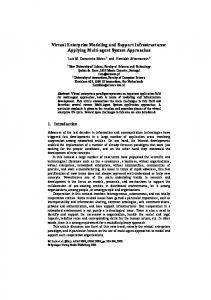
Application ISS: Information Sharing System API:Application Programmers Interface MIND:Model-based INformation Directory DBA:Database Administrator RDB:Relational Database MMR:Multi-Media Repository Figure 1: Overview of the Information Sharing System Central to the ISS is a module called the Model-based Information Directory (MIND). The MIND contains a model of the information which is distributed in various repositories. The ISS provides access to the model to enable a user to view how the information is organized. The user can navigate through all the information using the model. The MIND also maintains a mapping from the model to the actual information in each of the repositories. Using the mapping, the ISS can assist a user in accessing the information which has been modeled. The ISS has been integrated with a commercial Relational Database Management Systems (RDBMS) viz., ORACLE, and a commercial Object-Oriented Database Management Systems (OODBMS) viz.,VERSANT. In our examples, the OODBMS manages the data which point to multimedia files. IV
System Architecture
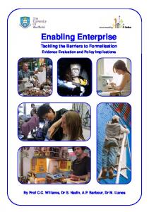
With the above overview of the system, we now examine the detailed architecture of the ISS depicted in Figure 2. In the figure, the arrows indicate the flow of data. The data flow is in response to a request for information in the other direction. DBA Modeler 5
DBA Modeler
EXPRESS Importer
DBA Data Editor
Database Administrator Tools Modelbased Information Directory database
MIND
Access Manager
Client Application
Repository Manager
Model Manager
Map Manager
Query Processor
Communications Module
Relational Database Gateway
Multi-media Repository Gateway
ORACLE RDBMS
Multi-media Document Repository
Data Flow
Figure2: Architecture of the Information Sharing System The DBA Modeler is a stand-alone tool which can be invoked by the database administrator for the purpose of interactively creating, modifying, deleting, and viewing the classes that comprise the information model in the Model-based Information Directory. Each class defined in the model is an entity specification, which in turn represents information stored in one or more data repositories. The classes are specified in C++ and are stored in persistent form using the VERSANT objectoriented database management system. DBA Data Editor The DBA Data Editor is another stand-alone tool which can be invoked by the Database Administrator for the purpose of interactively creating, modifying, deleting, and viewing the instances of the user access information and the mapping information in the Model-based Information Directory. The DBA editor allows one to create information identifying individual users and their access privileges. It also allows one to create the mapping information which correlates model components with the repositories wherein the actual data resides. Repository-specific information, such as name, type, and communications parameters (internet addresses, port numbers), are created 6
using the DBA editor. A conceptual Repository class and instances are stored in persistent form via the VERSANT object-oriented database management system. EXPRESS Importer The EXPRESS Importer is another stand-alone tool which can be invoked by the Database Administrator for the purpose of incorporating a file containing EXPRESS language definitions of one or more classes into the Model-based Information Directory. The class definitions are converted from EXPRESS into C++ by means of a VERSANT-supplied translation utility, and then stored in the MIND database. As before, each class defined in the model signifies an enterprise model entity specification which represents information stored in one or more data repositories. MIND The Model-based Information Directory (MIND) process is the VERSANT object-oriented database management system server that provides access to the database containing the model information. It provides a communications interface via which client applications, such as the ISS Server process, may access the database. Access Manager The Access Manager contains the methods for authenticating a user’s requests. Users can login to the system, provide a password and obtain identifiers from ISS. Transactions are validated by verifying the authorization information (access identifiers) against the access information managed in the MIND. Model Manager The Model Manager is a module that performs a set of services related to the model. These services include identifying the existence of a class in the model; identifying the attributes, unique attributes, and relationships of a given class, as well as their data type; and retrieving the definition of a specific class. The class definitions are created by the DBA Modeler tools or EXPRESS Importer tools and are stored in the MIND database. Map Manager The Map Manager is a module that performs a set of services related to the information in persistent storage that pertains to enterprise model-to-repository mappings. The mappings themselves are created by the DBA Data Editor tool and are stored in a VERSANT database. Section VIII gives a more detailed description of the Map Manager. Client Application The Client Application/User Interface assists a user in examining the information model using a user-friendly graphical interface built with Motif. It also assists the user in browsing the data in the enterprise, retrieving the data, and searching for data. Section X gives a more detailed description of the graphical user interface. Repository Manager The Repository Manager module processes incoming requests made by a client application. It controls the operations of the ISS, ensuring transaction validation and routing of the request to the model manager or the query processor as appropriate. 7
Query Processor The Query Processor is responsible for interpreting an enterprise query, which is based on the enterprise model, and for forming the individual queries for each of the repositories. The query presented to the Query Processor through the Communications Module which is formulated based on the information model. For this purpose, we have developed a simple query language similar to SQL. This language has the functionality of a subset of SQL. In this language, we try to select instances or attribute value pairs in which certain conditions hold. The query will be a request for information which may reside in external repositories, which can be an external relational database, an external multi-media repository or any repository for which a gateway has been built. The Map Manager enables the Query Processor to determine where each piece of the requested information is located and how it may be extracted. The Query Processor then formulates the necessary queries and submits them via the Communications Module to the appropriate repository gateways. The Query Processor then consolidates the results from the repository gateways to form the result of the original query. Communications Module The Communications module provides inter-process communications and supports the transfer of requests and results between the client application programs and the ISS Server process, and also between the ISS Server process and the RDB and MMR Gateway processes. It contains methods for packing and unpacking the various requests and results into the format for transfer over the communications media. The communications module uses Unix sockets for transporting packets and NIH class (Gorlen, Orlow, and Plexico, 1990) mechanisms for reading and writing objects to and from persistent storage. RDB Gateway The Relational Database (RDB) Gateway is a separate process which accepts queries from the ISS Server process, converts them to the format specific to the relational database management system with which it is associated, and submits the transformed queries to the DBMS employing ORACLE’s Application Programming Interface (API). ORACLE has an embedded SQL facility that allows SQL queries to be included in C programs. The results of the queries are obtained from the DBMS, packaged, and then transferred back to the ISS Server. Section VI gives a more detailed description of the RDB Gateway. Multi-media Gateway The Multi-media Repository (MMR) Gateway is a separate process which accepts queries from the ISS Server process, converts them to the format specific to the multi-media repository system with which it is associated, and submits the transformed queries to the MMR, utilizing its API. The results of the queries obtained from the MMR, which are either document files or information about documents, are packaged and then transferred back to the ISS Server. Section V gives a more detailed description of the MMR Gateway. V
Multimedia Repository and the MMR Gateway
In the process of implementing ISS, we also implemented a multimedia repository based on the VERSANT OODBMS. In this section, we will describe the details of the multimedia repository, the multimedia gateway and the communication of the gateway with the server process. When 8
the ISS server receives a query request from the user, it decomposes the query and sends it to the appropriate gateway. At the time the ISS is configured, the internet address of the machines and the port numbers on which the gateways are listening is known, and the message is sent to the appropriate port in the appropriate machine across the network. MMR-ISS Gateway The MMR-ISS Gateway is the interface between the MMR and the ISS. The MMR-ISS Gateway gets the inputs from the ISS Query Processor and passes the inputs to MMR Query Handler in VERSANT Object SQL format. When the MMR Gateway gets the answer from the MMR Query Handler, the MMR Gateway sends the answer back to the ISS. The internal query sent by ISS server uses a SQL-like format we have chosen for the query language. A condition can have relational operators on the attributes and a query can have a conjunct of conditions. MMR Query Handler The MMR Query Handler takes inputs from the MMR Gateway and connects to the desired database(s) and then sends the request to VERSANT Object SQL interface to find answers in the object-oriented databases. After the search is completed, the MMR Query Handler returns the answer(s) back to the MMR Gateway. If the answer from MMR Query Handler is related to multimedia objects, then the MMR Gateway is also responsible for packing all related multimedia objects which are related to the answer. This is explained below. The result of a query can be of a simple type, such as integer, string, and float or it can be a multimedia file. If the result is a multimedia file, then the attributes of the file such as the type, owner, name, and a pointer to the contents are stored in VERSANT as a single object. These attributes are used to retrieve the actual file, which is sent back to the ISS server. The ISS Graphical User Interface presents the file in the appropriate form to the user. Currently, we can handle any file type as long as it has an appropriate application to display it. Our environment has Framemaker files, audio files, and a variety of graphical file formats (GIF, TIFF, JPEG, etc.). OSQL Interface The OSQL interface provides users or applications with a SQL like database management language interface to manipulate information in the database. An OSQL statement can be made to the OSQL interface either from a shell or from an application. The OSQL statement is sent to VERSANT using an interface called ‘vt’. MMRepository All the multimedia information is stored as files. Currently, we support Framemaker files with hyperlinks, audio files, and a variety of graphical formats. The files are stored and managed by the Unix file system. The information about a multimedia file such as its type, creation date, name, and pathname are stored and managed by the VERSANT OODBMS. Thus, the file object stored in VERSANT database is the handle for retrieving the file itself. VI
The RDB Gateway
The RDB Gateway works in a similar manner to the MMR Gateway described in the previous section. The RDB-ISS Gateway gets input from the ISS Query Processor and sends the query to the RDB Query Handler. The RDB Query Handler reformats the ISS Query into a format suitable 9
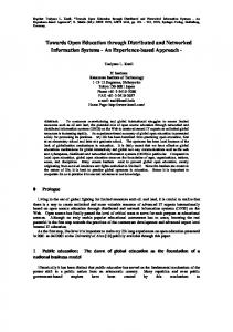
for Oracle. Oracle has embedded SQL facility and a PRO*C interface that enable SQL statements to be embedded in C language programs. Using this interface we can query Oracle and obtain the results back. After obtaining the results to the query, the RDB Query Handler gets the information from Oracle such as the type, size, and number of rows. All of these results are sent back to the ISS server to be presented to the user. VII The Coffee Cup Scenario We will illustrate ISS with a toy scenario of a (hot) coffee cup manufacturing company. Even though the scenario is fictitious, several of the databases that are used are elaborate systems built in other projects. Figure 3 depicts the four databases involved in the hotcup scenario. The first database resides on VERSANT and contains the linking data, which contains the ‘glue’ information that supports the model and integrates the remaining databases. It is explicitly built as part of enterprise integration, whereas the others are legacy systems. The first database, called Hot Cup, has only one table called HotCup, and the second database, called Cup, has three tables called Cup, Material, and Designer. The third database, called Heater Pad, has one table called Heater Pad, and the fourth is a document repository called HotCupDoc. Below, we show the descriptions of the first two databases. Database 1: Hot Cup Table 1: HotCup - table with each record describing a hot cup HotCupID - unique identifier of hot cup Name - descriptive name of hot cup CupID - unique identifier of cup used with this hot cup HeaterID - unique identifier of heater used in this hot cup Database 2: Cup Table 1: Cup - table with each record describing a cup CupID - unique identifier of cup DesignerName - name of designer of this cup BottomX1, BottomY1 - Points describing the base of the cup BottomX2, BottomY2 - Points describing the base of the cup BottomThickness - thickness of bottom of cup BottomMaterial - unique id of material of bottom of cup SideColor - color of the side of cup (white, blue, etc.) SideGeometry - file name of EXPRESS geometry file HandleMaterial - unique id of material of handle of cup HandleGeometry - file name of IGES geometry file Table 2: Material - table with each record describing a material 10
Hot Cup Database Database 1
Hot Cup
CupID
Name
HotCupID
HeaterID
Heater Pad Database Database 4 HeaterPad HotCupDoc
Salesman
CupPicture
Database 3
Assembler
UnitPrice
Description
FeatureList
Hot Cup Document
Supplier Price
Name
BottomX1 BottomY1
HeatRate HandleMaterial
BottomX2
SideMaterial
Cup
BottomY2
Material BottomMaterial
Designer
DesignerName HandleGeometry
Picture
BottomThickness SideColor
PricePerVolume
SideGeometry
Cup Database
Database 2
Figure 3: Entity-Relationship model of Hot Cup scenario MaterialID - unique identifier of the cup material MaxHeatTolerance - maximum heat the material can tolerate PricePerVolume - price per unit volume of material Table 3: Designer - table with each record describing a designer DesignerName - name of designer Picture - picture of designer Relationships [code: Table.Column] Cup.DesignerName - Designer.DesignerName Cup.BottomMaterial - Material.MaterialID Cup.HandleMaterial - Material.MaterialID Cup.SideMaterial - Material.MaterialID 11
Part of the enterprise schema is shown below. SCHEMA
TYPE
MAPPINGS
ID
1:HotCup.HotCupID,
HotCup [HotCupID]
4:HotCupDoc.HotCupID Name
string
1:HotCup.Name
ID
1:HotCup.CupID,
Cup [CupID]
2:Cup.CupID Designer Name
string
2:Cup.DesignerName, 2:Designer.DesignerName
Picture
file
2:Designer.Picture
Salesman
string
4:HotCupDoc.Salesman
UnitPrice
real
4:HotCupDoc.UnitPrice
FeatureList
str list
4:HotCupDoc.FeatureList
Assembler
string
4:HotCupDoc.Assembler
CupPicture
file
4:HotCupDoc.Picture
. .
As one can see from the above, the global schema has pointers to the data in the individual repositories. These are provided via the mappings. For example, Salesman is an attribute of the entity HotCup of the global schema, and the mapping for it reads “4:HotCupDoc.Salesman,” which refers to the attribute Salesman of the HotCupDoc entity of the fourth database. The attribute Designer of HotCup.Cup is itself an entity and has attributes Name and Picture. The attribute HotCupId has two mappings, ‘1:HotCup.HotCupId,’ which is the column HotCupId of the table HotCup of the first database, and, ‘4:HotCupDoc.HotCupId,’ which is the attribute HotCupId of the entity HotCupDoc of the fourth repository. The mapping of a single attribute into multiple repositories establishes a relationship among the repositories. At present, we use planning to use all the mappings. The mapping strategy is described in greater detail in Section VIII. The issue of how to retrieve information when we have multiple mappings opens several research issues and we are currently studying these. VIII Map Manager The ISS map is a guide that the ISS server uses to locate information in the various repositories. 12
The map is used by the ISS server when processing a query by translating the class name, desired attributes and conditions, from the names used in the global schema to the names that are used in the local schemas of each of the repositories. Once this textual substitution is made, the mapped attributes and conditions are grouped by repository and a request is generated for each repository. The result of the query is then mapped back using the map information. Part of the map information indicates how to connect to each of the available repository gateway servers. Each repository is represented by a repository map. The repository map contains the name of the repository, its type, the host name and port number of its server as well as other information which is needed in generating requests and interpreting results. The rest of the map information indicates how the information in each of the repositories corresponds to the MIND model. This is done using an attribute map for all attributes which are being mapped in all of the repositories. The attribute map establishes a one-to-many relationship from an attribute in the MIND model to the attributes in the repositories. An attribute which is mapped in more than one repository creates a link between the repositories that it is mapped into. This way, all of the information in the linked repositories can be related through this attribute. The map information is stored persistently in a VERSANT database and is accessed each time a query is processed. Therefore any change in the map information will impact the next query made to the ISS server. The map information may be browsed or modified using the VERSANT tools. Attribute Map An attribute map is a mapping from a global class/attribute pair to a local class/attribute in a particular database of a particular a repository. The information it contains is the name of the class and attribute in the MIND model, the name of the class and attribute in the local schema, the name of the repository, and the name of the database that has the local attribute. An attribute map is represented in this document using the following syntax: GlobalClass::GlobalAttribute -> Repository (Database) LocalClass::LocalAttribute which means that the MIND class GlobalClass has an attribute GlobalAttribute which maps to the LocalAttribute attribute of class LocalClass in the database Database which is in the repository Repository. Attribute maps are stored in the map database along with the repository maps. This is a VERSANT database. Each attribute map is an instance of the class AttributeMap. The repository maps may be viewed or updated using the VERSANT tool called browse. The repository name is used to determine which gateway server to talk to and corresponds to a repository map. The database name is used within the gateway server to determine which database the request is intended for. This is necessary since a single gateway may govern more than one database. As an example of an attribute map, consider the following sample of a model entity:
ENTITY HotCup; id: STRING .. END_ENTITY; and the following sample of a database schema in a relational database table ‘HOTCUP’ in repository ‘Rep1’ and database ‘db1’: 13
HOTCUPID CHAR(10) ..., then the following map can be created: HotCup::id -> Rep1 (db1) HOTCUP::HOTCUPID Attributes and Relations The MIND model is described by a hierarchy of class definitions. Each class in the MIND model is made up of attributes and relations. The terms global class and global attribute describe a class defined in the MIND model and one of the attributes of that class. Note that it is meaningless to create an attribute map on a relation of a class. If an attribute of a class is another class, we call it a relation. For example, for a cup its color (which is one of a primitive set of colors) is an attribute, where as its designer (an entity of designer class) is a relationship. Since the MIND model is hierarchically defined, it is possible to specify a global attribute as being a path of relations with an attribute at the end. For example, if the MIND model had a definition for the class ‘HotCup’ which included the relation ‘cup’, and that relation pointed to the class ‘Cup’ which had an attribute ‘id’, then one possible global attribute for the global class ‘HotCup’ would be ‘cup.id’. Local Class and Local Attribute The terms local class and local attribute are generic terms which are applied to any type of repository regardless of its underlying data management system. In the case of a relational database management system a local class is a table and a local attribute is a column name of the relation. In the case of an object oriented database management system, a local class is the name of a class in the OODBMS and a local attribute is a data member or member method of the class. These two terms may be applied to data management systems which have not even been conceived of. Therefore it is necessary to completely understand the type of repository that is being mapped in order to know what constitutes a local class or a local attribute. This requires a review of the document for the repository gateway server which wraps the data management system. Use of Attribute Maps When a request is made for a particular attribute, the ISS server must look up all mappings for the attribute. It does this by looking up maps for the attribute under all classes in the path of relations. For example, when asked for the attribute HotCup::cup.bottom.material.id, the system looks for maps which fit any of the global class/attribute pairs: HotCup::cup.bottom.material.id, Cup::bottom.material.id, Bottom::material.id, Material.id. In a particular instance of the hotcup scenario, the mappings are: HotCup::cup.bottom.material.id -> Repository1 (db1) CUP::BOTTOMMATERIAL, and Material::id -> Repository1 (db1) MATERIAL::MATERIALID. The ISS server would then put these with the maps for all of the other requested attributes, separate them by repository name and send requests to each of the repositories. The results of each of the repositories are then merged together to form the overall result. This same scheme works to relate information which is in different repositories and may never 14
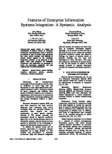
have been intended to be related. All that is required is a linking attribute. A linking attribute is a global attribute which has been mapped into more than one repository. By merging results from repositories based on like (equal) values for the linking attributes, all of the information in the repositories in which the linking attributes are mapped can be related. As an example., consider the setup shown in Figure 4. This example shows how a model of a
HotCup
MIND Model name
id
cup heater id ...
unitPrice
id ...
...
designer name picture contents ...
Rep: Repository1 DB: db1 GC: HotCup GA: id LC: HOTCUP LA: HOTCUPID
Rep: Repository1 DB: db1 GC: HotCup GA: id LC: HOTCUP LA: HOTCUPID
Rep: Repository2 DB: mmr GC: HotCup GA: id LC: HotCupTechDoc LA: hotCupID
Rep: Repository2 DB: mmr GC: Designer GA: picture.contents LC: HotCupTechDoc LA: designer.contents
HotCupTechDoc HOTCUP: NAME
HOTCUPID ... hotCupID
CUP: CUPID
designer
...
DESIG... description filename contents ...
Repository1:db1 Relations
Repository2:mmr Class Structure
Figure 4: Mapping the MIND model into two different repositories. HotCup is mapped into two different repositories. The attribute HotCup::id is used as a linking attribute by providing a mapping from it to a column in the ORACLE database and an access point in the multimedia repository. When a request is made for information from both of these repositories, the ISS will extract the information from the two repositories separately including values for the linking attribute. Then the information is merged based on like values for the linking attribute. This way, a request can be made which retrieves the HotCup name along with the picture of the designer of that HotCup in a single request, even though they are in different repositories. 15
IX
Issues and Implementation Decisions
The work on the ISS began in October 1991, and it represents over 8 person years of effort. Most of the code is written in AT & T C++ and also uses NIH classes (Gorlen, Orlow, and Plexico, 1990). The graphical user interface (client interface) of the ISS is built using C++ classes that encapsulate Motif widgets. Some of the issues and decisions we have made for the current system are: 1. Transaction versus session oriented: In building a system such as ISS, which needs to support multiple, concurrent users, there has to be a notion of processing transactions. However, from the context of individual users, it is useful to maintain a session orientation. To balance these requirements, we have decided to make the ISS server transaction oriented and to provide support to ISS client builders to develop session oriented clients. The login and access id mechanisms support this. 2. Static Schema: In our system, we have assumed that the schema will remain static during the time that users will be accessing information from the Information Sharing System. Trying to access the data while the schema or the map is being modified could result in inconsistent results. Therefore, we decided that the user interface cannot access the data or the model while the model or the map is being updated. 3. Information Access: Since we are trying to address the problems of large organizations that are geographically dispersed, the ISS must operate over a wide area network. We have used the current system over a wide area (between the University of Iowa and West Virginia University), and we get back answers to queries in a few seconds to a few minutes depending on the size of the query. We are currently doing a detailed performance analysis of our system. 4. DBA maintenance role: A system such as the ISS will never be deployed if the DBA is expected to be a C++ programmer. In our current strategy, we expect the DBA to develop the model using a graphical user interface (GUI). We also expect the DBA to provide mappings from the model to external repositories. The map representation has been simplified to make the maintenance task easier. X
ISS Graphical User Interface
The ISS User Interface (see Figures 5) allows users to interactively browse, search, and display information that resides in remote repositories. The ISS provides quick response even when multiple users are simultaneously accessing information. The data that a user can obtain through the interface can be a bitmap image of an item, a list of an item’s attributes, SQL query results, or a graphical view of the relationship among items in remote repositories. The user can also bring the viewed information locally into the user’s workspace. Figure 5 shows the ISS graphical user interface (GUI). The first horizontal pane shows the model. The second horizontal pane shows the query tree and the desired attributes. The third horizontal pane shows the conditions in the query. The first pane is divided into three vertical panes showing showing classes, relationships and attributes. The attributes one is interested in can be shown by bringing up selected portions of the model as a tree (in the second pane) and the desired attributes are selected from the tree. Conditions can subsequently be formulated using the GUI and they are displayed in the third pane. Figure 6 shows part of the results of the query formulated in 16
Figure 5. Graphical images can just as well be retrieved using the ISS. Figure 7 shows a graphical image we have retrieved. The ISS GUI enables users to do the following: Browse the model maintained in the ISS; Formulate a query (partly graphically) using the model; Store a formulated query and reuse it in future; View and browse the results of a query; Retrieve a specific instance of a class shown in the model, and Retrieve and display multi-media entities such as GIF files and Framemaker documents with voice clippings. XI
Status of the System
The ISS is part of a set of projects in concurrent engineering being developed as part of the DARPA Initiative in Concurrent Engineering (DICE) program. A prototype system integrating a relational database in ORACLE and a multimedia repository in VERSANT has been completed and is targeted for delivery to industrial pilot sites. Some of the pilot-sites in the DICE program are specific projects in General Electric Aircraft Engines, Westinghouse, MCC, and Lockheed. The ISS will be integrated into a single environment available to a team member to enable him/her to work effectively in a concurrent engineering environment by allowing him/her to communicate with others over a wide area network, coordinate his/her activities with that of other team members and the project as a whole, and share information using the enterprise model. We hope the lessons learned during the use at the pilot-sites will help in designing a better system in the future years. We plan to develop product, process and organizational models for at least a few industrial settings. XII Future of the System Our vision of the ISS is a generic system which may have multiple instances. Therefore, in a large enterprise, one would have a number of IS servers and the user can avail of the services of any server on the network. Each server will also be capable of serving multiple users and will allow both read and write access to the enterprise information which is being modeled, subject to security constraints. We envision this development to lead to a situation in which we have several cooperating ISS agents, so that if the information a user wants is not with one ISS agent, it will be passed to another in order to obtain the solution. In future versions of the system, we plan to provide better security, version and configuration management of the model, and integration with several different kinds of database management systems and other information repositories. We intend to augment the multimedia repository by including links to audio and video clips stored in CD ROMs, Laser Discs and video tapes. XIII Summary In this paper, we have described our ongoing efforts in the development of a collaborative environment for sharing information. A model-based methodology for accessing information that is scattered across an enterprise has been developed. The architecture of a system called the Information Sharing System (ISS) and the current status of the software have been described. The ISS 17
is targeted to be used at industrial pilot sites. The use of the model in searching and retrieving information eliminates the need for a user to know where and how the data is physically stored. This relieves the user from having to know multiple retrieval protocols and the different naming conventions of the different repositories. It also provides the user with a unified view of the entire collection of information regardless of where each piece of information is located. This allows the user to get an overall picture of the information as well as locate information which is related to information that is already known. We believe this system and its successors will significantly promote cooperative work among people using heterogeneous distributed information systems over a wide area. XIV References Bell Atlantic Software Systems, Morgantown WV. Knowledge Server Guide. May 1991 Christine Collet, Michael Huhns and Wei-Min Shen, “Resource Integration Using a Large Knowledge Base in Carnot,” IEEE Computer, 24(12):55-62, December 1991. S. Christodoulakis, F. Ho, and M. Theodoridou, “The Multimedia Object Presentation Manager of MINOS: A Symmetric Approach,” in Proceedings of the ACM SIGMOD International Conference on the Management of Data, May 1986. R.V. Guha and Douglas Lenat, “Cyc:A Midterm report,” AI Magazine, 11(3):32-59, Fall 1990. Keith E. Gorlen, Sanford M. Orlow, and Perry S. Plexico, “Data Abstraction and Object-Oriented Programming in C++,” John Wiley & Sons Ltd, 1990. D. Heimbigner and D.A. McLeod, “Federated Architecture for Information Management,” ACM Transactions on Office Information Systems, 3(3):253-278, July 1985. International Standards Organization, CADDETC 171 Woodhouse Lane Leeds LS2 3AR UK. EXPRESS Language Reference Manual. 1991. Douglas Lenat and R.V. Guha. Building Large Knowledge-Based Systems: Representation and Inference in the Cyc Project. Addison-Wesley, Reading, Mass. 1990. Stanley B. Lippmann. C++ Primer. Addison-Wesley Publishing Company, 1991. W. Litwin, L. Mark, and N. Roussopoulos, “Interoperability of Multiple Autonomous Databases,” ACM Computing Surveys, 22(3):267-293, September 1990. Y. Masunaga “Design Issues of OMEGA: An Object-Oriented Approach to Model Multimedia Database Management System” Journal of Information Processing, 14(1), 1991. Carlo Meghini, Fausto Rabitti, and Costantino Thanos, “Conceptual Modeling of Multimedia Documents,” IEEE Computer, 24(10):23-30, October 1991. S. B. Navathe et al., “Federated Architecture for Heterogeneous Information Systems,” in Proceedings of the National Science Foundation Workshop on Heterogeneous Databases. 1989. A.P. Seth, and J.A. Larson, “Federated Database Systems for Managing Distributed, Heterogeneous, and Autonomous Databases,” ACM Computing Surveys, 22(3):183-236, September 1990.
18
Darrell Woelk and Won Kim, “Multimedia information management in an object-orienteddatabase system,” Technical Report DB-046-87, MCC, Austin Texas, 1987
Figure 5: A query posed using the ISS graphical user interface. The Figure shows classes, relationships and attributes. A + sign next to an item means that it shuld appear in the final result, a - sign indicates that it is not needed.
19
Figure 6: Some of the instances selected for the query in Figure 5.
Figure 7: A graphical image of a coffee cup retrieved using ISS from the multimedia repository.
20