IEEE ISIE 2006, July 9-12, 2006, Montréal, Québec, Canada
Modeling Functional Requirements to Support Traceability Analysis Nihal Kececi*, Juan Garbajosa*, Pierre Bourque** Universidad Politécnica de Madrid (UPM) Technical University of Madrid E.U. Informatica. Ctra. de Valencia, Km. 7. E-28031 Madrid. Spain
[email protected] [email protected] ** Département de génie logiciel et des TI École de technologie supérieure 1100, rue Notre-Dame Ouest Montréal (Québec), Canada H3C 1K3
[email protected]
Abstract Traceability analysis is a technique that enables the verification of software requirements within the software life cycle. Within a context where there is a lack of common understanding of what must be traced, a number of methods have been proposed to implement software requirements traceability analysis, many of these methods dealing with software requirements expressed in natural language. This paper provides a graphical model to visualize software functional requirements that facilitates identifying functional traceability links. An application of the proposed model is illustrated through a case study taken from a process control system. Keywords: Functional traceability, requirements verification, traceability analysis.
I.
INTRODUCTION
Requirements specifications for software consist of a number of abstraction levels, derived through successive decompositions of the software under development or being maintained. One of the major challenges within large-scale software engineering is the management of these requirements notably because software requirements are generated, used and changed throughout the software life cycle by a number of different technical and commercial groups. The SWEBOK Guide defines verification as “an attempt to ensure that the product [software] is built correctly, in the sense that the output products of an activity [within the software life cycle] meet the specifications imposed on them in previous activities” [1]. Validation deals with ensuring that the product fulfills its intended purpose. This paper deals with traceability analysis within the context of software verification rather than within the context of software validation. The completeness of the verification of software requirements is fundamental to effective requirements management. The complete software requirements verification process shows whether a software component behaves in
1-4244-0497-5/06/$20.00 © 2006 IEEE
accordance with its previously stated software requirement specifications. The importance of software requirements cannot be overstated since all subsequent phases of the software life cycle are dependent upon these software requirements. Developing and managing software requirement specifications represent an especially difficult challenge. Experience has shown that some of the reasons why errors tend to occur in the software requirements phase are as follows: (1) misunderstanding or misinterpretation of software requirements, (2) incomplete and inconsistent software requirements, and (3) software requirements written in natural language that are ambiguous, inconsistent, and incomplete. The result of the software requirements elicitation and specification process is often a long document that is difficult to read and is even more difficult to design and code from. Also, when changes are needed, processes are often not in place to determine how other software requirements are affected by particular changes. Software requirements traceability analysis is therefore an essential activity to support the verification of software requirements as well as to manage changes. The ability to trace the logical and physical links between software artifacts including different levels of requirements is essential and critical to the development of complex software. In this section we discuss the importance of software requirements in the software life cycle, the verification of software requirements, and the role of software requirements traceability analysis within the software verification process. Section 2 reviews current verification methods for software. Definitions of the terms used in this paper are introduced in section 3. A modeling method for graphical software requirements analysis is discussed in section 4, and a case study is presented in section 5. Conclusion and lessons learned are discussed in Section 6.
3305
II. SOFTWARE REQUIREMENTS VERIFICATION METHODS To deal with inconsistent and incomplete software requirements, many approaches to the verification of software requirements have been developed over the last years. According to a survey and assessment of verification methods of conventional software [2], software requirements and design verification methods consist of four major categories and various subcategories. These major categories are described as follows and are summarized in Table 1. TABLE 1 CATEGORIES OF SOFTWARE VERIFICATION METHODS
Category Formal Methods Semi-formal Methods
Review and Analysis Traceability Analysis
Description Mathematical Verification of Software Requirements: Translates software requirements into mathematical form to analyze various properties. Requirements Language Analysis: Express software requirements in a special requirements language and analysis of results for completeness, consistency, feasibility, testability, etc. Review and analysis by trained personnel of the adequacy of software requirement specifications using a detailed preestablished set of criteria and procedures. Identification of individual software requirements entities and tracing of these to design entities and from the design entities to implementation entities.
A.
Formal Methods: Formal methods involve mathematical and logical representations for expressing relationships among data and for expressing the processes which interact with them. Mathematical representations produced early in the software life cycle, from the stakeholder requirements definition document, the software requirements specifications, and the software design documents may then be subjected to formal deductive reasoning to detect anomalies or defects regarding, for example, correctness, contradiction, completeness, and consistency. While formal descriptions are valuable, the state of the art has not evolved to a point, yet, where they can be very widely applied. In particular, the number of people who could be trusted to make formal descriptions of non-trivial software is quite limited. B. Semi-Formal Methods: Semi-formal methods are less difficult to apply than formal methods. They often involve notations with rigorous constraints on notably the selection and sequencing of operators to achieve the goal of analyzing software requirement specifications within well defined boundaries. One major advantage is often their graphical mode, a characteristic
that facilitates simulation or animation of software requirement specifications and designs. But formalization itself cannot guarantee defect detection, nor can it prove that the software requirement specifications are correct. C.
Review and Analysis: A commonly applied method of software verification is the review and analysis of the stakeholder requirements definition documents and the software requirement specifications. Such a review and analysis is carried out by trained personnel to investigate their adequacy using a detailed pre-established set of criteria and procedures. A group of reviewers is constituted with a mandate to look for errors, mistaken assumptions, lack of clarity and deviations from standard practices. Reviews may be constituted on completion of the stakeholder requirements definition document, the software requirement specifications, the baseline specifications for a new release, etc. D. Traceability Analysis: Traceability analysis notably establishes the relationships between software requirement specifications and software design, matching elements of one to those of the other. Once the matching has been completed, all that remains is either a set of unmapped software requirement specifications, or a set of unmotivated or unintended functions that were inserted in the software design artifacts. Traceability analysis may also be applied between different levels of software requirements such as between the stakeholder requirements definition document and the software requirement specifications. Within the context of a lack of common understanding of what must be traced, many methods have been proposed for diverse applications of software requirements traceability analysis and many of them deal with software requirements expressed in natural language [3, 4]. II. KEY CONCEPTS AND DEFINITIONS Functions are discrete actions that must be performed. Functional analysis begins by identifying top-level system functions and decomposing these into a hierarchy of subfunctions to form a functional architecture. The objective is to break the system down into sub-functions which can be performed by people, hardware, and software, and which, when combined with other sub-functions, will achieve the performance of the higher-level system function. The purpose of functional requirements traceability analysis at the system level is to determine if all the functional requirements have been mapped to detailed system specifications and if these, in turn, have all been allocated to the functional components of the software architecture if these system specifications are allocated to software. The Software Functional Specification (sometimes called a Functional Architecture) contains a high-level diagram of the logical software architecture including interfaces to other systems and software. The software is divided into functional
3306
components, which are further described in the software design descriptions produced in the next phase. The Functional Specification describes how the software requirement specifications will be met in terms of the software’s logical architecture. To avoid confusion, many of the terms used in this paper are defined below.
o
Function: “(1) A function is a module that performs a specific action, is invoked by the appearance of its name in an expression, may receive an input value, and returns a single value” [5]. When a function is decomposed, sub-functions can be identified Even though this definition is technical in nature, it is deemed to be useful because of its emphasis on the discrete nature of a function.
o
Functional Characteristics: Inputs, outputs, process (algorithms), and interfaces of a function are defined as functional characteristics in this paper [5]. Functional Requirement: “A requirement that specifies a function that a system [software] or system [software] component must be able to perform” [5]. Functional Specification: “A document that specifies the functions that a system [software] or component must perform” [5]. Functional User Requirements (FUR): “The term Functional User Requirements is a sub-set of the user requirements. The FUR represent the user practices and procedures that the software must perform to fulfill the user’s needs. FUR exclude Quality Requirements and any Technical Requirements” [6]. Traceability: Definitions or descriptions of traceability that can be found in software engineering standards include: o “The degree to which a relationship can be established between two or more products of the development process, especially products having a predecessor successor or master-subordinate relationship to one another; for example, the degree to which the requirements and design of a given software component match” [5]. o “A Software Requirements Specification (SRS) is traceable if the origin of each of its requirements is clear and if it facilitates the referencing of each requirement in future development or enhancement documentation.” Forward and backward traceability are also recommended [7]. o “Traceability […] means that the document in question is in agreement with a predecessor document to which it has a hierarchical relationship. Traceability has five elements:
o o
o
the document in question contains or implements all applicable stipulations of the predecessor document, A given term, acronym, or abbreviation means the same thing in all documents, A given item or concept is referred to by the same name or description in the documents, All material in the successor document has its basis in the predecessor document, that is, no untraceable material has been introduced, and The two documents do not contradict one another” [8].
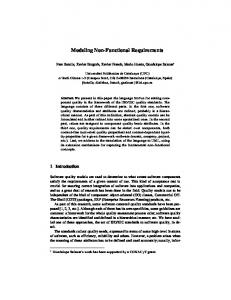
III. MODELING METHOD FOR GRAPHICAL REQUIREMENTS ANALYSIS Graphical Requirement Analysis (GRA) is a method for translating functional requirements expressed in a text format to a graphical format. It is also proposed as a traceability analysis method for system and software requirements The GRA modeling core concept was derived from a system engineering technique called the Master Logic Diagram (MLD) [9,10,11]. This technique has been used to model complexity for system diagnostic purposes. GRA includes, as well, a mapping to the COSMIC-FFP method [6] for measuring software functional size though this topic is not discussed in this paper. As shown in Fig. 1, the GRA modeling method adopts the following graphical language notation: Module 1: A rectangle in the centre represents a module or Functional User Requirement in a multilevel hierarchy. External I/O: The rectangles on the top and on the left represent external input and output sets. User inputs, sensor outputs, system variables, and outputs of another module are examples of such external input and outputs. Internal I/O: The numbered circles represent the output of a sub-module which will be an input to another sub-module within a time sequence, as shown in Fig 1. Sub-module: These are illustrated with decision logic symbols in Fig. 1. Sub-modules can be mathematical operators, decision algorithms, etc. Boundary: This is identified by the entry and exit points of a Functional User Requirement or module.
1
3307
The terms of module and function are used interchangeably.
The description of the Vessel Water Level Controller function was taken from the System Requirement Specifications, and is as follows: “The level controller provides the dynamic level position inside a given component along with the current feed water line and steam line mass flow rates. The output consists of the mass flow rate of the FILL component, which provides the inlet flow of the feed-water system.”
OUTPUT
A module
6 5
A sub-module
5
Internal I/O
4 4
Step 1: Identifying the external I/O
3 3
To achieve the Vessel Water Level Controller function, five inputs were identified in the System Requirement Specification as follows. These were traced forward from, and backward to, the User Manual to verify their correctness.
2 1
2
1
User/operator inputs
Sensor outputs
Outputs of another function/module
Any hardware action
INPUT 1
INPUT 2
INPUT 3 INPUT n
Fig. 1. Graphical Requirements Analysis (GRA) Notations
A general strategy for functional decomposition is to define a Functional User Requirement (FUR) as a mapping from inputs to outputs. Ideally, traceability analysis proceeds in a top-down fashion, first identifying the functions associated with the software as a whole. Each level of detail in the hierarchy provides detail about the processing steps necessary to accomplish the more abstract function defined one level above. The decomposition process is repeated until some lowest level of sub-functions is reached. On the left side, the external input sets are linked to sub-modules. Some external inputs may be used by multiple sub-modules. In a complete decomposition of a Functional User Requirement (FUR), the functional hierarchy specifies the sub-modules, the internal inputs needed to perform these sub-modules, and the internal outputs resulting from these sub-modules, as well as their interrelationships. Any external output of a module can be an input to another module or vice versa. IV. A CASE STUDY: An illustration of an application of the GRA method on a Vessel Water Level Controller, a functional user requirement (FUR’s) in a process control system2, is presented in this section. To build the GRA model, the functional characteristics (input/output/process) of the Vessel Water Level Controller which is a system level requirement, were searched through the various documents produced during the system and software development process. 2
X1(meter) should be provided with the vessel down water level, which could be provided by type 106 signal variable. X2 (kg/sec) should be provided with the current time step feed water line mass flow rate. X3(kg/sec) should be the current time step steam line mass flow rate. c1 (meter) is the user-desired vessel collapsed water level position, c2 (kg/sec) is the nominal steady state feed water line mass flow rate (kg/sec) Control block number 202 was identified in the User Manual as the Vessel Water Level Controller function. The control block was described as follows: Control Block no.: 202 Control Block name: Vessel water level controller Control Block Mathematical Operation: X (out) = f (X1, X2, X3, c1, c2) Block Inputs: X1, X2, X3 Block Constant: c1, c2 The External I/O of the Vessel Water Level Controller is illustrated in the GRA framework with rectangles outside the functional boundary in Fig. 2. Step 2: Identifying Sub-modules and Internal I/0 The control block function operators or sub-modules belonging to the Vessel Water Level Controller were identified from the System Design Specification (SDS). These are traced forward from, and backward to, the User Manual. To achieve the process goal of each sub-module as listed in Table 2; their internal inputs/outputs were searched using a functional decomposition technique. The application of the GRA method notably identified that SUBT 54 had an incorrect control block number. This has been replaced by ADD 3 in Figure 2.
For reasons of confidentiality, no reference is cited here.
3308
Table 2: Sub-Modules of Control Block 202 Previously Identified Sub-Modules Control Block # 23 26 56 59 11 54 59 56
Control Block Type & Name ING (Integrate) LAG First-order lag SUBTC (Sum constant) WSUM (Weighted summer) DEAD (Divide) SUBT (Subtract) WSUM (Weighted summer) SUBTC (Sum constant)
Xout=f (X1,X2,X3 C1,C2) 202
Sub-Modules Identified by Using the GRA Method Control Block Number and Type ING 23 LAG 26 SUBTC 56
8 3
7 26 6 59
WSUM 59
.
3 59
DEAD 11 ADD 3 WSUM 59
2 1
23
56
SUBTC 56
5 X(1)(m) Vessel Water Level
56
SVT 106
The external inputs identified in step 1 are then mapped to the internal inputs of the lowest level of sub-module obtained using a functional decomposition of the system requirement in step 2. As shown in Fig. 2, the inputs of the Control Block Functions or sub-modules 11, 3, 56, and 23 are mapped to the external inputs. After verifying the correctness of the external inputs in the GRA method, these inputs are mapped to the System Requirement Specifications; leading to either a set of unmapped requirements or to a set of unnecessary requirements. Models such as Figure 2 are built from top to bottom (that is from the User Manual to the System Requirement Specifications, the System Design Specifications and eventually to the Software Requirement Specifications), and traceability analysis is executed from bottom to top (that is, from the Software Requirement Specifications to the System Design Specifications, the System Requirement Specifications and to the User Manual). Functional characteristics (internal I/O, external I/O, subfunctions or sub-modules) can be incorporated into a multilevel hierarchy using the GRA modeling method.
Cbcon1(m): Water level set-point 4
X(2)(kg/sec) Current time step feed-water line mass flow rate (mfw)
11
X(3)(kg/sec) Current time step steam line mass flowrate (ms)
Cbcon2(kg/sec): nominal steady state feed-water line mass flowrate
INTERNALI/O 1
Water Level
2
Int. Lev. Err
3
(Ki+Kp)term
4 5
SUB-FUNCTIONS
56
SUBTC
23
INT
59
WSUM
11
DEAD
26
LAG
3
ADD
FW
S
∆m
(dem)
7
∆m
(act)
FW
FW
X(2) (kg/sec) Current timestep feed-water linemassflowrate (mfw)
Xout=f (X1,X2,X3C1,C2)
X(3)(kg/sec) Current timestep steamlinemassflowrate (ms)
Cbcon2(kg/sec): nominal steady statefeed-water linemass flowrate
FW
m
SVT 106
Cbcon1(m): Water level set-point
FW
6
8
EXTERNALOUTPUT
X(1) (m) Vessel Water Level
m
m -m
EXTERNAL(SYSTEM ANDUSER) INPUTS
202
Level Controller
Fig. 2. Analyzing Water Level Control Function using the GRA Method
V.
LESSONS LEARNED AND CONCLUSION
This paper discussed a modeling method to support software requirements verification and to facilitate traceability analysis of software requirements. The proposed method has the following strengths: o Using a graphical presentation instead of natural language to specify software requirements at various levels of abstraction can reduce inconsistencies, incompleteness, ambiguities and better reveal requirements that are not specified. o A graphical presentation of requirements helps to visualize functional interrelationships between system
3309
o
requirements and software requirements as well as between stakeholder requirements and software requirements . Even though these topics are not presented in this paper, effectiveness of test cases and impact analyses are an integral part of the model.
A future research opportunity to be investigated regarding automation of the GRA method is the link between the proposed method and the current research and development on model-driven software development [12]. An investigation of how the proposed method can benefit from a stronger integration with the COSMIC-FFP functional size measurement method should also be pursued [6]. ACKNOWLEDGEMENTS In this work Universidad Politécnica de Madrid has been partially supported by the AGMOD project, Ref. TIC200308503, funded by the Ministry of Education of Spain. REFERENCES [1]
[2]
[3] [4] [5] [6] [7] [8] [9] [10]
[11] [12]
Abran A. and Moore J. W. (Exec. Eds), Bourque P. and Dupuis R. (Eds) "Guide to the Software Engineering Body of Knowledge,", 2004 Version, IEEE Computer Society Press and also published as ISO Technical Report 19759, 2004. Groundwater E.H., Miller L.A., Mirsky S.M. Guidelines for the Verification and Validation of Expert System Software and Conventional Software. Survey and Document of Expert System Verification and Validation Methodologies NUREG/CR-6316, SAIC-95/1028. Vol.1-7. . 1995 Orlena C.Z., Anthony C.W., Finkelstein. “An Analysis of the Requirements Traceability Problem, ,http://www.cs.ucl.ac.uk/staff/A.Finkelstein/papers/rtprob.pdf Jackson, J., “A Key-Phrase-Based Traceability Scheme, Tools and Techniques for Maintaining Traceability during Design,” IEEE Colloquium, Computing and Control Division, Digest No: 1991/180 IEEE, Std. 610.12: Standard Glossary of Software Engineering Terminology. 1990. ISO/IEC, ISO/IEC 19761: Software Engineering - COSMIC-FFP - A Functional Size Measurement Method, International Organization for Standardization, Geneva, Switzerland. 2003. IEEE, Std. 830: Guide to Software Requirements Specification,” 1998. DoD, Std-2167A: U.S. Department of Defense Military Standard: Defense System Software Development, Washington, D.C. 1988. Modarres M.. Functional Modeling of Complex Systems Using a GTSTMLD Framework. Proceeding of the 1st International Workshop of Functional Modelling of Complex Technical Systems, Ispra, Italy. 1993. Hu Y-S, Modarres M., Applying Fuzzy-Logic-Based Hierarchy for Modelling Behaviours of Complex Dynamic System. System and Software Computing in Nuclear Engineering, Da Ruan ed., SpringerVerlage. 1999. Kececi, N., M. Modarres, and C. Smidts. “System Software Interface for Safety-Related Digital I&C Systems”, European Safety and Reliability – ESREL’99 Conference, TUM Munich- Garching, September 13-17, 1999 Sendall, S.; Kozaczynski, W. Model transformation: the heart and soul of model-driven software development. IEEE Software, Vol. 20, No 5, p.42-45 2003.
3310