The application areas well covered by existing ... further development is required are pointed out. Some of ... data entry windows, but not in diagrams). Though it.
Modeling languages and tools: state of the art Audris Kalnins, Janis Barzdins, Karlis Podnieks Institute of Mathematics and Computer Science University of Latvia Raina bulv. 29, LV – 1459 Riga, Latvia E-mail: { audris, jbarzdin, podnieks }@cclu.lv KEYWORDS Modeling, Business Process Modeling, Object Modeling, Unified Modeling Language (UML), Modeling Tools. ABSTRACT The paper presents some discussion on current issues of modeling languages and tools. Two areas are considered: business modeling and Unified Modeling Language based modeling (object modeling). The application areas well covered by existing languages and tools and those where further development is required are pointed out. Some of the authors' experience in solving current modeling problems is presented, especially in object modeling area.
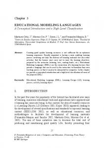
It should be noted, that IDEF0 – the simplest of them – is still used as an official standard in the USA. To illustrate the language style, the papers shows small fragment of an Order processing example in some of these languages. prov ides input f or
Produc t needed
Order New order
Reque s t s erv ic e
Order c orrec t
Cus tomer Order r ejec ted
S ale s as s is tant
Pay
Fill order ex ec utes
Stoc kroom pers onnel
Deliv er order
Order deliv ered
INTRODUCTION
V alidate order
Fig. 1. Business process in ARIS EPC Customer
By modeling, even narrowed down to the IT area, one can understand very different issues – from building class diagrams to writing a set of differential equations. Yet when browsing the Web or visiting Amason.com, you see two hot topics in modeling: • business process modeling • Unified Modeling Language (object modeling) Certainly, a separate issue, always interesting, though to a specific audience, is data modeling (ER- modeling), but we will not consider it here. The paper presents a brief overview of available languages and tools in the two named areas. A modeling approach is basically determined by its language. Since all this modeling is graphic, a modeling language is determined by its diagram types and relations between them.. BUSINESS PROCESS MODELING The business modeling area has been extremely active in mid-nineties. Now it has stabilised on quite a few popular business modeling languages. These are ARIS(EPC) [Scheer], IDEF0 [Hill], IDEF3, as well as languages based on CATALYST [CSC] notation or simple flowcharts.
Request service 1 Receive rejection
Pay
L15
1
L
&
L18 J1 L8 Sales assistant Order correct L12 Fill order
L19
Order rejected Validate order
L
X
&
3
J1
Deliver order 4
J
Fig. 2. Business process in IDEF3 (in SA2001) Despite different graphical symbols used, their basic syntax and semantics (or essence of their metamodels) is quite similar. The notation actually is "flowchart-based". There are activities (functions, UOBs etc), linked by control flows (sometimes also object flows), with decisions (branches), fork/join symbols and merges governing the control flow. The performer of an activity can be specified, most frequently by the swimlane notation. An activity may be refined by another diagram of the same type. The standard semantics of a business process is that, starting from a sort of a start symbol, activities are sequentially executed in the order which is prescribed by the corresponding control flows, with
possible concurrent execution, where the diagram explicitly prescribes this. The UML activity diagram (formally belonging to the second area covered by this paper) actually falls into the same category. The activity diagram has become widely accepted in UML only recently with the advent of UML version 1.3. Since then it has been admitted that business modeling is a proper part of Unified Modeling approach.
Customer
Request service
Sales assistant
Order [New]
Stockroom personnel
Validate order
New order
Order rejected
Validate order Sales assistant
Order
Order correct Placed order
Receive rejection Customer
Fill order Stockroom personnel
Pay Customer
Deliver order AND Sales assistant "1d"
Fig. 4. Business process in GRADE A comparison of business process modeling languages with respect to their functionality is given also in [Kalnins et al 1998].
[Order correct] [Order rejected] Order [Placed] Pay
Request service Customer
Fill order
All the mentioned business modeling languages are well supported by tools. The biggest share of the market is taken by the ARIS tool [Scheer], supporting the ARIS language. But the greatest number of tools exist for IDEF0 and IDEF3, the most popular tools being System Architect 2001(Popkin Software) [SA 2001] and BPwin (Computer Associates) [Bpwin].
Deliver order
Fig. 3. Business process as UML activity diagram None of the languages mentioned contain formal numeric activity attributes such as activity duration, branch probabilities, input event frequency etc. These properties are delegated to the respective simulation extensions defined by the corresponded tools (and therefore visible only in corresponding data entry windows, but not in diagrams). Though it makes the modeling language definition very simple, frequently even for a qualitative assessment of a business system via its model this approach is to simplistic. A different approach is taken by the GRAPES-BM [Kalnins et al 1996] language, where there is one language for modeling and simulation, the simulation-relevant numeric attributes are part of the language definition. Though it makes language definition more complicated, it permits also quantitative assessment of model without simulation (if necessary, the tool can "hide" additional data in diagrams, to retain high-level diagram readability). One more distinguishing feature is more concurrency in default task (activity) semantics. In accordance with this, the flow join and merge is generalised to the universal triggering condition concept.
Business modeling languages and the business modeling itself serve two distinct roles. The first role is the Business process reengineering (BPR). Here the goal is to investigate business processes of a company and to document (map) them in a more or less formal way. The most important aspect to be covered is to analyse the enterprise-wide processes, by means of which the products or services of the company are produced. The existing (“as-is”) business model is obtained. On the basis of this model process improvements can be discussed. These improvements are documented in one or more to-be models of the company. The models must have their quantitative aspects well specified. The merits of proposed improvements can be discussed on the basis of these models and the best improvement version found. Simulation is also frequently used for this purpose. Most of business modeling languages are specially built for this purpose. The other application of business modeling is in the first stage of IT system development. The requirements for a complicated IT system cannot be specified if the business processes which must be served by the system are not well documented. All the above-mentioned business modeling languages can be used successfully for this purpose, but UML activity diagrams were specially introduced for this goal. The main objective here is to document as precisely as possible the logic of business processes. On this basis the business rules which
must be incorporated in the components of the IT system can be found. In contrast to the previous application of business modeling, the quantitative aspects of business processes are less important here. Several aspects of this application currently are not well supported, neither by language facilities nor tools. From the language side, good facilities to associate the main business process components – activities (tasks) to the proposed system architecture and structuring are missing. A very important deficiency is an inability in any of the business modeling languages to associate effectively the man-machine interaction activities to the corresponding screen forms. Authors of this paper are currently working on this problem. From the tool side, the possibility to transfer (even partially) the relevant knowledge on activity sequences to software component interaction specification would be highly desirable. The issue of linking activities to screen forms is hard also for tools. Some partial solutions to this problem are available in GRADE. Similar to the previous application is also the use of business process diagrams for workflow definition. The Workflow Management Coalition [WfMC] proposes state diagrams as the formalism for workflow definition, but most of practical workflow definition tools use some sort of business process diagrams. OBJECT MODELING AND UML Quite a different situation is in the area of object modeling. After the “method wars” in mid-nineties, there is one dominating language – Unified Modeling Language (UML) [Rumbaugh 1999]. Though not formally standardised, due to the efforts of OMG it has become a de facto standard. Currently OMG has finalised the UML version 1.3, but the development of a more radical improvement – the version 2.0 is under way (it is expected to appear in 2001). The only real contender to UML is OML [OPEN Consortium]. But its share is small. Despite its clear naming, UML has a dual role – of an object-oriented modeling language and a design language for OO development of systems. Currently the second aspect is more elaborated, at least there are clear mappings between UML class diagrams and their implementations in OO programming languages. This mapping is supported by tools in both directions. But the pure modeling aspect of UML is significantly less elaborated. It concerns the use of class diagrams for high-level conceptual modeling
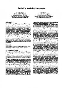
of systems, as well as the use of various “dynamic” diagrams of UML – use case, activity, sequence, collaboration and state for behaviour modeling. Certain usage of state and collaboration diagrams for low-level design specification is quite clear. But the high level behaviour description is unresolved to a great degree. There are some local deficiencies in the semantics definition of behaviour description [Hitz]. But the most essential cause is the lack of clear guidelines in the language definition how the diagrams are interrelated. The official UML “usage guide” - the Rational Unified Process (RUP) does not solve this problem either. It concentrates more on the organizational aspects of the development process (the roles in the development team, reports produced etc) than on pure methodological aspects how a correct sequence of UML diagrams could be obtained. A research both making the language more coherent in this area, and producing reasonable guidelines for the usage is still needed. Some short discussion on modeling guidelines and clarification of UML language semantics in the context of high level modeling is given here. The first issue is building of conceptual class diagrams for complicated systems. The methodology in this area has been started by Rumbaugh in his fundamental book [Rumbaugh 1991] on object modeling but somehow has not been consistently continued in the context of UML. So even simple rules how to choose class and association/role names so that they represent the real world entities in the most easy-to read way are of high value (there is a lot of advice available how to do it for software design documentation). An important rule is a consistent positioning of role names with respect to association lines (by the way, supported by very few tools, one of them GRADE). A simple rule (“what could be the class instances in a snapshot of the system”) helps to assign correct cardinalities of associations. These are just some rules available in this area. Further research here could be linked to pure linguistic aspects of a precise description of a system. Important issue in transition from the first conceptual class model to a more distributed description of the system aspects by separate UML diagram types is the consistent use of stereotypes in class diagram. Fig. 5 (produced by GRADE) shows some of the authors’ experience how the initial view on both static structure and actions can be represented by a stereotyped class diagram. The simultaneous presentation of both these aspects in one diagram permits one to get an easier understanding of a complicated system.
CKI agent
receives Passenger has
CONCLUSIONS
inspects
performs
1 Ticket
1..*
based on
Acceptance for Flight
Flight Coupon
The current trends in both business and UML-based modeling have been discussed. Some of the areas where there are problems both in modeling methodology and language support have been described. Some suggestions how the tool support should be improved are also given. REFERENCES
Assigning of Boarder number and Preparing of Boarding pass results in 1 Boarding pass Boarding number
Baggage checking and printing of Bag tags results in
Bpwin, 1999, Bpwin Product overview http://www.cai.com/products/platinum/appdev/bpwin_ps. htm
* Bag tags Boarding number
COOL:Jex, 2000 COOL:Jex Product Info http://www.sterling.com/content/prod_serv_factsheet.asp ?id=90&plid=2&pid=8&sid=1 CSC 1995 CSC Catalyst Methodology, CSC Inc,
Fig. 5. Conceptual model as a GRADE class diagram
Hill, S.C. 1994 A Concise Guide to the Idef0 Technique : A Practical Approach to Business Process Reengineering, Enterprise Technology Concepts Inc.
One more issue is the behaviour description in UML and how it is related to static structure description. Besides the problems common to general business modeling and discussed already in the previous section, an important issue is how to structure use cases and the corresponding activity diagrams so that a well structured and readable description of the desired system fundamentality is obtained. Here some formal guidelines also have been proposed by the authors.
Hitz, M., Kappel, G. 1999 UML @ Work, dpunkt.verlag, Heidelberg.
UML is well supported by tools, there are about 70 of them in the market. The unchallenged leader is Rational Rose (Rational Software) [Rational Rose 98], with some real share belonging to SELECT Enterprise (Princeton Softech) [SELECT], PLATINUM Paradigm Plus (Computer Associates) and COOL:Jex (Sterling Software) [COOL:Jex]. All the tools support well the low level design, close to the implementation, especially so called round-trip engineering. But the pure modeling aspects and high-level design is much less supported. This area is more demanding in good graphics capabilities for easy drawing of large diagrams, smart wizards supporting a modeling methodology, natural incorporation of multimedia-style description of key objects etc. Currently most of the tools does not support these features. In principle, UML activity diagrams could be used for full-scale business modeling, including simulation, but no tool currently supports this. Very few tools currently support all features of UML activity diagrams according to UML 1.3, even the latest version of Rational Rose (v. 2000e) still has deficiencies here, e.g., concurrent object flows are not supported.
Kalnins, A., Barzdins J. et al. 1996 Business Modeling Language GRAPES-BM and Related CASE Tools. Proceedings of the Second Baltic DB&IS'96, Institute of Cybernetics, Tallinn. Kalnins, A., Kalnina, D., Kalis, A. 1998 Comparison of Tools and Languages for Business Process Reengineering.- Proceedings of the Third Baltic DB&IS'98, Riga. OPEN Consortium OPEN Modeling Language (OML) Reference Manual http://www.omg.org/docs/ad/97-0124.pdf Rational Rose 98. 1998 Using Rational Rose, Rational Software Corporation. Rumbaugh, J., Blaha, M. Premerlani, W. Eddy, F. Lorensen, W. 1991 Object-oriented Modeling and Design, Prentice-Hall, Rumbaugh, J., Booch, G., Jackobson, I. 1999 The Unified Modeling Language Reference Manual, Addison-Wesley. SA 2001, System Architect 2001, http://www.popkin.com/ Scheer, A.W. 1999 Aris-Business Process Modeling, Springer Verlag SELECT, 1999 SELECT Enterprise Product Info, http://www.selectst.com/products/ProductInfo.asp?9 WfMC 2000 WfMC Standards: Interface 1 http://www.aiim.org/wfmc/standards/docs/if19910v11.pd f