contact). 3. Relieve and suppress the tumbling motion (after. If we illustrate the change of a typical velocity, it ... Inertia Tensor" and virtual masses, which are an ex- tended version of the concepts ... rgh E R3 : vector from total mass center of the system. v h E R3 ... where H* E Rnxn is the inertia tensor for free-floating systems ...
Modeling of Collision Dynamics for Space Fkee-Floating Links with Extended Generalized Inertia Tensor Kazuya YOSHIDA Ryo KURAZUMEt Naoki SASHIDA Yoji UMETANI Dept. of Mechanical Engineering Science Tokyo Institute of Technology 2-12-1, O-okayama, Meguro-ku, Tokyo 152, JAPAN (tFujitsu Laboratories LTD.) Abstract
arms to chase the target, neverthless the investigation on the problems of collison dynamics and release control, in the second and third phases is indispensable for practical space projects. We should comprehend the way to pre-estimate the magnitude and direction of impact force or acceleration of the robot from information on a relative velocity between the hand and target just before the contact, and develop the method to relieve the tumbling motion after the contact. In earlier work, Shimoji et al.[6]attempted to simulate robot motion in the phase 3 based on the sensor signal measured at the phase 2 using their hardware simulator. But it is difficult to sense and estimate the impact force precisely, because impact is very highspeed phenomenon and the force sensor signal is very weak for noise. Yamada and Tsuchiya [7]theoretially treated the force control between a manipualtor hand and a floating target: that is an interesting attempt but their focus was limited in a static force control. To find a clue to the investigation on collision dynamics, this paper deals with a basic formulation of motion dynamics of a free-floating link system, by developing a new concept named "Extended Generalized Inertia Tensor" and virtual masses, which are an extended version of the concepts originally established by Asada [@I. The purpose of this paper is to find a velocity relationship just between the phases 1 and 3 without sensing the impact force, paying attention to the principle of nature that total momentum is conserved throughout all phases.
This paper presents a basic formulation of motion dynamics of a free-floating rigid-link system, to establish a basis of the collision dynamics. The authors propose a new concept named "Extended Generalized Inertia Tensor (Ex-GIT)", which is an extended version of the GIT for ground-based arms, and discuss the virtual mass concept. By means of the concepts, they formulate the collision problem focusing on a velocity relationship j u s t before and after the collision without sensing the impact force, but considereing the momentum conservation law.
1
Introduction
Space has been attracting special interest as a new application field of robotics. In space environment, everything is freely floating, hence dynamic behaviour of mechanical links is different from the ground-based systems. In order to manipulate a tumbling target by a space arm as shown in Fig.1, we have to deal with the problem of dynamics and control in the following three different phases. 1. Chase the target (before contact with the target).
2. Catch and grasp the target by the manipulator hand (at the moment of contact). 3. Relieve and suppress the tumbling motion (after contact).
If we illustrate the change of a typical velocity, it will be discontinued at the phase 2 by the impact force, as shown in Fig.2. Recently we can find a lot of studies on dynamics and control of space robots (for example [1-5]),however most of them focus their attention on the problem in the first phase: the methods for control of space
2
Kinematics and Dynamics of FrepFloating Chain of Links
Let us consider a chain of rigid links composed of n+l bodies. The bodies are connected with rotational joints and freely floats in the inertial space, as shown in Fig.3.
899
0-8186-2720-4192$3.00 81992 IEEE
Authorized licensed use limited to: TOHOKU UNIVERSITY. Downloaded on April 07,2010 at 04:02:23 EDT from IEEE Xplore. Restrictions apply.
Define the symbols as follows: n : number of joints
m; : mass of link i w : total mass of the link system (E
m;)
I; E R 3 x 3 : inertia tensor of link i with respect to its mass center
r,, E R3 : vector from total mass center of the system to mass center of link i
E R3 : vector from total mass center of the system
rgh
to hand (where external force acts)
Fig.1 Future space mission: manipulation of a tumbling target by a space arm [l].
I'
wh
E R3 : angular velocity of hand
T E
: joint angle vector
= ($1~42,...,$n)T
R" : joint torque vector = ( ~ 1 ~ 7 2 ,...,Tn)*
E E R 3 x 3 : 3 x 3 identity matrix I E R 6 x 6 : 6 x 6 identity matrix
+
where i = 0 , . . . ,n and all vectors and tensors are described with respe_ct to the inertial coordinate frame. An operator { } for a vector r = [x,y,zIT is defined as
t"
Velocity v
phase 1
E R3 : linear velocity of hand
4 E Rn
InipscL Force 3
YT
vh
[.i
-"0y
1
-2
;yX I .
b T t M E
phase 2
plisse 3
Fig.2 Three phases in collision problem
applied force 3
Let us suppose a general case that a total momentum of the system is not zero but the total mass center (point G in Fig.3) moves in the inertial frame with linear and angular velocity: v g , w g .If we describe the total linear and angular momentum with respect to G using P,,L,, then
/ where n
I,
E(&-
m;igiigi
E R3x3
(2)
;=o
U
i.,
.
is the inertia tensor of the chah with respect to G. If the kinematic relationship of the chain is considered, the hand velocity is expressed as follows (71:
wh
Fig.3 A chain of free-floating rigid links
900
Authorized licensed use limited to: TOHOKU UNIVERSITY. Downloaded on April 07,2010 at 04:02:23 EDT from IEEE Xplore. Restrictions apply.
where
G*
(12) (11) is the equation of motion of the hand (the point where the forces act) associated with the external forces F,and the tensor G* represents dynamic characteristics of this system. The authors stress significance of this tensor and propose to call "Extended Generalized Inertia Tensor (Ex-GIT)", because it is an extended concept of the conventional GIT [8]for a ground-based chain, to the space free-floating chain. Let us examine the relationship of GITs in particular conditions. First of all, in free-joint case with no joint resistance, p = 0 , the Ex-GIT behomes as followS.
and J* E RGxn is the Generalized Jacobian Matrix for free-floating systems [3,4]. Defferentiating (3) with respect to time, we obtain the hand acceleration.
On the other hand, the equation of motion of the free-floating chain can be written in the following form: H*$ c*(& = 7 J*TF (6) where H* E Rnxnis the inertia tensor for free-floating systems with respect to the joints [SI, c* is a velocity dependent term, r internal joint torques, and F external forces.
+
3
6) +
+
G* -+ J*H*-' J*T RhM-'Rf
G* + RhM-lRf
Now we assume the case that external forces and moments F = (ff,nz) E R6 act on the hand, and discuss the link motion caused by this action. The momentum of the chain Pg,Lg is varied by the applied force and moment, and its differentiation is equal to the moment of F,that is
(i;) ("0" ;) ( 2 ) + =
( w , x I Og w g )
E O E ) ( : )
(7)
(igh
&T)T
Solve (7) for (+:, and substitute into (5) also solve (6) for and into (5), then we obtain the following expression.
4
(Yh
= (J*H*-lJ*T+ RhM-'Rf)F
(14)
It is just an inversion of the inertia tensor for a unitedrigid- body. These show that the Ex-GIT defined in (12) is a conjunction of two contents describing gross motion as a united body (the second term) and partial motion of each links (the first term). Next, consider a free-joint but ground-based case. This is the case that the linkin the opposite side of the hand is so massive as the earth, where J* and H* for free-floating systems approach the ground-based J and H [3,4]. Also M-' approaches null matrix because w,Ig -, 00, then
G* .-+ JH-' J~
(15)
This is exactly the conventional GIT. The above examples prove that the "Extended"GIT is a higher general representation of the inrtia tensor including the free-joint, fixed-joint, and groundbased cases.
+ J*H*-'7 + d* (8)
4
and d* is a velocity dependent term. In equation (8),if T , the internal joint torque, is passively generated as a resistant torque against the impact forces F,
r =-NJ*~F
(13)
This is the case of a free-floating chain connected with free-rotation joints. On the other hand, in case all joints are completely fixed, p = I, namely full resist an ce, then
Extended Generalized Inertia Tensor
=
(I - ~ ) J + H * - ' J + * ~R ~ M - ~ R E; ~ R~~~
Virtual Mass Concept
The Ex-GIT has the same mathematical characteristics as the conventional GIT. Now we will discuss the virtual mass concept proposed in ref.[9], which is a useful idea to comprehend an instantaneous dynamic behaviour caused by a translational force input. Let us devide G* into four 3 x 3 matrixes.
(10)
where p E diag(p1,..,p6) : 0 < p; < 1 is a joint resistance factor, then the following relationship is obtained. a h = G*F+ d* (11)
901
Authorized licensed use limited to: TOHOKU UNIVERSITY. Downloaded on April 07,2010 at 04:02:23 EDT from IEEE Xplore. Restrictions apply.
[.j. caused acceleration:
Gh
and velocity vb collides at the hand of the free-floating chain A and an impulse force 3 is caused by the collision. Equations of motion at the instant of collision are
acceleration direction: k
for the chain A, where 3 I is an internal non-linear force comes from d' of eq.(ll), and impulse force:
fh
proiected acceleration: force direction: n vh.n for the body B, where
Fig.4 Relationship of force and acceleration directions and rbc is a vector from the mass center of body B to a contact point. Total momentum of entire systems is strictly conserved before and after the collision, and the momentum the body B loses is equal to the force product acts on the hand of chain A, then
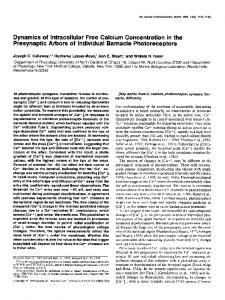
where G;' represents the inertia associated with translational motion of the hand, Gf2 that with rotational motion, and GTz coupling effect of the translation and rotation. The virtual mass was defined as a ratio of the applied force f h and a projection of the hand acceleration v h onto the force direction, i.e.
RbTMbR;'
{ ( ) - ( )} = vb
J3dt
(24)
Wb
Wb
where indicates velocity after the collision. Provided that the'non-linear force 3 I of eq.(20) is small and negligible for the impulsive dynamics, integration of F yields { I }
where n is a unit vector indicating the force direction (see Fig.4). In general, the directions of the applied force does not coincide the yielded acceleration. To separete the discussion on magnitude and direction of the acceleration, we introduce two parameters:
/Fdt=G*-'{(
ov h
)}
(25)
From (24) and (25) we obtain
The equation represents the principle that the momentum before and after the impact remains constant. By means of the inversion of Ex-GIT, G*-', we can get such a simple expression against the complicated chain problem, as a familiar mass points collision theory. In case that the hand grasps the body B rigidly, just as fully plastic impact, the body goes togather with the hand after contact, i.e.,
where k is a unit vector indicating the acceleration direction (see Fig.4). To avoid confusion, we call mp* -"projected" virtual mass and m: -"absolute" virtual mass. The magnitude and direction of the acceleration caused by the impact is discussed in section 6.
5
vi ) - (
Wh
Collision Problem
In this section, the proposed concept of Ex-GIT is applied to a collision problem. Let us suppose the case that a rigid body B with inertia property mt,,Ib
902
Authorized licensed use limited to: TOHOKU UNIVERSITY. Downloaded on April 07,2010 at 04:02:23 EDT from IEEE Xplore. Restrictions apply.
Substitute it into eq.(26), we obtain I(
0.5 ?
+G*-'(
2h) }
Or the case when the body B rebounds from the hand as fully elastic impact, the relative volocities before and after impact are equal, i.e.,
( v i ) - ( '.)=( wb
wh
wh v h ) - (
2)
mass point B (29)
Fig.5 Simulation model
In conjunction with eq.(26), we obtain
By means of eq.(28) or (30),we can predict the motion of hand of the free-floating chain just after the collision, from imformation of the velocity condition before contact and inertia properties G*,RrTMbR;': we need not to use the imformation of impact force F explicitly.
6
0
I
I
I
45
90
135
I 180
(3 (de91
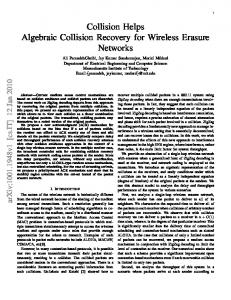
(a) relationship between absolute virtual mass mz and impulse direction B
Simulation
This section presents a pictorial example of collision problem with a simple mathematical model. Suppose that a free-floating chain composed of three uniform rods of 1.0 [m] length and 1.0 [kg] mass, connected with two revolutional joints, makes two dimentional motion on a plain. A mass point coming from a direction 0, as shown in Fig.5, collides at an endpoint of the chain, when the line of mass point velocity agrees with the line of impact. Let us examine the magnitude and direction of the endpoint acceleration caused by the collision, by means of the virtual mass concept. The absolute virtual mass m: defined in (18) represents a reciprocal of the acceleration magnitude, and the angle $ in (19) the acceleration direction. Before the contact the chain stands still with the initial posture as Fig.5. Under this condition, a numerical simulation was executed. The solid line in
50 I
-50
1
0
I
I
I
I
I
45
90
135
180
8( d 4 (b) relationship between acceleration direction and impulse direction B
4
Fig.6 Simulation results
903
Authorized licensed use limited to: TOHOKU UNIVERSITY. Downloaded on April 07,2010 at 04:02:23 EDT from IEEE Xplore. Restrictions apply.
Fig.6 shows the relationship between m:, .II, and impulse direction 8, in case the joints rotate freely ( p = 0 ) . On the other hand, the broken line in Fig.6, in case the joints are fixed firmly ( p = I). The highest peak of the virtual mass curve represents a impulse direction where the lowest acceleration yields, or the chain behaves in the most massive way: that implies the largest impulse force will be generated. For the fixed joint case (broken line), 6 = 5l[deg] is the most massive direction, where the virtual mass is equal to the total mass of the links, 3.0 [kg]. It is very easy to explain this phenomenon because, at this direction, the total mass center of the links lies on the line of impulse, therefore no rotation is caused and the united links behaves as a mass point. At the same time, at 6 = 5l[deg], the directions of the impulse coincides with that of the caused acceleration: i.e. $ =
collision theory. The authors also presented, using a simple mathematical model, the significant difference of the dynamic behaviour at collision among a free joint chain and a united rigid body.
References K.Ninomiya et al: "Numerical Simulation of a Space Manipulator Control for Satellite Retrieval", IEE Symp. on Robot Control, pp.109116, 1988. Z.Vafa, S.Dubowsky: "On the Dynamics of Manipulators in Space Using the Virtual Manipulator Approach", Proc. of 1987 IEEE Int. Cont on Robotics and Automation, pp.579-585,1987. Y.Umetani, K.Yoshida: "Continuous Path Control of Space Manipulator Mounted on OMV", Acta Astronautica, vo1.15, No.12, pp.981-986, 1987.
0.
While, as for the free joint case (solid line), the chain becomes most massive at 8 = 90[deg], where the directions of the impulse and the acceleration agrees. This direction is equal to the line of the endlink, i.e, the endlink on which the impulsive force acts has a dominant effect in free-joint-chain collision problem. The virtual mass at this direction is not equal but much smaller than the total mass of the chain. Because each links make a translational and a rotational motion, we feel lighter. The above examples typically present a difference of the dynamic behaviour at collision, between a free-joint-chain and a united-rigidbody. In addition, dotted lines in the figures show the case half resistance of joints, p = 0.51. In this case, the virtual mass always lies between a free-joint-chain and a united-rigid-body, and the massive peak, zerocross in the $ chart, is between 51 and 90 [deg]. By means of these charts, we can predict the impulsive behaviour of free-floating links with particular, but uneasy to model, joint inertia, friction and elasticity.
7
Y.Umetani, K.Yoshida: "Resolved Motion Rate Control of Space Manipulators with Generalized Jacobian Matrix", IEEE Trans. on Robotics and Automation, vo1.5, No.3, pp.303-314, 1989.
Y .Masut ani, F.Miyazaki, S.Arimoto: "Modeling and Sensory Feedback Control for Space Manipulators", Proc. of NASA Conference on Space Telerobotics, Pasadena, CA, U.S.A. vo1.3, pp.287296, 1989. H.Shimoji, M.Inoue, K.Tsuchiya, et al.: "Simulation System for a Space Robot Using 6 Axis Servos", Proc. of 11th IFAC Symp. on Automatic Control in Aerospace, Tsukuba, Japan, pp.131136, 1989. K.Yamada, K.Tsuchiya: "Force Control of a Space Manipulator", Proc. I-SAIRAS'SO, Kobe, Japan, pp.255-258, 1990. 9 :
H.Asada: "A Geometrical Representation of Manipulator Dynamics and Its Application to Arm Design", ASME J. of Dynamic Systems, Measurement and Control, ~01.105,pp.131-135, 1983.
Conclusion
The authors discussed the basic formulation of collision dynamics for a chain of free-floating rigid-links, with proposing the "Extended Generalized Inertia Tensor (Ex-GIT)", which is an extended version of the GIT for ground-based arms, and the virtual mass concepts based on the Ex-GIT. By means of the concepts, they formulate the collision problem focusing on a velocity relationship just before and after the collision without sensing the impact force, but considereing the momentum conservation law. As a result, they've got such a simple expression against the complicated chain problem, just as a familiar mass points
H.Asada, K.Ogawa: "On the Dynamic Analysis of a Manipulator and Its End Effector Interacing with the Environment", Proc. 1987 IEEE Int. Conf. on Robotics and Automation, pp.751-756, 1987.
904
Authorized licensed use limited to: TOHOKU UNIVERSITY. Downloaded on April 07,2010 at 04:02:23 EDT from IEEE Xplore. Restrictions apply.