1.3.3 A more detailed description of dune forms generated by unimodal ... 3.3
Dynamics of the saltation layer and simplifications for dune modeling . . 38.
Modeling of Dune Morphology
Diplomarbeit
vorgelegt von Veit Schw¨ammle aus Korntal
Hauptberichter: Mitberichter:
Prof. Dr. H. J. Herrmann Dr. F. Assaad
Institut f¨ur Computeranwendungen 1 der Universit¨at Stuttgart 2002
Contents Introduction 1
5
Basics 1.1 Atmospheric boundary layer . . . . . . . . . . . . . . . . . . . . . . . . 1.2 Aeolian sand transport . . . . . . . . . . . . . . . . . . . . . . . . . . . 1.2.1 Sand grain size and transport modes . . . . . . . . . . . . . . . . 1.2.2 Forces and entrainment threshold . . . . . . . . . . . . . . . . . 1.2.3 Saltation . . . . . . . . . . . . . . . . . . . . . . . . . . . . . . 1.3 Dune geomorphology . . . . . . . . . . . . . . . . . . . . . . . . . . . . 1.3.1 Hierarchies . . . . . . . . . . . . . . . . . . . . . . . . . . . . . 1.3.2 Classification and building conditions of simple dunes . . . . . . 1.3.3 A more detailed description of dune forms generated by unimodal wind source . . . . . . . . . . . . . . . . . . . . . . . . . . . . . 1.3.4 Dune fields . . . . . . . . . . . . . . . . . . . . . . . . . . . . .
23 25
2
Air shear stress over heaps and dunes 2.1 Turbulence models . . . . . . . . . . . . . . . . . . . . . . . . . . . . . 2.2 The separation bubble and its justification . . . . . . . . . . . . . . . . . 2.3 An analytical model for the air shear stress . . . . . . . . . . . . . . . . .
27 27 28 30
3
A continuum saltation model 3.1 The model . . . . . . . . . . . . . . . . . . . . . . . . . . . . . . . . 3.1.1 The grain born shear stress . . . . . . . . . . . . . . . . . . . 3.1.2 Erosion and deposition rates . . . . . . . . . . . . . . . . . . 3.1.3 Forces . . . . . . . . . . . . . . . . . . . . . . . . . . . . . . 3.2 The closed model and the saturated sand flux . . . . . . . . . . . . . 3.3 Dynamics of the saltation layer and simplifications for dune modeling
. . . . . .
33 33 34 35 36 36 38
The numerical model for sand dunes 4.1 The complete model . . . . . . . . . . . . . . . . . . . . . . . . . . . . 4.2 The air shear stress τ at the ground . . . . . . . . . . . . . . . . . . . . . 4.3 The sand flux q . . . . . . . . . . . . . . . . . . . . . . . . . . . . . . .
41 41 42 42
4
3
. . . . . .
9 9 10 11 13 15 18 18 19
4
Contents 4.4 4.5 4.6 4.7
Avalanches . . . . . . . . . . . . . . . . . The time evolution of the surface . . . . . . The initial surface and boundary conditions Conclusion . . . . . . . . . . . . . . . . .
. . . .
. . . .
. . . .
. . . .
. . . .
. . . .
. . . .
. . . .
. . . .
. . . .
. . . .
. . . .
. . . .
. . . .
. . . .
. . . .
44 45 45 46
5 Transverse Dunes 5.1 Introduction . . . . . . . . . . . . . . . . . . . . . . . . . . . 5.2 The model of 3-dimensional dunes and translational invariance 5.3 The model of 2-dimensional dunes with constant sand influx . 5.3.1 Time evolution . . . . . . . . . . . . . . . . . . . . . 5.3.2 Dune velocity . . . . . . . . . . . . . . . . . . . . . . 5.4 The model of 2-dimensional dunes with periodic boundary . . 5.4.1 Time evolution . . . . . . . . . . . . . . . . . . . . . 5.4.2 Do transversal dunes behave like solitons? . . . . . . . 5.5 Conclusions . . . . . . . . . . . . . . . . . . . . . . . . . . .
. . . . . . . . .
. . . . . . . . .
. . . . . . . . .
. . . . . . . . .
. . . . . . . . .
. . . . . . . . .
47 47 49 55 55 61 64 64 64 69
6 Barchan dunes 6.1 Introduction . . . . . . . . . . . . . . . . . . . . . 6.2 The role of roughness length and dune size . . . . . 6.3 Scaling laws . . . . . . . . . . . . . . . . . . . . . 6.4 The effect of diffusion . . . . . . . . . . . . . . . 6.5 Barchanoids, between barchan and transverse dunes 6.6 Conclusions . . . . . . . . . . . . . . . . . . . . .
. . . . . .
. . . . . .
. . . . . .
. . . . . .
. . . . . .
. . . . . .
71 71 72 77 84 84 87
. . . . . .
. . . . . .
. . . . . .
. . . . . .
. . . . . .
. . . . . .
7 Conclusion
89
Bibliography
95
Introduction Dune formations can be found in deserts and on coasts all over the world. Every continent contains large areas of sand except the Antarctica. The Sahara is the world’s largest desert with about 7 million square kilometers covering almost one half of the entire African continent. When wind has the strength to move sand grains different kinds of dune forms appear. Even in the Antarctica (Figure 1) special dunes were found composed of snow. Dunes can also be seen in the ocean. This sort of dune formation is quite similar to the
Figure 1: Satellite view of a snow dune field in the Antarctica. (Photo: Ken Jezek, NASA - Goddard Space Flight Center Scientific Visualization Studio)
5
6
Contents
Figure 2: The Mars Viking and Global Surveyor missions revealed the existence of barchan dunes on Mars near the north pole. (Photos: Mars Global Surveyor, 1998/1999)
corresponding one on land although the interaction between fluid (air, water) and sand grains is rather different. Recently barchan dunes have been found even on Mars near the north pole (Figure 2). Mars is surrounded by a less dense atmosphere than Earth. A plain surface that has slack sediment grains from low to high disposal with grain sizes which can be moved by the acting flow matter is unstable. Observations proofed that a large variety of dune forms exists (Finkel 1959; Coursin 1964; Hastenrath 1967; Lettau and Lettau 1969; Sarnthein and Walger 1974; Howard and Morton 1978; J¨akel 1980; Hastenrath 1987; Slattery 1990; Kocurek, Townsley, Yeh, Havholm, and Sweet 1992; Wiggs, Livingstone, and Warren 1996; Hesp and Hastings 1998; Walker 1998; Jimenez, Maia, Serra, and Morais 1999; Sauermann, Rognon, Poliakov, and Herrmann 2000; Sauermann, Andrade, and Herrmann 2001). However, this Diploma thesis will only regard dunes consisting of sand and formed by wind.
Contents
7
In comparison to other geological dynamic processes the topography of dune fields changes rapidly. Generally dunes move about some meters a year carrying large amounts of sand. The local population has to protect itself from this almost irresistibly advancing hazard. Nevertheless there are a lot of attempts to get along with this problem. One method for example is to spend a lot of money on bulldozers in order to carry the sand away from roads, pipelines and houses. In some areas it was helpful to plant vegetation on dunes to retain them from moving further on. Also the construction of fences has been applied. The search for the best method, for example to put up fences at sensitive places of a dune, is difficult to assure over large time periods. An experiment needs years to get useful results. Therefore people made many attempts to understand the processes behind dune formation. Dune scales are too high to make experiments for example in wind tunnels. This is the reason why experiments cannot be made under well predefined conditions to get more knowledge of dynamics and morphology.
When ground is filled up with sand grains and exposed to atmospheric movements, the surface normally changes. Winds move sand grains over various distances. Different conditions, for example changing wind directions, wind strength and grain size lead to the generation of the variety of dune morphologies. On the micro scale exists a complex physics describing the interaction between air, sand and sand bed. Wind tunnel experiments help to get more knowledge about wind field and sediment transport (Rasmussen and Mikkelsen 1991; White and Mounla 1991; Nalpanis, Hunt, and Barrett 1993; Wiggs, Livingstone, and Warren 1996; Nishimura and Hunt 2000). Phenomenological relations for the sand flux in saltation were published (Bagnold 1936; Bagnold 1941; Owen 1964; Lettau and Lettau 1978; Sørensen 1991; Sauermann, Kroy, and Herrmann 2001a). Numerical simulations of the dynamics of the saltation layer helped to understand more about sand transport (Anderson and Haff 1988; Anderson 1991; McEwan and Willetts 1991). Finally, numerical simulations of dune formation in two and three dimensions, which will be the topic in this thesis, gave interesting results (Wippermann and Gross 1986; Zeman and Jensen 1988; Fisher and Galdies 1988; Stam 1997; Nishimori, Yamasaki, and Andersen 1999; van Boxel, Arens, and van Dijk 1999; van Dijk, Arens, and van Boxel 1999; Herrmann and Sauermann 2000; Kroy, Sauermann, and Herrmann 2001). Recently also an analytical work was published (Andreotti and Claudin 2002).
In this thesis the theory of the mechanisms involved in dune formation will be discussed. The wind field over the dune, the aeolian sand transport will be described and algorithms to calculate them will be introduced. From these a dune model will be derived. The results of the dune model for barchan and transverse dunes will be presented.
8
Contents
Overview In Chapter 1 the general physics involved in dune formation is described. Insight into the physics of the atmospheric boundary layer (turbulent logarithmic profile), the different modes of aeolian sediment transport and their phenomenological sand flux relations is given in the first two sections. A section of dune geomorphology introduces dune types with respect to their external parameters and dune fields. Further insight into dunes generated by an unimodal wind source concludes the chapter. Chapter 2 starts giving a short survey over turbulence models. The separation of the air flow over a dune with a sharp brink justifies the concept of a separation bubble. With this concept a smooth surface is used to calculate the shear stress with an analytical formula based on a linear perturbation theory. With this approach the shear stress over dunes can be calculated more efficiently. In Chapter 3 a continuum model of saltation transport is introduced. Expressions for the grain born shear stress, the source term comprising the erosion and deposition of sand from the ground and the forces acting on the grains are derived. This finally leads to a closed model which describes the saltation transport of grains including time transients and states out of equilibrium. The results of the model for saturated sand flux are depicted. Finally the calculated dynamics of the model justifies some simplifications of the model which decouple the equations to get a faster algorithm. In Chapter 4 the entire dune model is described. Shortly the different parts of the model are resumed. The shear stress over the dunes is calculated according to Chapter 2 and the sand flux follows the saltation model in Chapter 3. Additionally the model contains calculations of the avalanches and time evolution of the dune surface. Different external parameters of the model can yield to various solutions due to different boundary conditions and initial surfaces. In Chapter 5 simulations of 3-dimensional transverse dunes lead to the assumption that the system tries to reach translational invariance. The modeling of 2-dimensional dune fields with open boundary reveals potential laws for the time evolution and dune velocity. Simulations of 2-dimensional dune fields with periodic boundary show the same properties. The wandering of a small dune over a bigger one is discussed. In Chapter 6 the results of barchan dune simulations with respect to different parameters of the shear stress calculation are compared to measurements. The scaling laws of modeled barchan dunes are compared with the data of other models and measurements. The effect of an additional diffusion term is examined. Finally the simulations of barchanoid dunes are presented.
Chapter 1 Basics In this chapter the physics which drives the dynamics of desert dunes will be discussed. An introduction to the main quantities and features will be given. First the flow of air in the atmospheric boundary layer will be explained. The aim is to get an expression for the shear stress of the air acting on the sand. In the second section different sand transports by air movement are explained giving a more precise description of saltation. The third section introduces dune types which are found in deserts. After that a further insight will be given into dunes formed by an unidirectional wind force. The last section tries to give a small survey over the dynamics in dune fields.
1.1
Atmospheric boundary layer
To maintain the steady movement of dunes there has to be a source which carries the energy to move sand over the surface. The shear stress of the air flow in the atmospheric boundary layer can force sediments to be entrained. At first it is important to know if the flow over dunes is situated in a laminar or a turbulent regime. The Reynolds Re number gives a good estimate. It consists of the ratio between inertial and viscous force: Re =
ρv 2 /L Lv = , 2 µv/L ν
(1.1)
where ρ denotes the density of the fluid, L a characteristic length, v a characteristic wind velocity, µ the viscosity of the fluid and ν = µ/ρ the kinematic viscosity. If the inertial force dominates the viscous force the regime gets turbulent and the Reynolds number becomes greater than 1. The scaling of the objects which will be discussed is normally that of the height of a dune. The calculation leads to a high Reynolds number of about 6000 (Houghton 1986). Hence, even small wind speeds create turbulent flows. Turbulent flow means randomly directed and distributed fluctuations and eddies. The shear stresses 9
10
1.2 Aeolian sand transport A)
B)
Figure 1.1: a) Small grains are immersed in the laminar sub-layer which creates an aerodynamically smooth surface. b) Grains larger than the laminar sub-layer are isolated objects and create an aerodynamically rough surface.
of turbulent flow are much higher than of laminar flow. According to the mixing length theory (Prandtl 1935) turbulent shear stress can be expressed by � �2 dv dv 2 = ρl , (1.2) τT = η dz dz where η is turbulent viscosity and l the mixing length. At fully turbulent flows the dynamic viscosity µ gets much smaller than the turbulent viscosity η. Thus the former viscosity can be neglected. Under the assumption that the mixing length increases linearly with the distance from the surface (l = κz, κ ≈ 0.4 is the von K´arm´an universal constant for turbulent flow) integration from z0 to z of Equation 1.2 yields the widely used logarithmic profile of the atmospheric boundary layer: v(z) =
u∗ z ln . κ z0
(1.3)
z0 has the meaning of a roughness length. This is either the thickness of the laminar sub-layer for aerodynamically smooth surfaces or the p size of surface perturbations for aerodynamically rough surfaces (Figure 1.1). u∗ = τ /ρ is called shear stress velocity. Although it has the dimension of a velocity the shear velocity u∗ anyhow is used as a measure for the shear stress.
1.2 Aeolian sand transport Different kinds of sand transport modes by wind are explained in this section. Sand gets eroded and deposited. Particularly the saltation transport most interesting for the dune
Basics
11
formation will be described. On the microscopic scale forces act on the sand grains. The corresponding phenomenological relations for the macroscopic scale which hold for the saturated saltation will be defined.
1.2.1
Sand grain size and transport modes
The main properties of sand are grain diameter d, shape and the material of which the grains consist. Diameter Classification ranges from large sand grain diameter (d = 2 mm) to small diameter (d ≈ 0.063 mm) (Friedman and Sanders 1978). They are called coarse and fine sand respectively. Shape Since nature almost always produces very complex things sand grains are composed of a big variety of shapes. According to Pye and Tsoar (1990) it is classified into “well rounded”, “angular”, “platy”, “elongated”, or “compact”. Material Mostly sand grains consist of quartz (SiO2 ) which has a density of ρquartz = 2650 kg m−3 . After Pye and Tsoar (1990) sand grains of dune fields have a sharply peaked distribution with an average diameter of about 0.2 to 0.25 mm. The form of sand transport depends on different parameters. Main parameters are shear velocity and the weight of the sand grains. Weight can be expressed by the diameter assuming the same density. A good measure to distinguish between transport mechanisms is given according to the degree of detachment of the grains from the ground. Bagnold (1941) proposed three distinct types of sand transport induced by wind: creep The sand grains roll and slide along the surface. During this movement they stay in contact with the surface saltation The sand grains jump short distances. The range is some centimeters. The entrainment, i.e. lifting of the grains originates in the shear stress of the air flow or in the impact of other sand grains descending again to the surface. Impacting sand grains transported by saltation sometimes cannot reach sufficient velocity to enter into a new ballistic jump. So they are moving much shorter distances. This process is called reptation. suspension The turbulent irregular movement of the atmospheric layer is strong enough to keep the sand grains aloft. They are transported over long distances.
12
1.2 Aeolian sand transport
n sp su d ifie lta
tio
m
n
od
0.1
sa
0.05
typical wind speeds and dune sand
en
sio
sio n en
0.2
su sp
shear velocity [m/s]
0.5
PSfrag replacements
0.02 0.01 0.01
wf u∗
= 0.1
0.02
wf u∗
0.05
=1 0.1
0.2
0.5
grain diameter [mm] Figure 1.2: The mechanism of transport depends on the shear velocity of the air and the grain diameter. For typical dune sand (0.2 mm < d < 0.3 mm) and wind velocities (0.2 m s−1 < u∗ < 0.6 m s−1 ) on Earth, aeolian sand transport occurs by saltation (area inside the rectangle).
The latter three transport mechanisms are summarized by calling them bed-load. A good measure for the vertical component of the turbulent shear stress is given by the shear velocity (Lumley and Panofsky 1964; Bagnold 1973; Pasquill 1974). The ratio between settling velocity wf and shear velocity helps to distinguish suspension and bed-load. The demarkation line wf /u∗ = 1 is used to decide between the two processes. Thus wf /u∗ � 1 and wf /u∗ � 1 define suspension and bed-load respectively (Pye and Tsoar 1990). For small grains within the range of 0.001–0.05 mm the settling velocity is expressed by (Green and Lane 1964),
wf =
ρquartz g 2 d = K d2 , 18µ
(1.4)
where K = 8.1 106 m−1 s−1 . Shear velocities in the range of 0.18 to 0.6 m s−1 are sufficiently strong to keep the trajectories of the sand grains of this diameter range within the definition of suspension. Hence, sand grains of dunes with a typical diameter of 0.25 mm mainly move by bed-load and thereby saltation (Figure 1.2). That is the reason why in our models only saltation transport is considered.
Basics
13
Fl
Fd φ
PSfrag replacements
p
Fg
Figure 1.3: The grain starts to role when the drag and lift force exceed the gravitational force. This can be expressed by a momentum balance with respect to the pivot point p.
1.2.2
Forces and entrainment threshold
The forces of the air flow acting on a single sand grain are estimated here. They can be divided into the two directions parallel and perpendicular to the surface. In Figure 1.3 also flow lines and the velocity profile are depicted. The parallel force called drag force Fd points in the direction of the air flow. A turbulent atmospheric layer yields a force which scales quadratic with velocity, the so called Newton’s turbulent drag, Fd = βρu2∗
πd2 , 4
(1.5)
where β is a phenomenological parameter that includes some characteristics of the bed such as its packing. The other force of the air flow originates from the pressure difference ∆p between bottom and top of the sand grain. The strong velocity gradient of wind speed leads to this pressure difference. The resulting force is called lift force Fl : Fl = ∆p
πd2 πd2 = CL ρU 2 , 4 2
(1.6)
where CL = 0.0624 (Chepil 1958). U denotes the air velocity at a height of 0.35d with respect to the zero level at z0 . Chepil (1958) showed furthermore that the ratio c = 0.85 between the forces of drag and lift is constant within the designated range of Reynolds numbers, (1.7) Fl = c Fd .
14
1.2 Aeolian sand transport
As the force opposed to Fl gravity has to be introduced. The sand grain is approximated to be a sphere, so that πd3 . (1.8) Fg = ρ0 g 6 The purpose of this section is to get an equation for the threshold of entrainment, i.e. the minimum shear stress of wind at which it will be able to lift a sand grain from the surface. Therefore the momentum balance of rotating the upper sand grain around its touching point p (Figure 1.3) can be expressed as d d Fd cos φ = (Fg − Fl ) sin φ. 2 2
(1.9)
φ is the angle between vertical direction and the line pointing from the sand grain center to p. By inserting (1.5), (1.7), and (1.8) this finally leads to the so called fluid threshold or aerodynamic entrainment threshold τta � � τta 2 sin φ = . (1.10) ρ0 gd 3 β cos φ + c sin φ So the parameters of the threshold, the grain diameter d and the immersed density ρ0 , are directly proportional to the shear stress. The angle φ can be interpreted as a parameter of the packing of the grains. β is determined by shape and sorting. Shields (1936) named the right hand side of Equation (1.10) a dimensionless coefficient Θ (Shields parameter). It ranges from 0.01 to 0.014 for high Reynolds p numbers. Hence, τ /ρair , then Equawhen using the expression for the shear velocity equation u∗ = tion (1.10) defines the fluid threshold shear velocity u∗ta , s ρ0 gd (1.11) u∗ta = Θ . ρair The derivation of this paragraph holds only for sand grains which have a diameter that is large enough to neglect cohesive and repulsive forces between the grains. This is valid for a diameter larger than 0.2 mm. Inserting typical values into Equation (1.11), u∗ta is reaching a shear velocity of u∗ta = 0.25 ms−1 . Nevertheless this value is valid only for entrainment of sand grains into air. When there are already grains entrained, i.e the air flow is transporting sand, then an impacting sand grain gives large momentum transfer to a resting grain on the bed. Thus the threshold value gets lower. It is called impact threshold u∗t (Bagnold 1937). Still the expression of Equation (1.11) keeps valid but with the modification of an effective Shields parameter Θ = 0.0064. In the turbulent wind regimes over dune surfaces fluctuations can determine shear velocities which exceed the entrainment threshold. That is why sand transport can be maintained for shear velocities between u∗ta and u∗t . Consequently impact threshold gets the important value for aeolian transport. Of course these calculations of a single threshold are getting difficult for poorly sorted
Basics
15
sediments. Moisture and cementing neither have been included. On the other side the threshold is changing at inclined surfaces. Gravity directs into another direction. This effect should be included in the momentum balance (1.9). Pye and Tsoar (1990) made a more detailed discussion of these effects.
1.2.3
Saltation
When there are enough grains impacting onto the sand bed direct aerodynamic entrainment gets negligible. The process of the collision of sand grains entraining other grains is called splash process. Theoretical and experimental investigation has been made recently (Nalpanis, Hunt, and Barrett 1993; Rioual, Valance, and Bideau 2000). As grains attain momentum by the drag force of the air flow this flow is decelerated. This process is called feedback process. After some time and with sufficient sand supply saltation reaches an equilibrium transport rate called saturation. Direct aerodynamic entrainment As it was explained in the previous section sand grains are entrained directly from the sand bed for a shear stress higher than the fluid threshold shear stress τta . The linear model of Anderson (1991) proposes the number of entrained grains proportional to excess shear stress, (1.12) Na = ζ(τ − τta ), where Na is the number of entrained grains per time and ζ a proportionality constant of about 105 grains N−1 s−1 . The direct entrainment gets important to begin the chain reaction leading to saltation like for example at places where the sand bed begins, i.e. where downwind no sand supply is available. The saltation trajectory Entrained grains in the air stream are exposed to the following forces. Aerodynamic forces lift and drag a sand grain. The gravitational force Fg obviously lets the trajectory end on the surface again. The drag force Fd accelerates in the horizontal direction, 1 πd2 (v(z) − u) |v(z) − u| , Fd = ρair Cd 2 4
(1.13)
where d is the grain diameter, v(z) the velocity of the air, u the velocity of the grain, and Cd the drag coefficient that depends on the local Reynolds number Re = |v − u|d/ν. The lift force has remarkable effects only a few grain diameters away from ground (Anderson and Hallet 1986). Thus it is convenient to include the effects of the lift force in the initial
16
1.2 Aeolian sand transport
velocity of the grain. During its movement within the trajectory the lift force is neglected. Turbulent fluctuations in time and space are not taken in account. Hence, the trajectory can be calculated by the second law of Newton, dx = u; dt
du 1 = (Fg + Fd ) , dt m
(1.14)
where the gravitational force is Fg = mg with m is the mass of the grain and g is the gravitational acceleration. As initial conditions the initial position and velocity u0 are introduced. Thus flight time and maximal height of the grain trajectory are given by T =
2uz0 ; g
h=
u2z0 , 2g
(1.15)
where uz0 denotes the vertical component of the initial velocity. From a more detailed estimate it results that this simple calculation has an error of about 10–20% (Anderson and Hallet 1986; Sørensen 1991). Finally there are presented some values of measurements in a wind tunnel: for a shear velocity of u∗ = 0.5 m s−1 Nalpanis, Hunt, and Barrett (1993) obtained a flight time T ≈ 0.08 s, hop height h ≈ 3.8 cm and hop length l ≈ 45 cm. The splash process The reaction of the sand bed to the impact of a sand grain is of rather complex nature. The splash process comprises the interaction between the sand grain and the grains in the vicinity of the impact. Thus many grains can be involved in this process. Numerical and experimental studies have been made by Anderson (1991, Rioual, Valance, and Bideau (2000). Mainly the splash process is described in a stochastic way. It is divided into the following three different resulting situations: First the incoming sand grain distributes its momentum to the sand bed so that no other grain gains sufficient energy to leave the ground. Secondly, the grain rebounces loosing some of its energy. Thirdly, the incoming grain distributes its energy so that one or more grains can leave the bed. The splash process is described by the splash function S(ui , φi , θi ; ue , φe , θe ). It defines the probability to dislodge a grain with a certain angle φe , θe and velocity ue due to an impacting grain with an angle φi , θi and velocity ui . Regarding the angles θ to be the angles determining horizontal directions they vary only due to lateral diffusion. That means that they result to zero in average. For the saltation transport here described it is found an impact angle with respect to the sand bed from 10o to 15o . The feedback process There are two possibilities to calculate the momentum transfer from the air to the grains. The first is to add a body force f to the right side of the Naiver Stokes equation. f means
Basics
17
an average momentum transfer from the air to the grains, ρair ∂t v + ρair (v∇)v = −∇p + ∇τ + f
(1.16)
Here, ρair denotes the density, v the velocity, p the pressure, and τ the shear stress of the air. This was used by Anderson (1991). The other approach (Owen 1964) divides the overall air shear stress into a grain born and an air born part. The air born shear stress is used to determine the velocity profile. Sauermann, Kroy, and Herrmann (2001b) used this approach for their model of saltation transport. The dune model described in Chapter 4 also contains these relations. Due to the rising momentum transfer from the air to the grains for a larger amount of grains in air the air born shear stress drops. That means that the system reaches a steady state. Thus the number of grains in air is limited. Sand transport rate Different approaches to describe saltation in a macroscopic way have been made. They are not directly connected with the microscopic processes explained before. Macroscopic variable is the sand flux q which means the sand flux per unit width and time. This sand flux depends on the shear velocity u∗ , the threshold u∗t , the grain diameter d and others. In the following relations history and transients out of non-equilibrium conditions are not considered. Hence, they describe the equilibrium state where the sand flux is saturated. Measurements in wind tunnels showed that for shear velocities u∗ � u∗t the sand flux scales with the cube of the shear velocity (q ∝ u3∗ ) (Butterfield 1993; Rasmussen and Mikkelsen 1991). Near the shear threshold the situation seems to be much more complicated. Still there are differences between empirical and theoretical flux predictions. The first relation proposing the cubic proportionality is (Bagnold 1941), r ρair d 3 u, (1.17) qB = CB g D ∗ where d is the grain diameter and D = 250 µm a reference grain diameter. To include the fact that under a certain threshold the shear stress is not strong enough to keep saltation transport many other phenomenological sand flux relations have been made. The mostly used expression was mentioned by Lettau and Lettau (1978), ρair (1.18) qL = CL u2∗ (u∗ − u∗t ) g where CL is a fit parameter. Other attempts to average the microscopic processes contained more information about aeolian sand transport (Owen 1964; Ungar and Haff 1987; Sørensen 1985; Werner 1990).
18
1.3 Dune geomorphology
Sørensen (1991) calculated the following relation, where CS is an analytically determined parameter, ρair u∗ (u∗ − u∗t )(u∗ + 7.6 ∗ u∗t + 2.05 m s−1 ). (1.19) qS = CS g Although experimental data is reproduced quite well with this functional structure the parameter CS is four times to small. One additionally is interested in the way how the system behaves in non-equilibrium states which still have not reached the saturation state. Numerical simulations on the grain scale by Anderson and Haff (1988, Anderson (1991, McEwan and Willetts (1991) showed that the system needs about two seconds to reach the equilibrium state for a flat surface. This matches quite well with experimental data by wind tunnel measurements (Butterfield 1993). A macroscopic continuum saltation model was proposed recently that includes saturation transients (Sauermann, Kroy, and Herrmann (2001b) and Chapter 3).
1.3 Dune geomorphology In this section the aeolian geomorphology of sand sediments is explained. First the different hierarchies of surface patterns are introduced. Different length scales yield various types of sand formation. Secondly the dune types appearing for different parameters are discussed. A more detailed overview of sand dunes with an unidirectional wind source are given. Finally the dynamics of whole dune fields is shortly discussed.
1.3.1
Hierarchies
According to Wilson (1972, Cooke, Warren, and Goudie (1993) dune fields show hierarchical structures. Wilson (1972) divided them into three groups of classification with respect to their length scale. They are called ripples, dunes and draas with a typical wave length of 10−2 – 10−1 , 101 – 102 and 102 – 103 meters, respectively. Ripples grow on the most bare sand surfaces which means that they also grow on dunes. The wavelength of ripples is not related to the saltation length. Instead it is related to the mean reptation length (Anderson 1987). For an explanation of saltation and reptation see the Section 1.2.3 of this chapter. Dunes and draas are governed by the saturation length which determines a minimum dune size (Pascal, Douady, and Andreotti 2002). Wilson (1972) supposed that all three hierarchical structures co-exist in quasi-equilibrium but none of them can grow into another. The other explanation of the superimposition of these structure proposes that dunes and draas co-exist due to different wind regimes (Figure 1.4). In this thesis dunes and draas are considered equally.
Basics
19
Figure 1.4: Dune type diagram with regard to sand availability and wind direction variability (after Livingstone and Warren (1996))
A further discussion is given in Chapter 5. The formation of sand ripples is not investigated here because of the much smaller length scale and the different dynamics.
1.3.2
Classification and building conditions of simple dunes
The main parameters to differentiate between the types of dunes is the sand availability and the change of wind direction. Dunes additionally are classified in free dunes and
20
1.3 Dune geomorphology
Figure 1.5: Schematic views of typical dunes: ( (a)–(e) after Ritter (1995) (f) after NASA (1986) ) anchored dunes. Anchored dunes cannot move because vegetation grows on them or the topography stops them from moving. Free dunes can move freely and their shape can change depending on actual wind speed and wind direction. Although the model used in this thesis can be extended to get more knowledge about anchored dunes the discussion will be mainly on free dunes. One type of an anchored dune, the so called parabolic dune, is shown in Figure 1.5. The arrow denotes the wind direction. The arms of this type are fixed by the growth of plants. Free dunes are classified in three groups depending on the alignment of their crest to the net sand transport. Most dunes consist of a windward side and a slip face. At the wind-
Basics
21
Figure 1.6: Satellite photo of a coastal region of the Namib desert, Namibia (photo from NASA (1986)). Many different dune types can be seen. A description of the dune types in this area is given in Figure 1.7.
Figure 1.7: Map of a coastal region presented in Figure 1.6 (map from NASA (1986)). It describes the different dune type areas
ward side aeolian sand transport processes move the sand grains. The slip face mainly gets changed by down going avalanches. The slope of the slip face of a dune is near to the angle of repose.
22
1.3 Dune geomorphology
Transverse dunes Net sand transport is mainly directed perpendicular to the crest line of these dunes. Transverse dunes are found in wind regimes which are unidirectional. Dome dune Isolated small dunes without a slip face. Barchan dune This isolated dune type is situated in areas of poor sand supply. Their form remind of the half moon. A more detailed description is given in Section 1.3.3. See also Figure 1.5. Transverse dune This dune, also called crescentic dune, corresponds to the barchan with the difference of large sand supply and availability. The crest aligns perpendicular to the net sand transport. Ideal transverse dunes are thought to be symmetric in the direction perpendicular to the wind direction (Figure 1.5). Barchanoids At areas of sand supply which is not sufficient to build transverse dunes and which consists of too much sand for formation of isolated and disconnected barchan dunes the latter get connected (Figure 1.5). Reversing dunes Transverse dunes situated in a wind regime with changes of 180o of the direction. Thus the dune reverses in this time. Linear dunes Linear dunes usually appear in regions where two main wind directions occur. Figure 1.5 also shows that the crests are directed parallel to the mean wind direction. Star dunes Finally for a diverse distribution of wind directions these most complex dune patterns can be found. Star dune Star dunes are large pyramidal dunes with some arms. These arms can have slip faces or not (Figure 1.5). Network dunes This kind of dunes consists of a superposition of transverse dunes which move in different directions. Figure 1.4 gives an overview over the distribution of the different dune forms due to wind directions and sand availability. In the Namib desert in Namibia some of the before described dune types can be found (Figures 1.6, 1.7, 1.8 and 1.9).
Basics
23
Figure 1.8: Satellite photo of crescentic transverse dunes at the coast line of the Namib desert, Namibia (photo from NASA (1986)).
Figure 1.9: Satellite photo of a star dune in the Namib desert, Namibia (photo from NASA (1986)).
1.3.3
A more detailed description of dune forms generated by unimodal wind source
The main dune forms generated by an unimodal wind source are the Barchan dune and the transverse dune. The model which is discussed in this thesis so far is restricted to
24
1.3 Dune geomorphology
Figure 1.10: Satellite view of a field of longitudinal dunes (photo from NASA) unimodal winds. Both move in wind direction where the slip face slows the dune speed down by trapping the sand going over the brink. A description of the different parts of a Barchan dune is given in Figure 1.11. The sand grains at the windward side are entrained and deposited by the shear stress of the wind flow over the dune. Thus the sand grains move over the brink where they get trapped in the slip face. The brink which for big dunes coincides with the crest consists of a sharp edge where the slope changes to the angle of repose. At the slip face the shear stress of the wind is not strong enough to entrain and transport many sand grains. Hence, the process can be described as a relaxing of the surface by avalanches. The avalanches keep the angle of repose of the slip face which is normally about 34o . The migration velocity can be calculated from the sand flux q at the brink and the height h of the brink. Figure 1.11 illustrates the cross-section of either a barchan or a transverse dune in wind direction. For a shape invariant dune that moves with a constant velocity vd the convection equation can be applied, ∂h ∂h = vd , ∂t ∂x
(1.20)
where h(x, t) is the height profile of the dune. The temporal change of the surface is calculated by the local change of the sand flux. Therefore mass conservation leads to ∂h 1 ∂q = , ∂t ρsand ∂x
(1.21)
where ∂q/∂x is the erosion rate. Putting equation (1.21) into (1.20) an expression for the
Basics
25
windward side H
Wb brink
PSfrag replacements wind direction
slip face horns
L0
Ls
Wa
La Lb
crest windward side
brink slip face
Figure 1.11: Sketch of a barchan dune.
dependency of the dune velocity with respect to the dune height is obtained, vd (h) =
1 dq . ρsand dh
(1.22)
This equation also is quite useful to examine if the dune reached a steady state or not. For a height profile which holds no shape invariance following equation is not valid, dq = constant. dh
1.3.4
(1.23)
Dune fields
Mostly deserts present wide areas of ground filled up with large amounts of mobile sand grains. From the huge Sahara desert to smaller areas like Jericoacoara near to Fortaleza in the north of Brazil sometimes various dune types are found in the same area. In section before the Namib sand sea shows a large field with different dune types due to the slightly varying conditions. Even single dunes depend strongly on their surrounding topography.
26
1.3 Dune geomorphology dx = vd dt q
Sfrag replacements h
Figure 1.12: Sketch of the displacement of a dune. The deposition of the volume of sand h dx = q dt/ρsand causes the dune to advance by dx = vd dt.
That is for example the sand supply, mountains, the sea and so on. It is important to consider the entire particular region. The dynamics of a single dune gets influenced by other dunes surrounding them. The steady state presumes for example a long sustained constant influx of sand which is not given in dune fields where the topography is changing rapidly. For example barchan dunes feel other barchans even over large distance by having asymmetries of their shape ((Cooke, Warren, and Goudie 1993)).
Chapter 2 Air shear stress over heaps and dunes In this chapter an algorithm to calculate the shear stress over a two- or three-dimensional hill or dune will be introduced. A short overview of turbulence models will give an insight in the different calculations of wind velocities and shear stresses. In the next section roughly an analytical perturbation theory which supplies a fast algorithm in order to calculate the shear stress over smooth hills will be described. The final section will explain the concept of a separation bubble.
2.1
Turbulence models
Turbulent flows consist of irregularly fluctuating velocity fields. Spatial and temporal fluctuations mix quantities such as the energy and momentum carried by them. The distribution of these fluctuations extends over many scales of time and space so that the simulations of them get computionally too expensive. To obtain reasonable results for practical applications the Navier-Stokes equations have to be averaged to get rid of the small scale dynamics. There is time-averaging, ensemble-averaging and the usage of other modifications of the Navier-Stokes equation to solve the air flow computionally less expensively. But the averaging of something unknown like the small scale fluctuations leads to additional new unknown terms. The relation of these terms to averaged variables is called turbulence model. Turbulence models are based on two common methods which are named Reynolds averaging and filtering. The interest in this thesis is restricted to Reynolds averaging. Therefore the variables of the Navier-Stokes equations are decomposed into a mean and a fluctuating part. That means for the components of the velocity ui = u¯i + u0i , 27
(2.1)
28
2.2 The separation bubble and its justification
and for the other scalar quantities φ = φ¯ + φ0 ,
(2.2)
where u¯i , φ¯ and u0i , φ0 are the mean and fluctuating parts, respectively. φ denotes for example pressure ρ or energy. After substituting Equation (2.1) and (2.2) into the NavierStokes equations and taking a time or ensemble average it is obtained ∂ ∂ρ + (ρu) = 0 ∂t ∂xi � � �� � Dui ∂p ∂ ∂ui ∂uj 2 ∂ul ∂ −ρu0i u0j , ρ =− + µ + − δij + Dt ∂xi ∂xi ∂xj ∂xi 3 ∂xl ∂xi
(2.3)
(2.4)
where the bars on the mean velocity are omitted. Equations 2.3 and 2.4 are called Reynolds–averaged Navier-Stokes equations. Their only difference to the outgoing� Navier-Stokes equations are the additional terms of the Reynolds stresses ∂x∂ i −ρu0i u0j which have to be modeled in order to close (2.4). A relation of these to the mean velocity gradients comprises the Boussinesq hypothesis (Hinze 1975), � � � � ∂u ∂u 2 ρk + µ ∂u i j t i (2.5) −ρu0i u0j = µt + − δij ∂xj ∂xi 3 ∂xi where k is the kinetic energy and µt the turbulent viscosity. The Boussinesq hypothesis contains the small inconsistency that µt is assumed to be isotropic and scalar which is not strictly true. k and µt can be calculated for example with the semi-empirical k-� model of Launder and Spalding (1972). There the turbulent kinetic energy k and the turbulence dissipation rate � are calculated by two differential equations. The turbulent viscosity finally is obtained by k2 µt = ρCµ (2.6) � where Cµ = 0.09 is a constant, determined by experiments with air and water.
2.2 The separation bubble and its justification It was shown in Sauermann (2001) that there appears a large eddy in the lee side after the sharp brink of a dune. A separation of the quasi-laminar flow which is also found at the windward side and the turbulent eddy holds over a long distance after the brink (Figure 2.1). The separation streamline reaches from the point of flow separation (the brink) to the point of re-attachment at a distance of approximately six times the height of the brink. The surface formed by the separation streamlines is called separation bubble s(x). According to Zeman and Jensen (1988) the air shear stress τ (x, y) on the windward side of the dune can be calculated using the envelope that comprises the dune and the
Air shear stress over heaps and dunes
29
Figure 2.1: Sketch of the central slice of a barchan dune and the attached separation bubble. The envelope of both is used to calculate the shear stress τ on the windward side of the dune. 2.5
h(x) s(x) τ (x)
h/H and τ /τ0
2
PSfrag replacements
1.5 1 0.5 0 −3
−2.5
−2
−1.5
−1
−0.5
0
0.5
1
1.5
2
x/L ˜ Figure 2.2: The envelope h(x) of the windward profile of a dune h(x) and the separating streamline s(x) form together a smooth object which is used to calculate the air shear stress τ (x) on the windward side. In the region of re–circulation the air shear stress τ is set to zero.
separation bubble. Measurements of the shear stress over a barchan dune matched quite well with this proposal. This facilitates pretty well the search for a computionally sparse algorithm. A discontinuity like the sharp brink of a dune would make the calculation of the shear stress quite complex. Hence, the shear stress over the dune is not computed over the height profile h(x) of the dune but of the envelope surface, ˜ y) = max (h(x, y), s(x, y)) . h(x,
(2.7)
The other argument to use the concept of the separation bubble comes from the observations made by Sauermann (2001) in Morocco and Brazil. Measurements performed on
30
2.3 An analytical model for the air shear stress
barchan dunes showed that between the horns of a barchan only a negligible amount of sediment transport occurs. That means that the shear stress τ (x, y) in the separation bubble can be set to zero. Figure 2.2 depicts the shear stress approximation in the separation bubble. ˜ y) is used for the calculation of the air shear stress over Hence, the envelope surface h(x, a dune. The functional form for a separation bubble is obtained by the minimal heuristic ansatz of a polynomial of third order. Therefore the dune surface is cut into slides in the wind direction where every slide has its own separation streamline s(x). The condition of smoothness determines already three parameters of the polynomial as the height of the brink s(0) = h0 , the windward slope at the brink has to coincide with the separation streamline’s first point s0 (0) = h00 and the height and slope are zero at the reattachment point s(Lr ) = 0, s0 (Lr ) = 0 (assuming that the separation streamline ends on the ground), i.e. s(x) = a3 x3 + a2 x2 + h00 x + h0 , a3 = (2h0 + h00 Lr ) L−3 r , 0 a2 = − (3h0 + 2h0 Lr ) L−2 r .
(2.8)
The downwind distance Lr is determined by phenomenological observations. According to (Sauermann 2001) a good estimate is given by setting the maximum slope of the separation streamline equal to C = 0.25 (14◦ ). A second-order approximation yields finally the equation for the length of the separation streamline, � �2 ! 3h0 1 h00 1 h00 Lr = 1+ + . (2.9) 2C 4C 8 C For simulations of dune fields and of dunes which localize on a filled sand bed the separation streamlines do not connect smoothly to the height profile but intersect the surface at a distance smaller than Lr after the brink. The height h1 and the slope h01 at the intersection point at x = x1 = x0 + L now substitute the parameters s(Lr ) = 0 and s0 (Lr ) = 0, respectively. Hence, the new separation streamline is calculated according to sn (x) = a3 x3 + a2 x2 + h00 x + h0 , a2 = (3h1 − h01 x1 − 2h00 x1 − 3h0 ) L−2 , a3 = (h01 L − 2h1 + h00 L + 2h0 ) L−3 .
(2.10)
The two separation streamlines are depicted in Figure 2.2.
2.3 An analytical model for the air shear stress Using the concept of the separation bubble the shear stress of the wind over a dune can be calculated with an algorithm which is valid for smooth surfaces. Due to the fact that in
Air shear stress over heaps and dunes
31
Figure 2.3: When the separation streamline s(x) crosses the surface at h(x) 6= 0 the intersection is used to calculate the new separation streamline sn (x).
the model of this thesis the time evolution of dune forms is considered the overall shear stress has to be calculated for every iteration. This computional quite expensive feature needs a fast algorithm. A smooth hill or the envelope of a dune can be considered as a perturbation of the surface that causes a perturbation of the air flow onto the plain. As a basis is used the logarithmic profile of the atmospheric boundary layer over plain ground (Chapter 1). An analytical calculation of the shear stress perturbation onto a two dimensional hill has been performed by Jackson and Hunt (1975). Later, the work has been extended to three dimensional hills and further refined (Sykes 1980; Zeman and Jensen 1988; Carruthers and Hunt 1990; Weng, Hunt, Carruthers, Warren, Wiggs, Livingstone, and Castro 1991). These models are approximations for smooth hills with the criteria that H/L � 1 and 0 < ln−1 (l/z0 ) � 1 where H and L are the height and the half length at half heights, respectively. z0 and l denote the roughness length and the height of the so called shear stress layer of the inner region. According to the work of Hunt, Leibovich, and Richards (1988) the atmospheric boundary layer is divided in four regions which are combined into two, i.e. an inner and an outer region (cf. Figure 2.4). The different physical processes determine different solutions for each layer. These solutions are matched together afterwards. In order to determine the shear stress which is responsible for the sand transport it has to
32
2.3 An analytical model for the air shear stress
Figure 2.4: Sketch of the different regions and layers of the flow used in the calculation of HLR: Upper layer (U), Middle layer (M), shear stress layer (SS), and Inner surface layer (IS).
be calculated close to the surface. Thus the most suitable layer for this purpose should be the shear stress layer. Weng, Hunt, Carruthers, Warren, Wiggs, Livingstone, and Castro (1991) obtained the following shear stress perturbation in wind direction for a smooth hill: � � 2 ln L|kx | + 4γ + 1 + i sign(kx )π h(kx , ky )kx2 2 1+ , (2.11) τˆx (kx , ky ) = |k| U 2 (l) ln l/z0 and for the shear stress perturbation in lateral direction: τˆy (kx , ky ) =
h(kx , ky )kx ky 2 , |k| U 2 (l)
(2.12)
p where |k| = kx2 + ky2 and γ = 0.577216 (Euler’s constant). Equations (4.1) and (4.2) are taken in Fourier space with the wave numbers kx and ky . U (l) is the normalized velocity of the undisturbed logarithmic profile at the height l (Sauermann 2001), � � � �� � ln l/z0 −1 L −1/2 L −1 −1 L 2L 2L U (l) = = ln ln ln 2κ ln 2κ ln z0 z0 z0 z0 z0 ln zL0 ln−1/2 L/z0 (2.13) where κ = 0.4 denotes the von K´arm´an constant. The shear stress of a central slice of a ysymmetric dune can be divided into two terms where the first determines mainly the wind speed-up over a hill and the second leads to an asymmetry which shifts the maximum of the shear stress perturbation upwind with respect to the hill (Sauermann, Kroy, and Herrmann 2001b).
Chapter 3 A continuum saltation model In this chapter a short survey over the phenomenological model for saltation transport from Sauermann, Kroy, and Herrmann (2001b) will be given. The only difference will be the addition of a diffusion term to the density equation. First the derivation of the model will be resumed. The grain born shear stress, the erosion and deposition rates will be derived. The forces acting on the sand grains and the erosion rate will lead to a closed model for saltation transport. Secondly the saturated sand flux will be calculated and compared with other models. The temporal dynamics of the saltation layer will give more knowledge about the sand flux on the windward side of a dune. Finally simplifications of the model will be made in order to obtain a faster algorithm.
3.1
The model
As it was used to model the formation and propagation of sand ripples as well as avalanches the bed-load is considered as a thin fluid-like granular layer on top of an immobile sand bed. In the further derivation all equations are integrated over the vertical coordinate, i.e. all vectors point at horizontal direction. The model consists of an equation of mass conservation and momentum conservation in presence of erosion and external forces. The saltation layer exchanges its sand grains with the sand bed through the term Γ which expresses erosion and deposition of sand, ∂ρ(x, y, t) + ∇ρ(x, y, t)u(x, y, t) + Cdif f ∆ρ(x, y, t) = Γ(x, y, t). ∂t
(3.1)
Here ρ(x, y, t) and u(x, y, t) denote the density and velocity of the sand grains in the saltation layer, respectively. The erosion rate Γ(x, y, t) counts the number of grains per time and area that get mobilized. ∆ is the Laplace-operator and Cdif f the diffusion constant. 33
34
3.1 The model
The diffusion term is included although no diffusion constant has been estimated or measured so far. Section 6.4 describes the effect of diffusion whereas in the other simulations diffusion is switched off (Cdif f = 0). For the momentum conservation the diffusion term is neglected, ∂u(x, y, t) 1 +(u(x, y, t)∇) u(x, y, t) = (f drag (x, y, t) + f bed (x, y, t) + f g (x, y)) . ∂t ρ(x, y, t) (3.2) f drag is the drag force, accelerating the grains, f bed the friction force, deccelerating the grains by the complex interaction with the sand bed, and f g the gravity force, involving the influences of inclined surfaces.
3.1.1
The grain born shear stress
The air transfers momentum to the saltating grains. A part of the shear stress is transported to the surface. Hence, the overall shear stress can be divided in a grain born shear stress τg and an air born shear stress τa , |τ | = τa (z) + τg (z) = constant,
(3.3)
where at the top of the saltation layer the air born shear stress has to be equal to the overall shear stress τa (zm ) = τ . The shear stresses are assumed to point at the same direction so that the absolute values can be used for the derivation. For further calculations the grain born shear stress on the ground τg0 (at a height of the roughness length z0 ) is estimated. The horizontal velocity u of a grain that is accelerated in the saltation layer has increased when it impacts on the ground, q τg0 = Φ[udown (z0 ) − uup (z0 )] = Φ∆ug0 = ∆ug0 , l
(3.4)
where Φ denotes the flux of grains impacting onto the surface, q = uρ the horizontal sand flux and l the mean trajectory length of a saltating grain. An estimation of the average flight length as a simple ballistic trajectory gives, l=u
2uz0 , g
(3.5)
where uz0 is the vertical component of the initial velocity of the grain and g the acceleration by gravity. Inserting Equation (3.5) in Equation (3.4) and using q = ρu it is obtained, τg0 = ρ
g ∆ug0 . 2 uz0
(3.6)
A continuum saltation model
35
As a simplest estimation of the vertical ejection velocity uz0 it is set proportional to the horizontal velocity difference ∆ug0 neglecting any angle dependence, uz0 = α ∆ug0 .
(3.7)
α can be seen as a model parameter, representing an effective restitution coefficient for the grain-bed interaction, which can be calculated out of the splash function (cf. Section 1.2.3). In this model the parameter is determined by comparing the model with experimental results. With Equation (3.7), Equation (3.6) reduces to the simple result g (3.8) τg0 = ρ 2α for the grain born shear stress on the ground.
3.1.2
Erosion and deposition rates
Assuming a simple effective splash function a simple relation for the erosion rate is obtained. Furthermore the average number n of grains dislodged by an impacting grain is expanded into a Taylor series at the shear stress threshold τt where still no saltation flux can occur. These two steps lead to the following equation (for details cf. Sauermann, Kroy, and Herrmann (2001b)), � � τg0 |τ | − τg0 τg0 (n − 1) = γ˜ −1 . (3.9) Γ= ∆ug0 ∆ug0 τt The model parameter γ˜ characterizes the strength of the erosion and determines how fast the system reaches the equilibrium. The complex dependency of γ˜ on the time of a saltation trajectory and the grain-bed interaction is taken in account only by comparison of the model with measurements or microscopic computer simulations. Finally it is assumed that the difference between impact and eject velocity of the grains is proportional to the mean grain velocity u, � � τg0 |τ | − τg0 Γ=γ −1 , (3.10) u τt The proportionality constant is incorporated in γ. Equation (3.10) models the erosion rate of a saltation transport that was initiated before. It is only valid if there are already grains in the saltation layer which impact onto the surface. From Anderson (1991) was derived a similar relation for the direct entrainment of grains from ground. The aerodynamic entrainment rate is proportional to the difference between the air born shear stress τa and the threshold τta , � � � � τa0 |τ | − τg0 Γa = Φa − 1 = Φa −1 , (3.11) τta τta where Φa ≈ 5.7 10−4 kg m−2 s−1 is a model parameter defining the strength of the erosion rate for aerodynamic entrainment.
36
3.1.3
3.2 The closed model and the saturated sand flux
Forces
In this section the different forces acting on a grain in the saltation layer are specified. The friction force can be obtained directly from the derivation of the grain born shear stress on the ground in Section 3.1.1, τ (3.12) f bed = −τg0 . τ The drag force acting on a volume element of the saltation layer is presented by Newton’s drag force (Section 1.2.3), ρair 1 3 (veff − u)|veff − u|. f drag = ρ Cd 4 ρquartz d
(3.13)
where d denotes the grain diameter, Cd the drag coefficient and vef f an effective wind velocity which is taken at a reference height z1 within the saltation layer. z1 which holds z0 < z1 � zm (zm denotes the mean saltation height and is obtained by measurements) has to be included as another model parameter which is determined by comparison of the solution for saturated sand flux to measurements. The absolute effective wind velocity vef f can be expressed by, r � � z1 τ u∗ τg0 veff = 1− 2A1 − 2 + ln . (3.14) κ τ z0 τ with
r z1 τg0 . A1 = 1 + zm τ − τg0
(3.15)
For vanishing grain born shear stress the effective wind velocity reduces to the velocity of the undisturbed atmospheric boundary layer at the height z1 . Nevertheless, in the entire dune model (Chapter 4) a simpler expression for the effective wind velocity is applied to make the calculation of the wind velocity u of the grains independent of the grain density ρ (also cf. the following sections). In these equations it is assumed that the bed force and the drag force always point at the direction of the shear stress. The only force which contains lateral forces is the gravitation force, (3.16) f g = −ρg∇h, where g is the gravitational constant and h(x, y, t) the height profile.
3.2 The closed model and the saturated sand flux In the preceding section the erosion rate Γ, the grain born shear stress τg0 and the forces were derived and can now be combined in order to obtain a complete closed model for
A continuum saltation model
37
the calculation of the density and velocity of the grains in the saltation layer. There are the two model parameters α and z1 determining the equilibrium state and the parameter γ controlling the relaxation to the equilibrium. Inserting Equations (3.10) and (3.8) in Equation (3.1) yields, � � 1 ρ ∂ρ + ∇(ρu) + Cdif f ∆ρ = ρ 1 − . (3.17) ∂t Ts ρs where the equation has been rewritten in a more compact form with, 2α (|τ | − τt ) , g
(3.18)
τt 2α|u| . g γ(|τ | − τt )
(3.19)
ρs =
Ts =
ρs denotes the saturated density and Ts the characteristic time that define the steady state and the transients of the sand density ρ, respectively. An important quantity is the saturation length ls = Ts u denoting the length of the transient state to reach a saturation transport. ls plays a crucial role breaking the shape invariance of dune shapes (cf. Chapter 6). Direct entrainment can be included easily by addition of Equation (3.11) on the right side of (3.17). Furthermore, inserting the Equations (3.12) and (3.13) in Equation (3.2) lead to a model for the sand velocity u in the saltation layer, ∂u g τ 3 ρair 1 + (u∇) u = Cd (veff − u)|veff − u| − − ρg∇h, ∂t 4 ρquartz d 2α |τ |
(3.20)
with veff defined in (3.14). In order to calculate the saturated sand flux the diffusion and gravitation are neglected in the model , the sand flux is set stationary (∂/∂t = 0), the sand bed is set homogeneous (∇ = 0) and the shear stress constant in time and space. Thus all lateral fluxes are 0 so that it is sufficient to model the sand flux in one dimension. For a shear stress minor to the shear stress threshold the solution is trivial. No saltation transport is possible. The analytical solution for the steady state density ρs with a shear stress τ > τt above the threshold is, 2αρair 2 (u∗ − u2∗t ). ρs (u∗ ) = (3.21) g Likewise we obtain from Equations (3.20) the steady state velocity us , s � � 2u∗ z1 z1 u2∗t 2u∗t us (u∗ ) = + 1− − + ust , κ zm zm u2∗ κ
(3.22)
38
3.3 Dynamics of the saltation layer and simplifications for dune modeling 0.14
u∗ u∗ u∗ u∗ u∗
q in kg m−1 s−1
0.12
= = = = =
0.7 0.6 0.5 0.4 0.3
0.1 0.08
PSfrag replacements
0.06 0.04 0.02 0 0
0.5
1
1.5
2
2.5
3
3.5
4
4.5
5
t in s Figure 3.1: Numerical simulations of the time evolution of the full model given by Equation (3.17) and (3.20) with a constant shear velocity u∗ .
where u∗t z1 ust ≡ us (u∗t ) = ln − κ z0
s
2 g d ρquartz . 3 α Cd ρair
(3.23)
The product qs = ρs us yields the steady sand flux which is asymptotically proportional to u3∗ for large wind speeds according to the predictions given by Bagnold (1941), Lettau and Lettau (1978) and Sørensen (1991). The comparison of the saturated sand flux with experimental data determined the two phenomenological parameters α = 0.35 and z1 = 0.005 m.
3.3 Dynamics of the saltation layer and simplifications for dune modeling Figure 3.1 shows the time evolution of the one-dimensional model without diffusion and gravitation for different shear velocities with the parameter γ ≈ 0.4 determined out of measurements. The figure reveals that the system reaches the stationary state after 2– 3 seconds. Another conclusion is that the length scale to reach the saturation is about one meter supposing a typical grain velocity (Sauermann, Kroy, and Herrmann 2001b), probably playing an important role in dune dynamics.
A continuum saltation model
39
The system of the coupled partial differential equations (3.17) and (3.20) implies rather complex calculations to obtain good results. Now some approximations are made in order to simplify the model. Therefore the one-dimensional model without diffusion term nor gravity force are used to justify the simplifications. First, according to the calculations which have shown a temporal transient to the stationary solution of about two seconds, being magnitudes smaller than the temporal changes of dune shapes, the time dependent term can be neglected (∂/∂t = 0). Secondly, the convective term can be neglected even for drastic decreases of the grain velocity (Sauermann, Kroy, and Herrmann 2001b). Calculations with the entire model of Chapter 4 showed that a negligence of the convective term does not cause significant differences of the simulation results. Thirdly, the effective wind velocity veff (ρ) is substituted by the effective wind velocity of a saturated saltation layer veff (ρs ). A negligible error is created for shear stresses near the threshold τt . In the model the simulations are restricted to shear velocities u∗ ≤ 0.5m s−1 . An effective wind velocity which is not dependent on the grain density decouples the equation for the grain velocity from the grain density calculation. With these approximations the saltation model is restricted to stationary solutions including spatial saturation transients. According to all before described approximations the saltation transport on sand dunes is modeled by, � � ( Θ(h) ρ < ρs ρ 1 , (3.24) div (ρ u) + Cdiff ∆ρ = ρ 1 − Ts ρs 1 ρ ≥ ρs with ρs = and
2α (|τ | − τt ) g
Ts =
2α|u| τt . g γ(|τ | − τt )
3 ρair −1 g u Cd d (veff − u)|veff − u| − − g ∇ h = 0, 4 ρquartz 2α |u|
(3.25)
(3.26)
where, veff
2u∗ = κ|u∗ |
s
! � � � � z1 2 z1 z u 1 ∗t u + 1− u2∗t + ln − 2 , zm ∗ zm z0 κ
(3.27)
and u∗ =
p τ /ρair
(3.28)
The constants and model parameters have been taken from (Sauermann, Kroy, and Herrmann 2001b) and are summarized here: g = 9.81 m s−2 ,κ = 0.4, ρair = 1.225 kg m−3 , ρquartz = 2650 kg m−3 , zm = 0.04 m, z0 = 2.5 10−5 m, D = d = 250 µm, Cd = 3 and u∗t = 0.28 m s−1 , γ = 0.4,α = 0.35 and z1 = 0.005 m.
40
3.3 Dynamics of the saltation layer and simplifications for dune modeling
Chapter 4 The numerical model for sand dunes In this chapter the entire model for sand dunes will be described. It can be seen as an extension of the work of Sauermann (2001). The aim is to model various dune types with the same program. Different parts compose the structure of the model to simulate shear stress, sand flux, avalanches and time evolution of dunes.
4.1
The complete model
To model a sand dune with all its sand grains (about 1015 ) today’s computers are far too slow. The problem of the wide range of lengthscales (from grain to dune field) and time scales (from the time to reach the steady state of the saltation flux to evolution times of dune fields) leads to the restriction to a strongly simplified model. The physical processes acting on dune dynamics are highly complicated. Thus the sand grains are described as a continuum and the shear stress over a dune is calculated with a simplified algorithm. The essential ingredients of all involved physical processes have to be included in order to obtain still reasonable results out of simulations. As predecessor of the model described here the work of Sauermann (2001) revealed interesting new insights into dune dynamics and dune formation. The model now is extended to a 2-dimensional shear stress calculation (longitudinal and lateral direction), a full sand bed and different boundary conditions. Nevertheless the wind is restriced to be constant and unidirectional in time. However, an extension to a wind field nearer to reality would not cost much effort. In the following sections the different parts of the dune model are described. They are adjusted to physical laws or in a phenomenological way to observations by measurements. Thus their parameters are regarded to be fixed and the dune model can be used as a black box which yields different solutions depending on the initial surface, the boundary 41
4.2 The air shear stress τ at the ground
42
conditions, the shear velocity and the size of the simulated dune field. One aim is to obtain a final surface consisting of a steady state. The other aim is the observation of a continuously developing surface to extract characteristic laws. Figure 4.1 shows the principal structure of the model. The shear stress, the sand flux, the avalanches and the time integration are calculated in this order for the whole surface at every iteration.
4.2 The air shear stress τ at the ground The shear stress perturbation over a single dune or over a dune field is calculated with the algorithm depicted in Chapter 2. The τx -component points at wind direction and the τy -component denotes the lateral direction, � � 2 ln L|kx | + 4γ + 1 + i sign(kx )π h(kx , ky )kx2 2 1+ , (4.1) τˆx (kx , ky ) = |k| U 2 (l) ln l/z0 and τˆy (kx , ky ) =
h(kx , ky )kx ky 2 , |k| U 2 (l)
(4.2)
These are calculated in Fourier space and have to be multiplied with the logarithmic velocity profile in real space. The surface is assumed to be rigid and the effect of sediment transport is incorporated in the roughness length z0 . The roughness length z0 and the length of the hill at half heights L are determined in Chapter 6 by comparing the results of the simulations to dune measurements. For the slices in wind direction of the dunes profile the separation streamlines are calculated according to the equations discussed in Chapter 2. The separation bubble guarantees a smooth surface and the shear stress in the area of the separation bubble is set equal to zero. There are problems due to the numerical fluctuations of the slope of the brink where the separation bubble begins and due to the calculation of a separation streamline for each slice. The surface built up of height profile and separation bubble showed small heaps and oscillations. To get rid of this numerical error the surface is Fourier-filtered cutting small frequencies.
4.3 The sand flux q The sand density and the grain velocity are calculated according to Equation (3.24) and (3.26) derived in Chapter 3 from the before obtained shear stress and the surface gradient. These are combined to the sand flux over a surface element q(x, y) = u(x, y)ρ(x, y). The time to reach the steady state of sand flux over a new surface is some magnitudes of
PSfrag replacements The numerical model for sand dunes
h(x, y, t = 0)
τ (x, y, h)
q(x, y, τ )
ρsand ∂t h = −∇q
h(x, y, ∇h)
h(x, y, t = N ∆T )
43
initial surface
wind shear
sand flux
stationary solutions (∂t = 0)
dune surface
avalanches
integrate forward in time by ∆T assumed to be in stantaneous
final surface
Figure 4.1: Sketch of the full dune model. An initial surface h is used to start the time evolution. First, the air shear stress τ onto the given surface h is calculated using an analytical model. Secondly, the sand flux q is determined using the air shear stress τ . The integration of the surface forward in time is calculated from mass conservation. Finally, sand is eroded and transported downhill if the local angle ∇h exceeds the angle of repose. This redistribution of mass (avalanches) is performed until the surface slope has relaxed below the critical angle. The time integration is performed N times until the final shape invariantly moving solution is obtained. The backward looped arrows indicate that an iterative numerical calculation is involved in this step.
44
4.4 Avalanches
time scales smaller than the time scale of the surface evolution. Hence, the steady state is assumed to be reached instantaneously. The length scale of the model is too large to include sand ripples. Nevertheless the kinetics and the characteristic length scale of saltation influence the calculation by breaking the scale invariance of dunes and determining the minimal size of a barchan dunes. A calculation of the saltation transport by the well known flux relations (Bagnold 1941; Lettau and Lettau 1978; Sørensen 1991) would restrict the model to saturated sand flux which is not the case for example at the foot of the windward side of a barchan dune due to little sand supply or at the end of the separation bubble in the interdune region between transverse dunes due to the vanishing shear stress in the separation bubble.
4.4 Avalanches Surfaces with slopes which exceed the maximal stable angle of a sand surface, the called angle of repose Θ ≈ 34o , undergo avalanches which slip down in the direction of the steepest descent. The unstable surface relaxes to a somewhat smaller angle. For the study of dune formation two global properties are of interest. These are the sand transport downhill due to gravity and the maintenance of the angle of repose. To determine the new surface after the relaxation by avalanches the model proposed by Bouchaud, Cates, Ravi Prakash, and Edwards (1994) is used. There the total mass of sand is divided into two layers, a thin moving surface layer and a static layer which contains most of the sand. For each layer the conservation of mass is valid with a source term consisting of the sand coming from the other layer, respectively. The source term can be expressed as an exchange rate describing the sand being moblized and transferred from the static into the mobile layer. Assuming a constant density of the layers the heights of the layers correspond to the amount of sand transported or resting, respectively. Hence there remains a system of two coupled equations, ∂h = −Ca R (|∇h| − tan Θ) ∂t
(4.3)
∂R + ∇ (Rua ) = Ca R (|∇h| − tan Θ) , (4.4) ∂t where h denotes the height of the sand bed, R the height of the moving layer, Ca is a model parameter and the velocity of the sand grains in the moving layer is obtained by, ua = −ua
∇h . tan Θ
(4.5)
Like in the calculation of the sand flux the steady state of the avalanche model is assumed to be reached instantaneously. In the dune model a certain amount of sand is transported over the brink on the slip face and in every iteration the sand grains are relaxed over the slip face by the avalanche model determining with the steady state.
The numerical model for sand dunes
4.5
45
The time evolution of the surface
The calculation of the sand flux over a not stationary dune surface leads to changes by erosion and deposition of sand grains. The change of the surface profile can be expressed by conservation of mass, (4.6) ∂t ρ + ∇Φ = 0 , where ρ is the sand density and Φ the sand flux per time unit and area. Both ρ and Φ are now integrated over the vertical coordinate assuming that the dune has a constant density of ρsand , Z Z 1 ρdz, q = Φdz. h= (4.7) ρsand Thus Equation (4.6) can be rewritten, 1 ∂q ∂h = . ∂t ρsand ∂x
(4.8)
Finally, it is noted that Equation (4.8) is the only remaining time dependent equation and thus defines the characteristic time scale of the model which is normally 3–5 hours for every iteration.
4.6
The initial surface and boundary conditions
There are the following different possibilities of initial surfaces: Gaussian hills on plain solid ground without sediments. They are of arbitrary number, height and width. Plain sand bed of arbitrary sand height over the solid ground which can be disturbed by small Gaussian hills additionally. Arbitrary surface over plain solid ground without sediments created before. An initial surface has to be smooth (at least with separation bubble) and hold angles not larger than the angle of repose. The integrated vertical components of the variables of the dune model restrict the boundary conditions to the horizontal directions. The boundary conditions influence the surface height h with its separation bubble, the sand flux q and the height R of the moving layer of the avalanche model. The boundary in lateral direction y with respect to the direction x of the incoming wind is open or periodic and no further modifications are needed. A description of the boundary in x-direction has to be more detailed:
46
4.7 Conclusion
Open boundary An additional parameter controls the sand influx qin into the simulated dune field. It is set constant over the lateral direction at x = 0. Periodic boundary The separation bubble enters at the beginning of the dune field if it leaves the end. The sand influx is set equal to the outflux. The calculation of the stationary state of the avalanche model has to include periodic boundary effects as well. Quasi periodic boundary Instead of setting qin (y) = qout (y) the outflux is integrated in order to get the entire mass leaving the dune field within one iteration. To conserve the mass of the dune field a spatially constant sand influx is used according to Z Ly 1 qout (y)dy, (4.9) qin = Ly 0 where Ly is the width of the dune field.
4.7 Conclusion The most important features of dune field dynamics were included into the model by extension to a variety of initial surfaces and boundary conditions. The steps of every iteration was described. The last section explained the possible initial surfaces and boundary conditions. The inclusion of the lateral shear stress component, a filled sand bed and periodic boundary conditions make it possible to simulate many different dune fields. Nevertheless the dune model can be easily extended to varying wind velocities and directions, an uneven solid ground etc. The crucial point is the increasing computional time which is needed for spatially and temporally more extended simulations. The model already reaches the limit of computional possibilities.
Chapter 5 Transverse Dunes Transverse dunes are found rather often in deserts and along coasts. First some general aspects will be introduced. A model of 3-dimensional dunes explains why lateral invariance plays a role in transverse dune formation. The time evolution and the velocity of the dune in a model of 2-dimensional dunes with constant sand influx are presented. In the following the time evolution of a model of 2-dimensional dunes with periodic boundary gives some more insight into dune field dynamics. A final discussion of the statement that dunes would behave like solitons will close this chapter.
5.1
Introduction
About 40% of all terrestrial sand seas are covered by transverse dunes. Mostly they are located in sand seas where sand availability is high. Thus in larger sand seas there occur mainly ensembles of many transverse dunes which are subject to an interaction with respect to their dynamics. The crest to crest spacing ranges from a few meters to over 3 km (Breed and Grow 1979). They are common in the Northern Hemisphere, particularly in China, and on coasts. On the Mars transverse dunes dominate the sand seas. The field of transverse dunes in Saudi Arabia on Figure 5.1 shows a very regular spacing. Normally transverse dunes have more irregular patterns and even smaller hierarchies of smaller dunes can be found on them. Directionally concentrated and strong winds seem to be the main environment where this type of dune can be found. Cooke, Warren, and Goudie (1993) proposed that in highly mobile environments cross winds distort the dune shape. All calculations presented in the following sections are made with the conditions of a completely filled sand bed and unidirectional wind. For a description of the model refer 47
48
5.1 Introduction
Figure 5.1: An aerial photo of transverse dunes in Saudi Arabia (photo by NASA)
to Chapter 4. All simulations model dune fields instead of single dunes. The strong interaction between adjacent dunes makes it necessary. In Figure 5.2 a dune of about 27 m height is depicted which is a small part of a 2dimensional calculation with the model. This dune is situated between other similar dunes which together result in a simulation of a dune field of a length of four kilometers. The other curve shows the sand flux which vanishes at the slip face where the shear stress is not strong enough to entrain sand into air due to the flow separation. For more information about the saltation transport that takes place at the windward side refer to Chapter 3. The brink separates windward side and slip face. In this case the brink and the crest do not coincide which means in this case that this dune has not reached a stationary state. The separation bubble which in this case does not have slope 0 at its end but is calculated at if it would have slope 0. The point at which this separation bubble crosses the surface is used for a new calculation. With the position and slope of starting and ending point, respectively, of the new separation bubble there are sufficient parameters to define a polynomial of third order which connects smoothly to the surface. Thus edges are avoided and the surface seen by the wind stays smooth. Figure 5.3 depicts the separation bubble and an interesting similarity of the separation bubble profile to a sine function.
Transverse Dunes
49
Figure 5.2: A single transverse dune profile h(x) and the sand flux q(x) over it. The wind is coming from the left
5.2
The model of 3-dimensional dunes and translational invariance
The main attempt in this section is to justify why models of 2-dimensional dunes can be used in the following sections. The advantage to omit the lateral dimension makes it possible to look at larger dune fields within a still tolerable cost of computional time. A plain initial surface would lead to no change of the height profile. This is because the system needs at least one small fluctuation to begin dune growth. Therefore as initial surface a large number of low Gaussian hills is introduced (Figure 5.4). The simulation models dune dynamics for a dune field of a length and width of 400 m and 200 m, respectively. The boundary conditions are periodic in wind direction and open in lateral direction and the shear velocity is u∗ = 0.45 m s−1 . First the Gaussian hills lead to a growth at their different positions on the dune field. After some time they build a slip face which extends its size in lateral direction. We assume that transverse dunes try to reach a state of lateral invariance. For an illus-
50
5.2 The model of 3-dimensional dunes and translational invariance
Figure 5.3: The transverse dune profile h(x), its separation bubble s(x) and a sine function. The separation bubble ensures a smooth surface and seems to develop regular oscillatory behavior. The wind is coming from the left.
tration of this dynamics see Figure 5.5. The slip faces become wider until they reach the lateral boundary and extend over the entire width of the simulated fields. Thus the slip face traps all the sand going over the brink. The trapped sand relaxes there by avalanches to keep the angle of repose. Shear stresses of the wind field transport a sand bulk over the brink which is larger than that which can be transported down at the slip face by avalanches. Hence, transverse dunes are growing whenever there is no part of their lee zone where the descending gradient still admits saltation transport (Section 5.3). When dunes grow the length of their separation bubble, defining the boundary between quasi– laminar flow and the turbulent layer of the eddy after the brink, increases. But for a dune field with a limited length due to the periodic boundary condition and to a certain number of dunes which increase their mutual distance there is a state where the number of dunes must decrease by one. This finally leads to a displacement of the dune with the lowest height which looses its sand to the next upwind situated dune (Figure 5.6). In this state of converging the system breaks the symmetry of lateral invariance and a part of the slip face
Transverse Dunes
51
Figure 5.4: Initial surface of a filled sand bed. The fluctuations are made by Gaussian hills. The shear velocity is u∗ = 0.45 m s−1 , the boundary conditions are periodic in wind direction and open in lateral direction. One unit corresponds to the length of 2 m.
disappears. There sand is transported to the following dune by saltation. When the dune has vanished once again the system approaches lateral invariance. Hence, the effect of converging dunes perturbs the steady growth of transverse dunes in a field with a periodic boundary. To get more information if a system of transverse dunes tends to gain lateral invariance a simulation of a dune field with periodic boundary in both horizontal directions is made. The field extends over 400 m in length and width. As initial surface also small Gaussian hills are used. Figure 5.7 shows the height profile after 5,000 iterations which corresponds to a time of 1.19 years. The results of this simulation yield to the same conclusions as the simulation with open lateral boundary. Also each converging of two dunes leads to a breaking of the symmetry. Figure 5.8 and 5.9 show how the system approaches lateral invariance. The final state of the calculation is reached when only one dune is left. A simulation with periodic boundary in both directions shows no state where the system has a lateral structure or lateral oscillations.
52
5.2 The model of 3-dimensional dunes and translational invariance
Figure 5.5: Surface after 1.49 years. The shear velocity is u∗ = 0.45 m s−1 , the boundary conditions are periodic in wind direction and open in lateral direction. Some slip faces can be seen. One unit corresponds to the length of 2 m.
Figure 5.6: Surface after 2.12 years. The shear velocity is u∗ = 0.45 m s−1 , the boundary conditions are periodic in wind direction and open in lateral direction. The dunes are establishing lateral invariance which is only disturbed by the converging of two dunes like the second and third dune counting in upwind direction. One unit corresponds to the length of 2 m.
Transverse Dunes
53
Figure 5.7: Surface of a transverse dune field with periodic boundary conditions in both directions 1.19 years after initiation. The shear velocity is u∗ = 0.4 m s−1 . One unit corresponds to the length and height of 2 m and 1 m, respectively.
Figure 5.8: Surface of a transverse dune field with periodic boundary conditions in both directions 5.47 years after initiation. The rest of a small third dune (middle right) looses its sand to the following. The shear velocity is u∗ = 0.4 m s−1 . One unit corresponds to the length of 2 m.
54
5.2 The model of 3-dimensional dunes and translational invariance
Figure 5.9: Surface of a transverse dune field with periodic boundary conditions in both directions 9.5 years after initiation. The system reached a state near to lateral invariance. The shear velocity is u∗ = 0.4 m s−1 . One unit corresponds to the length of 2 m.
Transverse Dunes
55
The conclusion from these calculations for 3-dimensional dunes can be that an open system of transverse sand dunes reaches lateral invariance supposing that there blows ideal unidirectional wind. In the precedent simulations the periodic boundary constrained the system to break the invariance. A calculation with open boundary conditions in both horizontal directions which is closer to real dune fields would give more certainty about this assumption but is rather complicated due to the fact that the dunes move out of the simulated area. More evidence is given in the following section. Assuming lateral invariance simulations of fields of 2-dimensional dunes are much more effective. They consume much less computional time and give the opportunity to simulate larger dune fields. In the following two sections the models of 2-dimensional dunes are separated into a model with constant sand influx and periodic boundary, respectively. Both models lead to new interesting conclusions.
5.3
The model of 2-dimensional dunes with constant sand influx
The free parameters for this simulation are the sand influx qin and the shear velocity u∗ . As initial surface suffices a plain ground filled with sand because the sand influx differs at least a little bit from the saturation flux on the dune field. Thus dune formation is initiated at the beginning of the dune field, i.e. where wind comes in.
5.3.1
Time evolution
The height profile of a dune field with a length of 4 km is presented at different times. The sand influx is set qin = 0.017 kg m1 s−1 and shear velocity u∗ = 0.5 m s−1 . A sand influx qin which is not equal to the sand flux of saltation transport over a plain surface lowers or raises the starting points of the dune field constantly. This initiates a small oscillatory structure which begins to move in wind direction (Figure 5.10). The initiating dunes at the dune field inlet have increasing size in length and height with respect to the time. It is assumed that the increasing difference between the starting points and the first crest leads to the creation of bigger dunes. With an increasing size the dunes have a lower velocity vdune (Section 5.3.2). Hence, dune spacing, the distance between adjacent crests, increases with respect to time and no dune collides or converges with another. This fact involves a new criterion that real dune fields can maintain a structure of lateral invariance without the effect of the breaking of symmetry as it was found in Section 5.2. Dune fields where the sand influx stays rather constant in time can have a more regular structure than dune fields where the sand influx varies strongly with respect to time.
56
5.3 The model of 2-dimensional dunes with constant sand influx
Figure 5.10: Surface of an 2-dimensional simulation with constant sand influx after 0.23 years on the left figure and 1.14 years on the right. The shear velocity is u∗ = 0.5 m s−1 and sand influx qin = 0.017 kg m−1 s−1 . On the left figure it is seen that initiation of dune formation began at x = 0. Dune height decreases with the distance to the dune field inlet.
Figure 5.11: Surface of an 2-dimensional simulation with constant sand influx after 4.56 years on the left figure and 45.58 years on the right. The shear velocity is u∗ = 0.5 m s−1 and sand influx qin = 0.017 kg m−1 s−1 . On the left the first dune does not have a slip face. A final stationary surface is not reached. The evolution time of first dune of the right figure begins to build a slip face.
The slip face of the first dune is missing or is short due to the small time of evolution (Figure 5.11). An observation of this absence for example at a coast where the sea provides a certain amount of sand supply was not found in literature. The simulation depicted here and any other simulation of dune fields with lengths of 1 km to 4 km do not show that the system reaches a stationary state. According to Cooke, Warren, and Goudie (1993) dune fields with higher ages and less changes of climate comprise larger transverse dunes. The smaller slope at the brink found in this modeling agrees also with qualitative observations. In the model a dune height of 100 m is reached in roughly 50 years. Estimates have
Transverse Dunes
57
found some 10, 000 years to develop a 100 m high dune. Probably this large difference can be explained by the slower wind velocity, changes of wind direction for longer periods, changes in sand supply and climate acting on real dunes. The so called memory (the time to build a dune beginning with a plain sand bed) is related to the ratio of height of the dune and annual rate of sand movement H/Qann (Cooke, Warren, and Goudie 1993). The memory can vary by about four orders of time. The results of the numerical calculations with different sand influxes qin at the same shear velocities lead to the conclusion that there is a direct dependency between influx and height growth of the first dune (Figure 5.12). The nearer the sand influx gets to the saturation flux of saltation transport the slower increases the height of the first dune. Hence, dune fields where the sand influx varies strongly in time around the saturation flux of saltation initiate first dunes with different heights fluctuating upwards and downwards. So there can be smaller dunes moving faster into the bigger and the symmetry breaking explained in the Section 5.2 will occur. In the following some relations found for the time
Figure 5.12: The height of the first dune increases differently in time for different sand influx qin . The shear velocity is u∗ = 0.5 ms−1 . The saturation flux of a plain is about 0.03 kg m−1 s−1 .
evolution of transverse dunes are presented. Figure 5.13 shows that the height versus time increases with a power law, √ (5.1) h(t) ∝ a · t,
58
5.3 The model of 2-dimensional dunes with constant sand influx
Figure 5.13: Evolution of the height of the dunes counted beginning where the wind comes in. The shear velocity is u∗ = 0.4 m s−1 in the upper figure and u∗ = 0.5 m s−1 in the lower figure. The height increases with the square root of time.
Transverse Dunes
59
where a is a parameter which is dependent on shear velocity and sand influx. a is a measure for the growth rate. The growth rate seems to be smaller for a larger distance from the beginning of the dune field. There the dunes contain a longer slip face because of their higher age. Thus the growth rate should converge to a constant value for very large distances. Another potential relation is found for the spacing dij of the dunes i and j ( Figure 5.14 and 5.15), √ (5.2) dij (t) ∝ b · t, where b denotes a parameter which measures the spacing rate. On the figures the spacing rate approaches the same value for dunes far away from the influx region. The values fitting well to these rates are approximately b = 8.53 · 10−5 m2 s−1 and b = 1.56 · 10−4 m2 s−1 for a shear velocity u∗ = 0.4 m s−1 and u∗ = 0.5 m s−1 , respectively.
60
5.3 The model of 2-dimensional dunes with constant sand influx
Figure 5.14: Evolution of the spacing between the dunes counted beginning where the wind comes in. The shear velocity is u∗ = 0.4 m s−1 in the upper figure and u∗ = 0.5 m s−1 in the lower figure . The spacing increases with the square root of time.
Figure 5.15: Comparing the evolution of the spacing for different shear velocities. The spacing increases with the square root of time.
Transverse Dunes
5.3.2
61
Dune velocity
In the next chapter about barchan dunes also an examination on the dependency of the dune velocity of barchan dunes with respect to their height is made. The validity of Bagnold’s law , Φdune vdune = (5.3) , h where Φdune is the bulk flux of sand blown over the brink has been shown by observations on real dunes. According to Sauermann (2001) a better fit is given by using instead of the height h the characteristic length of a heap, i.e. the length of the envelope comprising the height profile and the separation bubble. Although Bagnold’s law already fits quite well and still data from observations on real transverse dunes is absent, the Equation (5.3) is extended to a still simple relation. The length of the envelope can be expressed by a function of the height. The function is developed into a Taylor series and higher orders than the linear order are neglected. This finally yields, vdune =
Φdune , h+C
(5.4)
where C denotes a constant. Figure 5.16 shows that the simulation data follows rather well the Equation 5.3. The fluctuations of the dune velocity can be explained with the influence of the system length. On Figure 5.17 the dune velocities with respect to the height and their fits tp formula (5.4) are compared for the shear velocities u∗ = 0.4 m s−1 and u∗ = 0.5 m s−1 . The observed bulk fluxes are Φdune = 454.5 m2 s−1 and Φdune = 833.3 m2 s−1 with the corresponding constants C = 0.45 m and C = 1.08 m, respectively. These results are smaller than the bulk fluxes of isolated 2-dimensional dunes calculated by Sauermann (2001) on plain ground without sand. Thus the velocities also are smaller than those observed for isolated transverse dunes on plain ground without sand. Lancaster (1985) found less speed-up of the wind velocity over continuous sand dunes than over isolated transverse dunes. This agrees with the results in this model.
62
5.3 The model of 2-dimensional dunes with constant sand influx
Figure 5.16: Velocity of the dunes versus height. Counting begins on the left where the wind comes in. The shear velocity is u∗ = 0.4 m s−1 in the upper figure and u∗ = 0.5 m s−1 in the lower figure.
Transverse Dunes
63
200 180 160
454.5 ⋅ 1/(h + 0.45) 833.3 ⋅ 1/(h + 1.08) u = 0.4 * u = 0.5
140
*
vdune [m/year]
120 100 80 60 40 20 0 5
10
15
20 h [m]
25
30
35
Figure 5.17: Comparation of dune velocity vdune versus height h for the shear stresses u∗ = 0.4 m s−1 and u∗ = 0.5 m s−1 . The velocity decreases proportional to the reciprocal height.
64
5.4 The model of 2-dimensional dunes with periodic boundary
5.4 The model of 2-dimensional dunes with periodic boundary The simulations in this section have a periodic boundary in wind direction. So the parameter of sand influx that was used additionally before is no more available. Sand influx is set equal to the outflux. The avalanches flow down even if the slip face is divided through the boundary. Also the separation bubble enters in the boundary inlet. The calculations are made with dune fields of a length of two kilometers. The ground is completely filled up with sand. The initial surface are small Gaussian hills which disturb the plain surface.
5.4.1
Time evolution
There is found a situation similar to the simulations of 3-dimensional transverse dune fields. In the beginning many dunes of different size grow in the system which begin to converge and approach same heights. As in the 3-dimensional case the dunes keep growing so that the number of dunes has to decrease. A more detailed description of the process of merging dunes is given in the following section. The periodic boundary forces a decrease of the number of dunes and this process makes time dependent behavior rather complex. Thus the potential growths described in Section 5.3.1 are disturbed and decelerated for each merging of two dunes. Figures 5.18, 5.19 and 5.20 show the height profile of a dune field of a length of two kilometers at three time steps. Figure 5.18 depicts a surface with dunes of different dunes which seem to interact strongly with each other. The apparently stable state of the system on Figure 5.19 is disturbed in Figure 5.20. The number of dunes decreases quite regularly versus time. This process is very slow and the dunes grow much slower than in the model with open boundary.
5.4.2
Do transversal dunes behave like solitons?
Besler (1997) proposed that barchan dunes behave like solitons. Solitons are selfstabilizing wave packs which do not change their shape during their propagation even not after collision with other waves. They are found in non-linear systems like for example in hydrodynamics. Observations of barchan dunes showed that small dunes can migrate over bigger ones without being absorbed completely. A closer examination of the merging of two or more dunes from calculations of a 2-dimensional dune field with periodic boundary led to some interesting observations. In this case the dune field cannot break its lateral scale invariance to reach a faster colliding of two adjacent dunes. Thus the supposition would be that a smaller dune due to its higher velocity collides with the next bigger one in wind direction without passing over it. That is not the case. As an example see the Figures 5.21, 5.22 and 5.23. A small dune climbs up the windward
Transverse Dunes
65
Figure 5.18: Surface of a dune field with a length of two kilometers. The shear velocity is u∗ = 0.45 m s−1 after 31.7 years, the boundary conditions are periodic. The structure is quite irregular.
side of the following bigger dune. As it reaches the same height as the following one it seems to hand over the state of being the smaller dune. The dune that was bigger before breaks its slip face and wanders towards the next bigger dune downwards. So also for 2-dimensional modeling the slip face disappears in this transition state. This process can be observed several times. Only the fact that the volume of the smaller dune decreases after every pass-over lets conclude that there will be a final dune which is absorbing the small one. Hence, these dunes do not behave exactly like solitons because of their loss of volume. Also the suggestion of Wilson (1972) that dunes of different hierarchies (for example dunes and mega dunes) would not grow into the bigger hierarchy is not valid in this case. Nevertheless the fact that small dunes can migrate over other leads to the conclusion that different hierarchies of dune sizes can exist in a field of transverse dunes. The loss of volume demonstrates the interaction between different hierarchies of dune sizes. Finally Figures 5.24, 5.25 and 5.26 show a part of the same simulation where a very small dune finally converges into the bigger one and the number of dunes decreases by one.
66
5.4 The model of 2-dimensional dunes with periodic boundary
Figure 5.19: Surface of a dune field with a length of two kilometers. The shear velocity is u∗ = 0.45m s−1 after 95.1 years, the boundary conditions are periodic. There are three dunes left with similar heights.
Figure 5.20: Surface of a dune field with a length of two kilometers. The shear velocity is u∗ = 0.45 m s−1 after 190.2 years, the boundary conditions are periodic. The number of dunes will decrease by one after coalescence of two dunes.
Transverse Dunes
67
Figure 5.21: Wandering of a small dune over a big one. Part of a simulation of a transverse dune field with a length of 2km. The shear velocity is u∗ = 0.5m s−1 and boundary conditions are periodic. The first step is that a small dune begins to climb over a bigger one.
Figure 5.22: Wandering of a small dune over a big one. Part of a simulation of a transverse dune field with a length of 2km. The shear velocity is u∗ = 0.5m s−1 and boundary conditions are periodic. The second step is that the small dune reaches the top of the bigger one and hands over to the before bigger one.
Figure 5.23: Wandering of a small dune over a big one. Part of a simulation of a transverse dune field with a length of 2km. The shear velocity is u∗ = 0.5m s−1 and boundary conditions are periodic. The last step is that the faster moving small dune passed the bigger dune.
68
5.4 The model of 2-dimensional dunes with periodic boundary
Figure 5.24: Coalescence of small dune in a big one. Part of a simulation of a transverse dune field with a length of 2km. The shear velocity is u∗ = 0.5ms−1 and boundary conditions are periodic. Here a very small dune reaches the windward side of a big one
Figure 5.25: Coalescence of small dune in a big one. Part of a simulation of a transverse dune field with a length of 2km. The shear velocity is u∗ = 0.5ms−1 and boundary conditions are periodic. Here a very small dune begins to climb over the next one
Figure 5.26: Coalescence of small dune in a big one. Part of a simulation of a transverse dune field with a length of 2km. The shear velocity is u∗ = 0.5ms−1 and boundary conditions are periodic. Here the very small dune converges into the next dune
Transverse Dunes
5.5
69
Conclusions
This chapter demonstrated how transverse dune fields can develop with respect to time. None of the simulations gave the evidence that there would be reached a final state, neither the model with periodic nor the model with open boundary. The approach of translational invariance, shown in the 3-dimensional model, made it possible to restrict to the model of 2-dimensional dunes. All simulations also showed that the evolution of a slip face inhibits the reaching of a final state where dune shape stops from growing further on. In the model of 2-dimensional dunes with constant influx the height of the dunes increased proportional with respect to square root of time. The same power law was found for the crest-to-crest spacing in the dune field. The difference of influx and saturation flux seemed to play a crucial role in dune size. From the evaluation of the relation between dune velocity and height the same law resulted as was found for barchan dunes. 2-dimensional modeling with periodic boundary showed that different hierarchies of dunes with different sizes can exist but interact with each other.
70
5.5 Conclusions
Chapter 6 Barchan dunes In this chapter a small introduction will explain some aspects concerning barchan dunes. The results of the model for different values of the roughness length and the fixed dune length implemented in the shear stress calculation will be fitted to experimental data. In the following section scaling relations calculated with the model will be presented and compared to measurements. The difference between the model results and real dune shapes for small barchan dunes will lead to an inclusion of diffusion in the saltation transport calculation. The last section will be about barchanoids.
6.1
Introduction
The word barchan comes from the turkic language and means “active dune”. It was preserved to name this type of dune. Less than 1% of all dune sand on Earth is contained in barchan dunes. Barchan dunes are dunes which exist mainly in areas where not very much sand is available and wind stays unidirectional. The size of barchans varies from heights of some meters (Figure 6.1) to over 50 m (Figure 6.2). Barchan dunes are not shape invariant. There is a minimal height of 1-2 meters where the sand heap looses its sand and no stable shape is reached. Dune shapes seem to be controlled by the saturation length of the saltation transport on the windward side (Sauermann, Kroy, and Herrmann (2001b) and Chapter 3). This denotes the length of the surface to reach the saturated sand flux over a sand sheet. The saturation length, not to be mistaken for the saltation length (mean length of the grain trajectory in air), has a complex dependency on the air shear stress. Low sand densities in the saltation layer over a ground without sand bed or in the separation bubble lead to a saltation transient at the place where the surface begins to be filled up with sand or where the shear stress exceeding the shear stress threshold begins to entrain grains into air, respectively. 71
72
6.2 The role of roughness length and dune size
Small stable barchan dunes have a short slip face and the crest does not coincide with the brink. Whereas the sand is trapped completely in the slip face the lack of a slip face at the horns lets the sand grains leave the dune from them. Thus a barchan dune grows if sand influx is larger than outflux and vice versa. In the simulations the influx is set to be equal to the outflux. The total outflux is calculated and an averaged influx of the same volume is blown into the modeled area. This boundary is called quasi–periodic here. Mostly a Gaussian hill is taken as initial surface. The initial situation of dune generation still is not known very well. Hence, in the simulations only the final results are analyzed, that is when the system reached the final steady state. A steady state means that the dune shape does not undergo temporal changes.
6.2 The role of roughness length and dune size Two crucial parameters affect the calculation of the shear stress perturbation (Chapter 2). The roughness length z0 describes the roughness of the surface (cf. Chapter 1) here given by the height of the saltation layer. L is the length between the half heights of a hill for which the shear stress perturbation is calculated. In the case of dunes where shear stress perturbation is calculated over the envelope of the dune composed by the dune profile and the separation bubble, the value of L should be close to the length between the half heights of the envelope. The aim in this section is to get applicable values of these parameters which do not have to be changed for every new calculation. The implementation of the length L as the real length between half heights of the dune calculated by the model for every iteration could cause recursive effects and complicate the understanding of dune formation. The parameters are included only by the ratio z0 /L in Equation (4.1) and (4.2) of the shear stress perturbation except for the logarithmic term 2 ln (L|kx |). The results of a dune model started with the same initial surface and a shear velocity of u∗ = 0.5 ms−1 is used to estimate the optimal configuration. The results of calculations with the same ratio z0 /L are depicted in Figure 6.3 and 6.4. For the results of different ratios at constant L = 10 see Figure 6.5. An increase of L at constant z0 /L leads to an increase of the shear stress perturbation at large wave lengths in the wind direction. By this the surface is flattened and the length of the dune increases. Thus the logarithmic term 2 ln (L|kx |) cannot be neglected as it was done by Sauermann (2001). A higher ratio z0 /L at constant L decreases the term ln (l/z0 ) which then causes a more asymmetric shear stress distribution over the dune and thus a higher slope of the brink. In Table 6.1 the height h, the width w and the length l of the final shapes are shown with respect to the different parameters z0 and L. In order to obtain the best fitting parameters the linear regressions in Equation (6.1) of width height and length height relationship of dune measurements in
Barchan dunes
73
Figure 6.1: Aerial photography of the dune field north of Laˆayoune, Morocco. The dune heights are of some meters. The wind is blowing from NNE to SSW (photo by Sauermann (2001)).
Morocco (Herrmann and Sauermann 2000) are compared with the results in the table, w = aw h + bw ,
l = al h + bl ,
(6.1)
where aw = 11.1, bw = 5.6 m, al = 14.2 and bl = 17.5 m. The best fitting parameters are z0 = 0.0025 m and L = 10 m and held constant in all simulations with the model.
74
6.2 The role of roughness length and dune size
Figure 6.2: Aerial photography of the dune field of Jericoacoara near Fortaleza, Brazil. Some dunes that are over 50 meters high can be found in this dune field. Photo by Sauermann (2001).
Figure 6.3: Calculation of dunes with the same initial surface and the ratio z0 /L = 2.5 ∗ 10−5 . On the left side z0 = 0.00025 m and L = 10 m whereas on the right side z0 = 0.0025 m and L = 100 m.
Barchan dunes
75
Figure 6.4: Calculation of dunes with the same initial surface and the ratio z0 /L = 2.5 ∗ 10−4 . On the left side z0 = 0.0025 m and L = 10 m whereas on the right side z0 = 0.025 m and L = 100 m.
Figure 6.5: Calculation of dunes with the same initial surface and different ratios z0 /L for the same L = 10 m. On the left side z0 = 0.00025 m, in the middle z0 = 0.0025 m, and on the right side z0 = 0.025 m.
76
6.2 The role of roughness length and dune size
Table 6.1: Height h, width w and length l of the final state with respect to z0 and L. Below the results are compared with the values of l and w which are obtained by inserting h in Equation (6.1). z0 = 2.5 · 10−2 m h w l w = aw h + bw l = al h + bl L = 10 m 4.72 m 60.3 m 92 m 57.99 m 84.5 m L = 25 m 4.0 m 57.5 m 100 m 50.0 m 74.3 m L = 100 3.6 m 57.5 m > 100 m z0 = 2.5 · 10−3 m h w l L = 10 m 4.75 m 60.2 m 85 m 58.33 m 84.95 m L = 25 m 3.5 m 63.0 m > 100 m 44.45 m 67.2 m L = 100 m 3.2 m 63.4 m > 100 m z0 = 2.5 · 10−4 m h w l L = 10 m 3.95 m 63.5 m 85 m 49.45 m 73.59 m L = 25 m 3.0 m 71.0 m > 100 m 38.9 m 60.1 m L = 100 m 1.0 m > 135 m > 100 m
Barchan dunes
6.3
77
Scaling laws
In this section the morphologic relationships between height h, width w, length l and velocity vd of barchan dunes resulting of the simulations are presented. The shapes are compared for different dune sizes. Therefore calculations of dunes which have different sizes were performed for the shear velocities u∗ = 0.4 ms−1 , u∗ = 0.45 ms−1 and u∗ = 0.5 ms−1 . The single isolated barchan dunes are modeled with a quasi-periodic boundary until the final steady shape is reached. Height, width and length relationships: Linear relationships between height, width and length were observed by Finkel (1959), Hesp and Hastings (1998) for barchans in southern Peru and by Herrmann and Sauermann (2000) in Morocco (also cf. Equation (6.1)). Figures 6.6 and 6.7 depict the height width and the height length relationships for different shear velocities, respectively. They are compared to the data of Herrmann and Sauermann (2000). The data of the barchans of Morocco fits best to the simulations results for a shear velocity u∗ = 0.5 ms−1 . Hence, the determination of the parameters z0 and L for one dune of one size leads to reasonable results also for other sizes. A linear relationship is obtained for bigger dunes. The linearity is valid only for length scales larger than the saturation length (l � ls ). The functional dependence of the saturation length on the shear velocity predicts well the flatter shapes for decreasing shear velocities. Sauermann, Kroy, and Herrmann (2001b) found an increase of ls at the shear velocity threshold for saltation transport. Dune velocity: In Chapter 5 the evaluation of the velocity of 2-dimensional transverse dunes in a dune field showed that the dune velocity decreases inversely proportional to the height plus a constant h + C. According to Sauermann (2001) the dune velocity decreases inversely proportional to the length of the envelope of the surface formed by the height profile and the separation bubble. The separation bubble of the barchans in the dune model described here fills almost exactly the region between the horns so that the overall length l of the dune can be used in order to evaluate the simulation results. Thus Bagnold’s law has to be modified, vd =
Φdune l
(6.2)
where Φdune is determined for different shear velocities. The relation between dune velocity and height revealed the same deviations from the Bagnold’s law for small dunes like in the case of the height length relationship. Figure 6.8 depicts the dune velocity vd versus dune length l. The surprising result is that the dune velocity does not differ from Equation 6.2 even for small dune sizes and so the saturation length seems to have no influence on the dune velocity.
PSfrag replacements
78
100
6.3 Scaling laws
u∗ = 0.4ms−1 u∗ = 0.45ms−1 u∗ = 0.5ms−1 Morocco
90
80
w[m]
70
60
50
40
30
20 1
2
3
4
5
6
7
8
9
h [m] PSfrag replacements
Figure 6.6: Height width relation of dunes in Morocco (crosses) and the results of numerical calculations for different shear velocities. 140
u∗ = 0.4ms−1 u∗ = 0.45ms−1 u∗ = 0.5ms−1
130
Morocco
120 110
l [m]
100 90 80 70 60 50 40 1
2
3
4
5 h [m]
6
7
8
9
Figure 6.7: Height length relation of dunes in Morocco (crosses) and the results of numerical calculations for different shear velocities. The shape: Barchans are not shape invariant due to the important role of the saturation length of the saltation transport. Nevertheless the shapes of barchans with different sizes
Barchan dunes
79
Figure 6.8: The velocity vd of barchans fits very well to their reciprocal length. Note: The velocity is calculated for 365 days of wind per year and is thus smaller in real conditions. are compared in order to obtain more information about the deviation from shape invariance. Herrmann and Sauermann (2000) fitted the normalized cross profile of the measured dunes with a parabola (Figure 6.10) and Sauermann (2001) found a good agreement of the normalized cross profile of his numerical calculations without lateral shear stress to a parabola. Therefore the axes are rescaled and dimensionless variables are introduced, 1 x˜ = x l
y˜ =
1 y w
z˜ =
1 z. h
(6.3)
Figure 6.9 shows the normalized cross profiles fitted with a parabola. The upper part of the profile fits quite well whereas the lower part is far away from a parabola. The situation is similar to Figure 6.10. So is there a better fit with another function? Figures 6.11 and 6.12 indicate that a sin2 –function fits quite well, even for the longitudinal profile. Thus the inclusion of lateral shear stress in the model leads to a change from a parabolic to a sin2 –profile. In Figure 6.12 the slope at brink decreases for bigger dunes. Finally the shapes of a 45 and a 5 meter high dune are compared in Figure 6.13. The slip face of bigger dunes cuts a larger piece from the dune nucleus. Figure 6.13 shows a sharp edge of the beginning of the windward side not observed in the results of the dune model of Sauermann (2001). The inclusion of the lateral component in the shear stress calculation leads to this characteristics. This edge has not been observed for small dunes, for example in Morocco. But the big dunes in Figure 6.2 show a very
80
6.3 Scaling laws
Figure 6.9: The calculated cross profiles of the dunes are normalized. A parabolic function does not fit very well like in the calculations with only one component of the shear stress. similar shape. That is also the reason why this computionally very expensive calculation of a 45 meter high dune has been carried out. Exact measurements of the shape of a big barchan would reveal more information and probably validate the model results. It is assumed that the absence of the edge for small dunes can be explained by diffusion effects of the saltation transport. Diffusion which in the simulations depicted so far has not been regarded works on small scales and for larger scales the influence of diffusion on the dune shape should disappear. In the next section the results of the model are compared for different diffusion constants.
Barchan dunes
81
1 0.9
normalized height z˜
0.8 0.7 0.6 0.5 0.4 0.3 0.2
PSfrag replacements
0.1 0 −1.5
−1
−0.5
0
0.5
1
1.5
normalized width y˜ Figure 6.10: Cross profile of the dunes measured in Morocco. They are fitted with a parabola (Figure from Herrmann and Sauermann (2000)).
Figure 6.11: The cross profiles of the dunes are normalized. A fit with sin2 (x) fits quite well.
82
6.3 Scaling laws
Figure 6.12: The longitudinal profiles of the dunes are normalized. A fit with sin2 (x) fits quite well at the windward side. The different shapes demonstrate the shape invariance of barchan dunes.
Figure 6.13: On the left side the surface of a 45 m high barchan dune is depicted. The dune on the right side has a height of 5 m. There is no shape invariance.
Barchan dunes
83
Figure 6.14: Comparing two barchan dunes calculated with the same initial surface for a diffusion constant of Cd = 0.0 (left) and Cd = 4.0 m2 s−1 (right). The height profile changes its shape remarkably.
Figure 6.15: Comparing two barchan dunes calculated with the same initial surface for a diffusion constant of Cd = 0.0 (left) and Cd = 4.0 m2 s−1 (right). The diffusion term smoothes the sand density in the saltation layer.
84
6.4 The effect of diffusion
6.4 The effect of diffusion The dune model including the lateral component of the shear stress revealed a characteristic shape with a quite sharp edge of the windward side which is not found for small barchan dunes for example in Morocco. To understand more of this inconsistency some calculations of the same barchan dune of about 12 meters height are made with different diffusion constants Cd . It can be assumed that for larger dunes and therefore larger length scales the effect of diffusion transport gets negligible and the final state calculated by the dune model without diffusion matches real dune shapes. The results in this section can be discussed only qualitatively due to the fact that the diffusion constant is still unknown. The diffusion term was added to the equation of the sand density in the saltation layer (Chapter 3). Figures 6.14 and 6.15 show the contour lines of the height profile and the sand density in the saltation layer respectively. Very high diffusion constants like that one determining the results of these figures show that the sharp edge of the shape of the windward side is smoothed. The sand density in the saltation layer is flattened out as can be expected from diffusion processes. After the brink the sand density drops to zero due to the vanishing shear stress. The contour lines change their shape remarkably at the beginning of the windward side. Hence, these results can lead to the assumption that diffusion processes play a crucial role for small dunes where the characteristic edge has not been observed. An estimation of the diffusion constant and exact measurements of the height profiles of small and large barchans could give more insight into the influence of diffusion on the morphology of barchan dunes in the future. Further simulations with the dune model in order to compare the effect of diffusion for barchan dunes of different sizes have to be executed. Figures 6.16 and 6.17 depict a longitudinal and transversal cut of the barchan dune for different diffusion constants. The height and the slope at the brink decrease for a higher diffusion. The length of the barchans increases for a larger diffusion constant whereas the width stays constant. Thus the knowledge of Cd would help in order to determine better values for z0 and L (Section 6.2) by fitting them to simulation results from a model with diffusion. The other possibility to obtain these values would be to perform the simulation for higher barchans. But the enormous computional costs and the missing measurements of big barchans (there do not exist many big barchans) make the realization still not reasonable.
6.5 Barchanoids, between barchan and transverse dunes Where an area does not contain sufficient sand to form transverse dunes and where too much sand is available to keep the barchans isolated the barchan dunes are connected and
Barchan dunes
85
Figure 6.16: The longitudinal cut through the dune for different diffusion constants Cd . The slip face length decreases and the slope at the brink decreases with increasing diffusion constant.
Figure 6.17: The transversal cut through the windward side of the dune for different diffusion constants Cd . The height of the dune decreases with increasing diffusion constant.
86
6.5 Barchanoids, between barchan and transverse dunes
Figure 6.18: A simulation with quasi-periodic boundary conditions. There is too much sand to build single barchans. The barchans are connected in the longitudinal and lateral direction.
interesting hybrid forms appear, the so called barchanoids. The barchan dunes can be connected longitudinally and transversally.
Here only the qualitative results are of interest in order to show the further abilities of the dune model. The simulation with the dune model is performed with a perturbed initial surface of an averaged sand height of three meters. The boundary conditions are quasi periodic in wind direction and open in the lateral direction. The volume of sand in the simulation is held constant. Figures 6.18 and 6.19 show two states of the simulation. In the first figure the barchans are connected longitudinally and transversally. The barchans are growing so that the sand accumulates in one row of bigger dunes which are connected laterally. Similar barchanoids can be found for example in the dune field of Lenc¸ois Maranhenses in Brazil where the dunes are separated by lagoons filled with rainwater (Figure 6.20). In this dune field the barchan dunes are connected in the wind and the lateral direction.
Barchan dunes
87
Figure 6.19: Later state of the same simulation with quasi-periodic boundary conditions. There is too much sand to build single barchans. The barchans are connected only in the lateral direction.
6.6
Conclusions
In this chapter the parameters roughness length z0 and fixed length L were determined by adjusting the simulation results to measurements. The logarithmic term with L cannot be neglected. The scaling laws revealed linear relationships between height, width and length of the dunes. This was not valid for small dunes due to the influence of the saturation length. Bagnold’s law was modified relating the dune velocity to the length of the dunes. This fit was surprisingly good and there seems to be a negligible influence of the saturation length on dune velocities. The cross and the longitudinal cuts showed that a parabolic fit agrees less to numerical and real data than a sin2 –function. The shape invariance was demonstrated and a characteristic sharp edge of the shape at the windward side was observed from the calculations. The dune model was applied to the same dune for different diffusion constants. The unknown diffusion constant strongly influenced the form of the final shape of the simulations. Finally it was shown that barchanoids can consist of transversally and longitudinally connected barchans.
88
6.6 Conclusions
Figure 6.20: Photo of the dune field of Lenc¸ois Maranhenses, Brazil. In the rain season the inter-dune space is filled with lagoons. Barchan dunes are connected in longitudinal and transversal direction.
Chapter 7 Conclusion In this thesis the dune model of Sauermann (2001) has been extended and it has been made applicable to other dune types. In the theoretical part new terms have been added to complete the equations of the calculation of the dynamics acting on a dune. The relations of the model are based on analytical and phenomenological theory. The simulations have been performed in order to model barchan and transverse dunes as well as dune fields. Interesting relations have been found for the time evolution and the scaling of the sand dunes. Surprising details of the dune shape have led to further assumptions.
Theory The dune model contains three different physical processes: the global shear stress perturbation over the dune surface, a continuum model to calculate the sand flux over a sand dune and a model for the avalanches that maintains the sand transport due to gravity on the slip face. The characteristic time scales of these processes differ over more than seven orders of magnitude. Thus the physical processes have been regarded to be in the stationary state. The air flow in the atmospheric boundary layer onto a sand dune is fully turbulent. After the brink the flow is separated and a large eddy is situated determining the shear stress to be less than the saltation threshold in this area. The calculation of the shear stress onto a dune by averaged Navier-Stokes equations has been too time consuming. The analytical solutions of the air shear stress over a gentle hill (Weng, Hunt, Carruthers, Warren, Wiggs, Livingstone, and Castro 1991) have been applied to obtain a fast algorithm in order to predict the time evolution of sand dunes . These algorithms cannot deal with flow separation, but Zeman and Jensen (1988) and Sauermann (2001) introduced the concept of the separation bubble which assures a smooth surface and thus the fast algorithm can 89
90 be applied. The determination of the separation bubble has been extended to the case of a arbitrary sand bed in order to attach it to the area between transverse dunes. A phenomenological continuum saltation model which determines the sand flux of saltation transport onto a dune was derived by Kroy, Sauermann, and Herrmann (2001). Microscopical models, which regard the sand grains not as a continuum, would have been computationally too time expensive. The advantage of this model consists in the inclusion of the saturation transients which play a crucial role in dune dynamics. The phenomenological relations by Bagnold (1936), Owen (1964), Lettau and Lettau (1978) and Sørensen (1991) do not regard transients. The characteristic length scale called “saturation length” with its complex dependence on shear stress determines the shape difference between small and large dunes. There are two equations for the density and the velocity of the sand in the saltation layer. They have been extended by the addition of a diffusion term to the sand density equation. In every iteration of the whole dune model the air shear stress, the saltation sand flux and the avalanches have been calculated in order to determine the time evolution of the dune surface. The 3-dimensional extension of the model of Bouchaud, Cates, Ravi Prakash, and Edwards (1994) has been applied to model the avalanches. Various types of initial surfaces have been implemented. The parameters shear velocity, sand influx and sand height have led to simulations with various final states or transients according to different boundary conditions.
Results The simulations have been carried out for transverse and barchan dunes formed by unidirectional wind sources. The time evolution of 3-dimensional transverse dune fields have been calculated. Ideal transverse dunes seem to be translationally invariant. Due to the steady increase in the height of the dunes and the spacing between them, the periodic boundary conditions in these simulations have broken the invariance in order to accelerate the process that two dunes converge. No final state representing a dune field moving without changing its shape has been found. The simulation of a 2-dimensional dune field with constant sand influx has confirmed that dunes do not stop growing with respect to time. A surprising similarity of the dune field shape to sine functions has been observed. The influx controls the growth and leads to the creation of permanently higher initial dunes. Thus no converging could be observed in these simulations. Scaling laws for the growth of the height versus time, the spacing versus time and the dune velocity versus height have been found. The dune velocity scales with the reciprocal length as in the case of barchan dunes. Nevertheless, the dune velocity is smaller than the one of barchan dunes due to the steadily changing shape of transverse dunes. Similar results have been revealed for the modeling of a 2-dimensional dune field with periodic boundary conditions and for a 3-dimensional dune field. The number of dunes in the field decreases with time. A
Conclusion
91
complex behavior has been observed for the converging process which is different to the 3-dimensional case due to enforced translational invariance. Small dunes pass over bigger ones, but the behavior has been found out to be different from that of solitons as proposed by Besler (1997). In order to obtain reasonable results on barchan dune simulations the two parameters roughness length z0 and length of the dune L have been adjusted to the field measurements of Sauermann, Rognon, Poliakov, and Herrmann (2000) in Morocco. These parameters play an important role to determine an accurate dune shape. The scaling laws of barchan dunes have been calculated from the simulation results. Linear height width as well as height length relationships have been presented. They agree quite well with the results of the numerical simulations of Sauermann (2001) and measurements. The evaluation of the relationship between dune velocity and length has revealed that Bagnold’s law fits much better if the height is substituted by the length. The new law is valid even for small dunes. Normalized cuts in the longitudinal and lateral direction have shown that barchan dunes are not shape invariant and that the cross section fits quite well with a sin2 – function in both directions. Comparing the resulting final shape of the barchans to the results of Sauermann (2001) who calculated the dunes with a shear stress restricted to the component in wind direction, a characteristic edge at the beginning of the windward side has been observed. The lack of this edge for small dunes can be explained by the diffusion of the sand in the saltation layer. Calculations with different diffusion constants have agreed on the assumption that the edge would disappear as soon as diffusion is switched on. Finally the shape of barchanoids has been calculated and compared qualitatively with real barchanoids.
Outlook Dune morphology has been studied intensively for a long time yielding many interesting results. Nevertheless, many unsolved questions still appear and many scientists such as geologists, physicists, mathematicians, etc. work on the problems applying different techniques. The large sand amounts carried by dunes do not stop in front of buildings, pipelines or roads. Thus the knowledge about the dynamics of dunes and dune fields still is of strong interest in order to obtain the possibility to control nature. The aim will be to protect mankind from sand dunes trying to keep the costs as low as possible. Therefore experiments and measurements on real dunes as well as numerical simulations have been carried out. Many geologists examined dune fields and obtained characteristic relationships for different dune types existing in deserts, on beaches, etc. Nevertheless measurements are quite complicated due to the irregular behavior of nature and reasonable results demand time and money consuming efforts. Numerical models like the dune model in this thesis have led to quite interesting results and further questions which will have to be answered in the
92 future. Further detailed measurements of the shape of all kinds of dunes will have to be made in order to compare them to the predictions of numerical and analytical models and of course also to help to improve the models. The comparison of the shape of barchan dunes and fields of transverse dunes for different length scales is important due to their observed scale invariance. The sharp edge of the windward side of barchan dunes found in this thesis still will have to be verified by measurements. Many measurements of the wind speed-up on the windward side of barchans and transverse dunes completed the understanding of the shear stress perturbations. The measurements have been concentrated on the whole shear stress but the lateral shear stress still is not known very well. Sand ripples which can be found almost everywhere on dunes provide an effective method to determine the wind direction at different points of a dune. Furthermore, they do not react to small temporal fluctuations of wind direction and strength. The wind field over the lee side of dunes with a sharp brink is not understood very well. The flow separation in this thesis is modeled by a simple heuristic separation bubble. More knowledge about the 3dimensional form of the separation bubble could help to model it with more detail, taking into account its strong influence on the dune shape. In this thesis a phenomenological continuum model for the saltation transport has been presented. The complex interaction between the sand grains in the saltation layer and the surface expressed by the splash function will have to be determined by further numerical and analytical investigations on grain scale as well as by wind channel experiments. A better understanding of the lateral flux which is driven by gravity, diffusion and lateral shear stress mechanisms could lead to obtain the value of the macroscopic diffusion constant. The implementation of diffusion already done in this dune model would also yield quantitative results. The results of the dune model of this thesis have given answers and raised many new questions. The model can be extended by many ways in order to obtain other dune types, to simulate dune fields or to put up obstacles. The rotation of the height profile makes it possible to regard the evolution of longitudinal, star dunes and reverse dunes. The ground without a sand bed can be modified in order to trap the sand grains as soon as they impact on it. Hence, dunes situated in regions where vegetation grows between the dunes can be modeled. Another attempt is the implementation of vegetation on a dune. A better understanding of the factors, leading to vegetation on some parts of a dune and not on others, can be implemented and anchored dunes like the parabolic dune could be modeled. Simulations of barchan dune fields make it possible to learn more about the interaction between them. A restriction to the main features of a dune field with interaction can be used as the basis of a new computationally less expensive model which will be able to consider even very large dune fields. The interesting case of a small barchan wandering over a bigger one can be analyzed. The computational costs of the dune model depicted here limits the user to small length
Conclusion
93
Figure 7.1: Photography of Nouakchott and its surrounding dunes (photo by Nasa). and time scales concerning the size and evolution of an entire dune field. Even single very high dunes have consumed very much computer power. An optimization of the program is an important aim for further modeling. The calculation of the shear stress over the dune profile with another, faster algorithm implying the same or more numerical stability and accuracy as well as a method in order to avoid the calculation of the entire saltation transport for every time step are of great interest. Finally, the most useful purpose of numerical dune models is to determine cheap and not very time expensive methods in order to stop, direct or deform real dunes. For example Nouakchott, the capital of Mauritania, is surrounded by enormous dune fields and has to protected itself from them (Figure 7.1). The idea is to put up fences, walls, or other constructions on the sensitive points of a dune using the wind to transport the sand in a preferable direction. The question is: “in what way we have to put the obstacles in order to maximize or minimize the erosion?”. The answer could be obtained by the implementation of obstacles into the dune model. The influence of the obstacle on shear stress and saltation transport will have to be modeled. Hopefully, mankind will be able to control dune movement, destruction and creation or even stop and repress desertification one day.
94
Bibliography Anderson, R. S. (1987). A theoretical model for aeolian impact ripples. Sedimentology 34, 943–956. Anderson, R. S. (1991). Wind modification and bed response during saltation of sand in air. Acta Mechanica (Suppl.) 1, 21–51. Anderson, R. S. and P. K. Haff (1988). Simulation of eolian saltation. Science 241, 820. Anderson, R. S. and B. Hallet (1986). Sediment transport by wind: toward a general model. Geol. Soc. Am. Bull. 97, 523–535. Andreotti, B. and P. Claudin (2002). Selection of dune shapes and velocities; part 2:a two-dimensional modelling. to appear in European Physical Journal B. Bagnold, R. A. (1936). The movement of desert sand. Proc. R. Soc. London, Ser. A 157, 594–620. Bagnold, R. A. (1937). The size–grading of sand by wind. Proc. R. Soc. London 163(Ser. A), 250–264. Bagnold, R. A. (1941). The physics of blown sand and desert dunes. London: Methuen. Bagnold, R. A. (1973). The nature of saltation and bed–load transport in water. Proc. R. Soc. London 332(Ser. A), 473–504. Besler, H. (1997). Eine Wanderd¨une als Soliton? Physikalische Bl¨aetter. 10, 983. Bouchaud, J. P., M. E. Cates, J. Ravi Prakash, and S. F. Edwards (1994). Hysteresis and metastability in a continuum sandpile model. J. Phys. France I 4, 1383. Breed, C. S. and T. Grow (1979). Morphology and distribution of dunes in sand seas observed by remote sensing. U.S. Geological Survey Professional Paper 1052, 266. Butterfield, G. R. (1993). Sand transport response to fluctuating wind velocity. In N. J. Clifford, J. R. French, and J. Hardisty (Eds.), Turbulence: Perspectives on Flow and Sediment Transport, Chapter 13, pp. 305–335. John Wiley & Sons Ltd. Carruthers, D. J. and J. C. R. Hunt (1990). Atmospheric Processes over Complex Terrain, Volume 23, Chapter Fluid Mechanics of Airflow over Hills: Turbulence, Fluxes, and Waves in the Boundary Layer. Am. Meteorological. Soc. 95
96 Chepil, W. S. (1958). The use of evenly spaced hemispheres to evaluate aerodynamic forces on a soil surface. Trans. Am. Geophys. Union 39(397–403). Cooke, R., A. Warren, and A. Goudie (1993). Desert Geomorphology. London: UCL Press. Coursin, A. (1964). Observations et exp´eriences faites en avril et mai 1956 sur les ´ Bulletin de l’ I. F. A. barkhans du Souehel el Abiodh (r´egion est de Port-Etienne). N. 22A, no. 3, 989–1022. Finkel, H. J. (1959). The barchans of southern Peru. Journal of Geology 67, 614–647. Fisher, P. F. and P. Galdies (1988). A computer model for barchan-dune movement. Computer and Geosciences 14-2, 229–253. Friedman, G. M. and J. E. Sanders (1978). Principles of sedimentology. New York: Wiley. Green, H. L. and W. R. Lane (1964). Particle clouds: dust, smokes, and mists. Number 2nd edn. London: Spon. Hastenrath, S. (1967). The barchans of the Arequipa region, southern Peru. Zeitschrift f¨ur Geomorphologie 11, 300–331. Hastenrath, S. (1987). The barchan dunes of southern Peru revisited. Zeitschrift f¨ur Geomorphologie 31-2, 167–178. Herrmann, H. J. and G. Sauermann (2000). The shape of dunes. Physica A 283, 24–30. Hesp, P. A. and K. Hastings (1998). Width, height and slope relationships and aerodynamic maintenance of barchans. Geomorphology 22, 193–204. Hinze, J. O. (1975). Turbulence. New York: McGraw-Hill Publishing Co. Houghton, J. T. (1986). The physics of atmospheres, Volume 2nd edn. Cambridge: Cambridge Univ. Press. Howard, A. D. and J. B. Morton (1978). Sand transport model of barchan dune equilibrium. Sedimentology 25, 307–338. Hunt, J. C. R., S. Leibovich, and K. J. Richards (1988). Turbulent wind flow over smooth hills. Q. J. R. Meteorol. Soc. 114, 1435–1470. Jackson, P. S. and J. C. R. Hunt (1975). Turbulent wind flow over a low hill. Q. J. R. Meteorol. Soc. 101, 929. J¨akel, D. (1980). Die Bildung von Barchanen in Faya-Largeau/Rep. du Tchad. Zeitschrift f¨ur Geomorphologie N.F. 24, 141–159. Jimenez, J. A., L. P. Maia, J. Serra, and J. Morais (1999). Aeolian dune migration along the cear´a coast, north–eastern brazil. Sedimentology 46, 689–701.
Bibliography
97
Kocurek, G., M. Townsley, E. Yeh, K. Havholm, and M. L. Sweet (1992). Dune and dune-field development on Pardre Island, Texas, with implocations for interdune deposition and water-table-controlled accumulation. Journal of Sedimentary Petrology 62-4, 622–635. Kroy, K., G. Sauermann, and H. J. Herrmann (2001). A minimal model for sand dunes. cond-mat/0101380. Lancaster, N. (1985). Variations in wind velocity and sand transport on the windward flanks of desert sand dunes. Sedimentology 32, 581–593. Launder, B. E. and D. B. Spalding (1972). Lectures in Mathematical Models of Turbulence. London, England: Academic Press. Lettau, K. and H. Lettau (1969). Bulk transport of sand by the barchans of the Pampa de La Joya in southern Peru. Zeitschrift f¨ur Geomorphologie N.F. 13-2, 182–195. Lettau, K. and H. Lettau (1978). Experimental and micrometeorological field studies of dune migration. In H. H. Lettau and K. Lettau (Eds.), Exploring the world’s driest climate. Center for Climatic Research, Univ. Wisconsin: Madison. Lumley, J. L. and H. A. Panofsky (1964). The structure of atmospheric turbulence. New York: Wiley. McEwan, I. K. and B. B. Willetts (1991). Numerical model of the saltation cloud. Acta Mechanica (Suppl.) 1, 53–66. Nalpanis, P., J. C. R. Hunt, and C. F. Barrett (1993). Saltating particles over flat beds. J. Fluid Mech. 251, 661–685. Nishimori, H., M. Yamasaki, and K. H. Andersen (1999). A simple model for the various pattern dynamics of dunes. preprint 1. Nishimura, K. and J. C. R. Hunt (2000). Saltation and incipient suspension above a flat particle bed below a turbulent boundary layer. J. Fluid Mech. 417, 77–102. Owen, P. R. (1964). Saltation of uniformed sand grains in air. J. Fluid. Mech. 20, 225– 242. Pascal, P., S. Douady, and B. Andreotti (2002). Relevant lengthscale of barchan dunes. preprint. Pasquill, F. (1974). Atmospheric diffusion. Chichester: Ellis Horwood. Prandtl, L. (1935). The mechanics of viscous fluids. In W. F. Durand (Ed.), Aerodynamic theory, Volume Vol. III, pp. 34–208. Berlin: Springer. Pye, K. and H. Tsoar (1990). Aeolian sand and sand dunes. London: Unwin Hyman. Rasmussen, K. R. and H. E. Mikkelsen (1991). Wind tunnel observations of aeolian transport rates. Acta Mechanica Suppl 1, 135–144. Rioual, F., A. Valance, and D. Bideau (2000). Experimental study of the collision process of a grain on a two–dimensional granular bed. Phys. Rev. E 62, 2450–2459.
98 Sarnthein, M. and E. Walger (1974). Der a¨ olische Sandstrom aus der W-Sahara zur Atlantikk¨uste. Geologische Rundschau 63, 1065–1087. Sauermann, G. (2001). Modeling of Wind Blown Sand and Desert Dunes. Ph. D. thesis, University of Stuttgart. Sauermann, G., J. S. Andrade, and H. J. Herrmann (2001). Evolution of a sand surface exposed to aeolian processes. In preparation. Sauermann, G., K. Kroy, and H. J. Herrmann (2001a). A continuum saltation model for sand dunes. cond-mat/0101377. Sauermann, G., K. Kroy, and H. J. Herrmann (2001b). A continuum saltation model for sand dunes. cond-mat/0101377. Sauermann, G., P. Rognon, A. Poliakov, and H. J. Herrmann (2000). The shape of the barchan dunes of southern Morocco. Geomorphology 36, 47–62. Shields, A. (1936). Applications of similarity principles and turbulence research to bed–load movement. Technical Report Publ. No. 167, California Inst. Technol. Hydrodynamics Lab. Translation of: Mitteilungen der preussischen Versuchsanstalt f¨ur Wasserbau und Schiffsbau. W. P. Ott and J. C. van Wehelen (translators). Slattery, M. C. (1990). Barchan migration on the Kuiseb river delta, Namibia. South African Geographical Journal 72, 5–10. Sørensen, M. (1985). Estimation of some eolian saltation transport parameters from transport rate profiles. In O. E. B.-N. et al. (Ed.), Proc. Int. Wkshp. Physics of Blown Sand., Volume 1, Denmark, pp. 141–190. University of Aarhus. Sørensen, M. (1991). An analytic model of wind-blown sand transport. Acta Mechanica (Suppl.) 1, 67–81. Stam, J. M. T. (1997). On the modelling of two-dimensional aeolian dunes. Sedimentology 44, 127–141. Sykes, R. I. (1980). An asymptotic theory of incompressible turbulent boundary layer flow over a small hump. J. Fluid Mech. 101, 647–670. Ungar, J. E. and P. K. Haff (1987). Steady state saltation in air. Sedimentology 34, 289–299. van Boxel, J. H., S. M. Arens, and P. M. van Dijk (1999). Aeolian processes across transverse dunes i: Modelling the air flow. Earth Surf. Process. Landforms 24, 255–270. van Dijk, P. M., S. M. Arens, and J. H. van Boxel (1999). Aeolian processes across transverse dunes ii: Modelling the sediment transport and profile development. Earth Surf. Process. Landforms 24, 319–333. Walker, I. J. (1998). Secondary airflow and sediment transport in the lee of a reversing dune. Earth Surface Processes and Landforms 24, 437–448.
Bibliography
99
Weng, W. S., J. C. R. Hunt, D. J. Carruthers, A. Warren, G. F. S. Wiggs, I. Livingstone, and I. Castro (1991). Air flow and sand transport over sand–dunes. Acta Mechanica (Suppl.) 2, 1–22. Werner, B. T. (1990). A steady-state model of wind blown sand transport. J. Geol. 98, 1–17. White, B. R. and H. Mounla (1991). An experimental study of Froud number effect on wind-tunnel saltation. Acta Mechanica Suppl 1, 145–157. Wiggs, G. F. S., I. Livingstone, and A. Warren (1996). The role of streamline curvature in sand dune dynamics: evidence from field and wind tunnel measurements. Geomorphology 17, 29–46. Wilson, I. (1972). Aeolian bedforms–their development an origins. Sedimentology 19, 173–210. Wippermann, F. K. and G. Gross (1986). The wind-induced shaping and migration of an isolated dune: A numerical experiment. Boundary Layer Meteorology 36, 319–334. Zeman, O. and N. O. Jensen (1988). Progress report on modeling permanent form sand dunes. Risø National Laboratory M-2738.
100


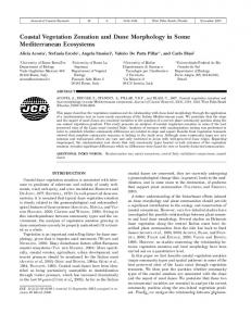


![[PDF] Heretics of Dune (Dune Chronicles) Full Collection - Google Sites](https://m.moam.info/img/260x300/pdf-heretics-of-dune-dune-chronicles-full-collecti_6478e54f097c4796708d4ff3.jpg)


