Australian Journal of Basic and Applied Sciences, 4(2): 208-216, 2010 ISSN 1991-8178 © 2010, INSInet Publication
Modeling of Traceability Information System for Material Flow Control Data 1
1
M.R. Khabbazi, 1M.D. Yusof Ismail, 1 N. Ismail, 2 S.A. Mousavi
Department mechanical and manufacturing, faculty engineering, UPM, Malaysia; 2 Department electrical and electronics, faculty engineering, UPM, Malaysia
Abstract: This paper focuses on data modeling for traceability of material/work flow in information layer of manufacturing control system. The model is able to trace all associated data throughout the product manufacturing from order to final product. Dynamic data processing of Quality and Purchase activities are considered in data modeling as well as Order and Operation base on lots particulars. The modeling consisted of four steps and integrated as one final model. Entity-Relationships Modeling as data modeling methodology is proposed. T he model is reengineered with Toad Data Modeler software in physical modeling step. The developed model promises to handle fundamental issues of a traceability system effectively. It supports for customization and real-time control of material in flow in all levels of manufacturing processes. Through enhanced visibility and dynamic store/retrieval of data, all traceability usages and applications is responded. Designed solution is initially applicable as reference data model in identical lot-base traceability system. Key words: Computer-aided systems; Manufacturing information system; Data modeling; Traceability; Entity-relationship modeling; Lot-based material flow control. INTRODUCTION Tracking and tracing represents the historic information on properties of objects in the object systems (Van Dorp, C.A., 2002). Traceability defines as ability to retain the identity of the product and its origin and usage nowadays concerns both government and business. It is the answer to the needs of several arenas of activities like Quality Management, Information Management, Risk M anagement, Logistical Flow, Commercial advantage, Evaluation of Management Demand (Töyrylä, 1999). The main idea of any tracing system is to obtain the required information within information quality factors like Accuracy, timeliness, sufficiency, easiness, reliability, and meaningfulness. Knowledge combination of Information System (IS) and Enterprise Resource Planning (ERP) provide the key solution to come by an efficient traceability system. Normally, ERP systems manage resources as batches and lots (Van Dorp, C.A., 2002) which is recognized as an efficient approach in steady and repetitive manufacturing processes. It becomes more complex and decreases its efficiency for example when is performed in Make-to-Order or Engineering-to-Order style. Nowadays the growing complexity of systems and products, as well as the tightening regulations addressing them, has created challenges to which existing systems have not answered completely (Rönkkö, M., 2006). Setting up a Tracing system based on factors like product characteristics, manufacturing system, and to meet all its requirements has always been a significant subject in manufacturing control. There are few reference models for tracing system, but necessarily not many of them are suitable for a particular type of product or manufacturing system and might not be justified for the others. Hence, the proper model in design, and justified tools, techniques, and technologies in utilization should be implemented for tracing material at all level of operations. The usage of traceability is not just restricted to applications such as recall, proof-of-quality, proof-of originality, or etc. In fact, in finding the roots of problems, remedy activities, and continuous improvement, the traceability system is a matter of essential assistance (Sohal, A.S., 1997). Tracing lots effectively is only possible with using an appropriate information system with an efficient approach of resource management. This paper addresses how to apply data modeling methodology for lot-based traceability information system in manufacturing with Make-to-Order basis. Among the common Data modeling methodologies Entity Relationship Modeling (ERM ) is adopted as our modeling method due to its popularity and usage. The requirements of tracking and tracing of material is elaborately addressed and correspondingly a computerized Corresponding Author: M.R. Khabbazi, Department mechanical and manufacturing, faculty engineering, UPM, Malaysia. Email:
[email protected] 208
Aust. J. Basic & Appl. Sci., 4(2): 208-216, 2010 traceability system conducted and implemented in a user-friendly and easy-to-understand way. The designed model promises to handle fundamental issues of traceability system effectively. It supports for customization and real-time control of material flow in all quality and production operation processes. W ith implementing the model, recording deviations and assessing their impact become easier. Furthermore, through enhanced visibility and dynamic store/retrieval of data, all traceability usages and applications is responded. Inform ation System and Traceability: Generally, there are four layers in manufacturing control system in which information layer is the key enabler and also key constraint for control system (Jansen-Vullers, M.H., C.A. Van Dorp, 2003). Moreover, due to the growth of automatic identification technologies, the key constraint of a tracing application switches to the storing data and creating reports (Rönkkö, M ., 2006). A possible way of dealing with uncertainties in the supply chain is the increased cooperation between the constituting organizations. Reference-information models are of importance to the infrastructural dimension of information and communication in the supply chain mostly in traceability. The exchange of information is tremendously important subject in this respect, especially in tracking-and-tracing. Information models are going to help so as they facilitate unambiguous information exchange between the organizations of supply chain. It is learned that information models have a strong structuring effect on the initiation and execution of projects for information systems. Information models describe the information systems of an organization (Van Dorp, A., 2004). Two important components of information models are: business process, and associated data resources. Information models can be used in three ways: (1) identification of information systems, (2) the standardization of data for development of information systems, and (3) the integration of information systems for different organizational functions. The main use of models has been in the area of identification and development of information systems for intra- organizational use (Van Dorp, A., 2004). However, it is logical to develop such models for interorganizational use in product chains. Traceability Levels: In the study of the repetitive and discrete items manufacturing, the scope of traceability ranges over the precision or resolution in physical integrity. Precision or resolution of traceability information depends on fidelity to physical integrity of items. The degree of precision and importance of items enables the level of traceability. Hence, two levels of traceability are identified: lot/batch level, and unit/item level. The nature of items determines the importance and level of traceability (Juran, M. and F.M. Gryna, 1988). The variables that determine the relative importance of traceability can be identified as: item value, item critically, and external environment. For example car manufacturers set requirements for the parts suppliers to have the capability to trace the source of any faulty automotive components (Sohal, A.S., 1997). Finally, the decision to implement traceability in a chosen level is made by justification through either cost and benefit analysis, or obediently compliance with direct external requirements from authorities, customers, etc. Here, the concept of traceability application is within the information layer through modeling of storing data regarding the elements and requirements of a traceability system with applicability in lot-based traceability level. Data Modeling: Data Model is a visual plan for building a database. A data model instance may be one of the three kinds (ANSI, 1975): conceptual (2) logical (3) physical. Early phases of many software development projects emphasize the design of a conceptual data model. Such a design can be detailed into a logical data model. In later stages, this model may be translated into physical data model. However, it is also possible to implement a conceptual model directly. Data model which is a diagram of data entities (objects) and their relationship is often used as the first step in designing a database and Object-oriented programming as well (Stair, R. and G. Reynolds, 2006) Data Modeling Methods: Data modeling methods are formalizing data entities and relationships between entities. There generally are four data modeling methods summarized in Table 1, include Richard Barker methodology (R. Barker, 1990), IDEF1X (1993), Entity-relationship model (ERM) (Chen, P.P.S., September, 1975 1976), and unified modeling language (UML) (Booch, G., I. Jacobson, 2000).
209
Aust. J. Basic & Appl. Sci., 4(2): 208-216, 2010 Table 1: D ata m odeling m ethods M ethod Richard Barker
Integration D EFinition for Inform ation M odeling (ID EF1X)
Entity Relationship M odeling (ERM )
U nifiedM odeling Language (U M L)
D escription A style of visual language to draw ERD s; Used by the O racle case m odeling tool
A Federal Inform ation Processing Standard (FIPS) based on the Integration Inform ation Support System (IISS); U sed to support the m anagem ent of data as a resource, the integration of inform ation system s, and the building of com puter databases The m eta m odel AN SI Standard in Inform ation Resource D irectory System s (IRD S); relational schem a database m odeling; U ses ER diagram s or ERD s for short. A graphical language for visualizing, specifying, constructing, and docum enting the artifacts of a softwareintensive system .
Features Barker shows how the data m odeling technique can be applied to develop high-quality, integrated inform ation system s. Readability and efficient use of drawing space and variation of the "crow’s foot" style of data m odeling that was favored by m any ID EF1X is used to produce a graphical inform ation m odel which represents the structure and sem antics of inform ation within an environm ent or system . Basic constructs of an ID EF1X are: B ox (to keep the objects), Lines (to connect the boxes), Attribute nam es (to describes characteristics of objects within boxes)
C an b e u sed as a basis for unification of different view s of data: the network m odel, the relational m odel, and the entity set m odel.
U M L diagram s represent three different views of a system m odel: functional view, static structural view, dynam ic behavior view
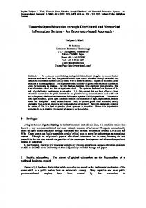
The ER Model was adopted as the meta model ANSI Standard in Information Resource Directory System (IRDS), and the ER approach has been ranked at the top methodology for database design and one of the top methodologies in systems development by several surveys of Fortune 500 companies. The ER model has influenced most of the major CASE tools, including Computer Associates’ ERW IN, Oracle Corporation’s Designer/2000, and Sybase’s PowerDesigner, and Microsoft Visio, as well as the IDEF1X standard. The ER model also serves as the foundation of some of the recent work on Object-oriented analysis and design methodologies and Semantic W eb. The UML modeling language has its roots in the ER model. Consequently, among the data modeling methodologies, ERM is chosen as our modeling method traceability. ERM: Entity-relationship model (ERM) is an abstract conceptual representation of structured data. It is used to produce a type of conceptual data model of a system. In case of designing a database, ERM is used to describe information needs or type of information that is to be stored in database at first. This conceptual data model at later stage, mapped to a logical data model which is turn, mapped to physical design. Entity Relationship Diagrams (ERDs) are a way of modeling real-world problems by organizing and structuring the data for a particular area of interest. This structured data is called a data model, and uses a visual language to draw objects, their inter-relationships and other relevant properties; ERDs call them entities, relationships and attributes respectively. The next section describes how the procedures are adopted for the modeling. Procedure Adopted for Modeling of Traceability: In this section a model for traceability system in manufacturing environment based on a case study is developed. ERM methodology is adopted to give a complete and easily understood description for the system. Figure 1 summarizes the procedures adopted in analysis and the modeling of traceability system. Procedures for Conceptual Modeling: First, conceptual modeling is used to describe the data structure of traceability information system. The architecture of the traceability database is organized into workable pieces using ERDs. This gives an abstract of the system structure in every corner of the system function. Identifying and analyzing the traceability requirements and needs is the first step in conceptual modeling. This stage identifies all the useful and relevant domains of application for traceability system to consider throughout the modeling.
210
Aust. J. Basic & Appl. Sci., 4(2): 208-216, 2010
Fig. 1: Procedure adopted for data modeling Identifying entities form traceability requirements as well as identifying relationship between them is the next step. Table 2 lists the names and describes the scopes of the entity types within traceability system. Entities are represented as rectangles. The relationships capture how two or more entities are related to one another which are gathered in the figure 5. Then, by using the specification from previous steps, conceptual model for the system is constructed. This will represent the structure of traceability system in a particular application domain. To picture all the application domains into one diagram the integration between diagrams is performed and relationships between other entities are developed after all steps of conceptual modeling processes for every domain. Table 2: D ata dictionary for identified entity types Entity Type Sum m ary/description O rder Inform ation holds the custom er/anonym ous order details Production Plan Inform ation identifies detail specification of production planning Purchase Captures needed information of raw m aterial/out sourcing purchasing Lot Inform ation identifies every Lot in the system with unique num ber O peration Stores needed inform ation of production operations Relation H olds inform ation of where-used and where-from for lots Q uality Inform ation holds all the quality control status Q uality Test O peration Inform ation holds the result for all kind of test operations Q uality Fault Resolve H olds needed inform ation of failure test result and corrective activity
Procedure of Physical Modeling: In previous parts conceptual and logical modeling described data structure and logic of representation of the system. Then, physical modeling is used to describe how physically data would be stored in a storage medium. Physical model includes all required tables, columns, relationships, and database properties for the physical implementation of database. Entity names have been changed to table names, changed attribute names to column names. Referential integrity, alternate keys, indexes, display formats, default values and other database rules are important parameters to deal with and implement in physical modeling of the system. by combining the conceptual model, logical model, and the physical model, the complete description of the traceability system is made. Developm ent of Traceability Model: Some basic contexts have been identified within the characteristics of traceability system. There are four elements identified that together define the full scope of lot traceability: Physical lot integrity, Data collection, lot-process linking, and reporting (Steele, D.C., 1995). In the other hand, there are five techniques distinguished in material tracking application: (1) Lot integrity control (2) Processing control (3) Build control (4) Inspection and test (5) Field activity and modification control (Caplan, F., 1989). A lot-based level of traceability system intrinsically is structured based on the mentioned elements and contexts. Accordingly, the traceability requirements and needs are highlighted and described thereafter. Conceptual Modeling: Identification and Classification of Traceability Requirem ents and Needs: Distinct case study in car component industry was analyzed on its requirements for traceability. The case on producing all kinds of metal washers was researched. The registration of data on customer orders in different amount of size and types in a relatively random time of order was considered as one important requirement.
211
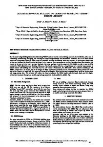
Aust. J. Basic & Appl. Sci., 4(2): 208-216, 2010 Purchasing raw material with different standards and specifications, or semi-final products (outsourcing) is performed to fulfill the demand of customer order. Registration of this process helps investigations to have information about the initial lot (parent) and considered as another important requirement for traceability. Several traceability applications are associated with quality problems. T he problems of quality are associated with quality control and the management of quality information (Tak, M.W . and W .L. Hang, 2002). Quality data are considered as operation objects in domain of quality control and management rather quality characteristics in view of operation domains (Tang, X.Q. and H. Yun, 2008). So, registration of quality data for lots is considered as very important requirements for traceability system. Generally, the traceability system has some core requirements (Jansen-Vullers, M.H., C.A. Van Dorp, 2003). Registration of data for any operation on lots to achieve the final product, need for upstream and downstream investigation upon where-used and where-from for lots, and also identifying lots itself easily, were essentially viewed as the core requirement for the traceability system. Identification of traceability requirements is categorized in four distinguished parts presented in figure 2. Identification of entity types and relationships is performed and the model for each part is fabricated. Later, to achieve the comprehensive conceptual model for traceability system, all designed models are integrated together as one.
Fig. 2: Traceability requirements This classification of requirements helps to easier identification of entities and relationships between them of each part to fabricate the final model. Identification and Modeling of Entities and Their Relationships: Data models consist of entity types and relationship types between them. The possible entity types and their relationships for all of the four recognized traceability requirements are modeled and the Quality Lot requirement is explained next. The title and description of all identified entity types, and relationship description between them are illustrated in table 2 and figure 5. Quality Lot: The entity types of Quality, Quality Test Operation, and Quality Fault Resolve are identified for quality data and Lot entity type for identification of lots. These mentioned entity types play an important role in tracing the Quality data for each typical lot which are required to fulfill many fundamental needs for desirable tractability system. Each single record in the mentioned entity types has a unique traceable identification number which is efficiently applicable for possible retrieval event. A bill of quality-id is obtained when lot entity type is investigated through one particular lot-serial-number. A list of zero, one or many Test Operation data is recorded for each specific Quality-id and could be retrieved easily where Quality and Quality Test Operation entity types have this unique Identification number in common. Zero, one or many records of Quality Fault Resolve entity type is initiated by zero or one respected Quality Test Operation entity type. The Quality Fault Resolve entity type is used to store information about any remedy activities that is initiated by zero, one or many quality control results (e.g. segregation). Figure 3 illustrate the modeling of Quality Lot traceability requirement. Integration and Fabrication the Final Conceptual Model for Traceability System: Next, the integration of designed models is discussed and developed by relationships between entity types and the final conceptual data model is presented. Through integration process two other important relationships were identified. Fist one correlates Production Plan entity types to Operation type which helps the system to have the chance to trace which operation belongs to which order. Second one correlates Purchase entity type to Quality entity type which provides quality information data for purchased items. These two important linkages are illustrated within the integrated designed model shown in figure 4.
212
Aust. J. Basic & Appl. Sci., 4(2): 208-216, 2010
Fig. 3: Quality Lot modeling
Fig. 4: Integrated traceability model
213
Aust. J. Basic & Appl. Sci., 4(2): 208-216, 2010 In manufacturing planning, products are brought into being by operations that are prescribed by orders and initiated by production planning. Hence, orders should be linked to operations through production planning. A production plan makes happen zero or more operations. Zero, in this case, an entry of a Production Plan not requires an immediate entry of the Operation, e.g., scheduled for one week later. Moreover, there are some quality operations and consequently some quality data which are of so importance in a traceability system that are enabled by purchasing either new raw materials or outsourcing items. The information of purchasing that is invoked by an order and is stored in Purchase entity type puts into effect quality activities which is another important relationship which is added the final integrated data model. A purchase put into effect zero or many quality activities. Zero, in this case, an entry of a Purchase not requires an immediate entry of the Quality, e.g., the results of material analysis test comes thereafter. The only interrelation that is not explained so far is the one that is between Order entity types and Lot entity type which is also depicted in the integrated model overview. Order of one item is contained in zero or more lot, and every lot comprise of one order. because of each order registered belongs to one type of item with the desired quantity, so any information about the products can be achieve by investigation in Order and Lot entity types. The model is devoted to traceability of dynamic data in information layer of manufacturing control system rather than unification with the associated static data of the system (e.g. identification documents for suppliers, products, personnel, equipment, machines, and so on and so forth.). Physical Modeling: After the logical model, the physical modeling is applied to capture all details of traceability modeling before implementation of the model. Identification of Key, and Storage Requirem ents (Blueprint): Next, identification of all keys, and storage requirements of traceability system is discussed. Each entity type is uniquely identified as discussed through logical modeling. This identifier is called a primary key. There are some entity types that are identified as referenced (i.e. an attribute type in an entity type is referred by a primary key of another entity type) by a foreign key which is explained in Table 3. Table 3: Identified keys of all entity types Entity Type U nique identifier (prim ary key) O rder O rderSerialN o Production Plan ProductionPlanID Purchase PurchaseID Lot LotSerialN o Relation RelationID Q uality Q ualityID Q uality Test O peration Q TestO prID Q uality Fault R esolve Q faultR slveID O peration O perationID
Referenced identifier (foreign keys) OrderSerialN o OrderSerialN o ProductionPlanID , PurchaseID , O rderSerialN o HighLotID (LotSerialN o), LowLotID (LotSerialN o), Q ualityID , OperationID LotSerialN o, PurchaseID QualityID QualityID , Q TestO prID ProductionPlanID , LotSerialN o
Every entity type has many attribute types which provides space to record information for each entry. In a database environment each entity type is called a table. Attribute entity types are so-called fields (columns). Any field has some properties to classify the type of the field to achieve a more efficient storage or retrieval process of data. Several tables are prepared for every entity types in order to describe the storage requirements of designed model. Data types of Auto-number, text, number, time/date, and yes/no, are considered to cover all corresponding types of data in the model. Table 4 describes the attributes, keys, storage requirements of “Quality Test Operation” entity type (i.e. table in database programming) for the system, thus enabling traceability for detail information of quality data. Quality test operation names could be predefined to the system to prevent undefined or wrong test practice. The next step is to fabricate the physical model diagram for traceability system which illustrates all entity types with associated identifiers, keys, attributes, and relationships. Fabrication of Physical M odel for Traceability System: Physical data model is a representation of a data design which takes into account the facilities and constraints of a given database management system and is derived from logical data model. The entity names have been changed to table names, changed attribute names to column names, assigned nulls and not nulls, and data type to each column. The identified tables, columns, relationships in addition to all other database properties are diagramed in figure 6 as the physical data model for traceability system. 214
Aust. J. Basic & Appl. Sci., 4(2): 208-216, 2010
Fig. 5: Cardinality and relationship between entity types
Fig. 6: Physical model of traceability system Table 4: Attributes, keys, and storage requirem ents of Q uality Test Operation table Attribute D ata type D escription Q TestO prID Autonum ber Prim ary KEY ; N um ber uniquely identifies one Quality test operation; N O null entry; "Q TO ID "# display form at. Q ualityID N um ber Foreign KEY ; Num ber identifies related Q uality that enrolls test operation. There has to exist one row in Lot table with this corresponding num ber; N O null entry; "Q ID "# display form at TestOperationN am e Text D escription of the test nam e; N O null entry. Q ualityPersonnelCode Text Identification of responsible quality personnel; N O null entry. D ocReferenceN o Text Identification of respected reference form or docum ent; N O null entry. O PCN o Text Identification num ber of O peration Process Chart. Item Code Text Identification code of Item to be tested; N O null entry. StartD ate D ate/Tim e Start Tim e and D ate of test operation StopD ate D ate/Tim e Stop Tim e and D ate of test operation.
215
Aust. J. Basic & Appl. Sci., 4(2): 208-216, 2010 Conclusion: This paper focuses on data modeling of lot-based level traceability in information layer of manufacturing control system for material flow. The model is able to trace all associated data throughout the product manufacturing from order to final product. All elements and requirements of traceability system are covered efficiently with ERM methodology. A case in car component industry is provided and it illustrates the problems of traceability to be solved. The resulting three models (i.e. conceptual, logical, and physical) are used for the implementation of a computerized traceability system that manipulates data dynamically to keep the information up to date and guarantees a reliable report generating system for different kinds of traceability applications. The models reduce complexity of the system analysis and modeling with the help of graphic representations, such that it is easy to understand and operate from a designer’s viewpoint. It also makes the movement from system analysis to implementation go more smoothly and quickly. Inherently, the real-time feedback function of integrated information system improves the flow of information. In traceability system, it supports for customization and real-time control of material in flow in all quality and operation processes such as defect rate, yield amount of product items, customized lots for reworks or special orders by means of common traceability information console. By implementing the model, recording deviations and assessing their impact become easier. The integrated traceability database also improves the availability of different data analyses and the ease of information access with the help of computerization and the presence of effective presentation interfaces. Through enhanced visibility and dynamic store/retrieval of data, all traceability usages and applications are well responded. REFERENCES ANSI, 1975. ANSI/X3/SPARC Study Group on Data Base Management Systems; Interim Report, FDT (bulletin of ACM SIGMOD), 7(20). Barker, R., 1990. Case Method: Entity Relationship Modeling: Addison-W esley. Booch, G., I. Jacobson and J. Rumbaugh, 2000. OMG Unified Modeling Language Specification, Rational software corporation, Version 1.3 First Edition: M arch 2000,, Retrieved 10 September, 2008, from http ://www.omg.org/docs/formal/00-03 -01 .pdf. Caplan, F., 1989. The Quality System, Pennsylvania: Chilton Book Company. Chen, P.P.S., September, 1975 1976. The entity-relationship model - toward a unified view of data, ACM Transactions on Database Systems (TODS), 1(1): 9-36. IDEFX1, 1993. Announcing the standard for Integration Definition For Information Modeling (IDEFX1), Fed e ra l Info rm atio n P ro ce s sin g S tan d a rds P ublic a tio n 1 8 4 ,, R e trie ve d J uly 2 0 0 8 , fro m http://www.idef.com/IDEF1x.html. Jansen-Vullers, M.H., C.A. Van Dorp and B.A.J.M ., 2003. Managing traceability information in manufacture, International journal of Information Management, 23(5): 395-413. Juran, M. and F.M. Gryna, 1988. Quality Control Handbook, fourth ed.: McGraw-Hill Inc. Rönkkö, M., 2006. A model for item centric material control in manufacturing, Master of Science thesis, Helsinki University of Technology, Finland. Sohal, A.S., 1997. Computerized parts traceability: an implementation case study, Technovation, 17(10): 583-591. Stair, R. and G. Reynolds, 2006. Fundamental of Information Systems, third ed.: Thomson. Steele, D.C., 1995. A structure for Lot-tracing design, Production and inventory management journal, 36(1): 53-59. Tak, M.W . and W.L. Hang, 2002. Modeling of a quality control information system for small- to mediumsized enterprises, Integrated Manufacturing systems, 13(4): 222-236. Tang, X.Q. and H. Yun, 2008. Data model for quality in product lifecycle, Computers in industry, 59(2-3): 167-179. Töyrylä, 1999. Realizing the potential of traceability: a case study research on usage and impacts of product traceability, Thesis Thesis, Helsinki University of Technology, Finland. Van Dorp, C.A., 2002. Extending ERP with Recipe and M aterial Traceability, in Eight Americas Conference on Information Systems. Van Dorp, A., 2004. Reference-data modeling for tracking and tracing, Thesis Thesis, W ageningen Agricultural University, The Netherlands.
216