unforeseen events, secondly monitors the execution of what we call the agent's abstract ... schedule a set of possibly concurrent patterns of behaviour, being activated by ...... In Proc. of the 1st International Conference on A I Planning Systems.
Modeling Reactive Behaviour in Vertically Layered Agent Architectures Jhrg P. Mfiller, Markus Pischel, Michael Thiel DFKI, Stuhlsatzenhausweg 3, D-66123 Saarbriicken A b s t r a c t . The use of layered architectures for modeling autonomous agents has become popular over the past few years. In this paper, different approaches how these architectures can be build are discussed. A special case, namely vertically layered architectures is discussed by the example of the INTERRAP agent model. The paper focusses on the lower
levels of the architecture which provide reactivity, incorporate procedural knowledge, and which connect the cooperation and planning layers with the outside world. We claim that the lower system layers are likely to become a control bottleneck in vertically layered architectures, and that very careful modeling is required to produce the desired agent behaviour. 1
Introduction
Over the past few years, several different architectures for autonomous systems have been proposed in the (D)AI literature (e.g. [2, 8, 3, 14, 4, 7, 10, 5, 16, 15]). An important class of approaches to modeling systems that have to behave in a goal-directed manner in a complex, changing environment are layered architectures. This approach regards an agent as consisting of several hierarchical functional modules, representing the different requirements on an agent, such as reactivity, efficiency, goal-directed behaviour, and coordination with others, as well as representing different qualities and levels of abstraction concerning the agent's knowledge (e.g. from raw sensor data to the description of complex, rather abstract situations). Basically all these approaches are somehow linking the input into an agent (its perception) into a kind of output from the agent (normally regarded as the actions the agent performs). Most of them define an agent cycle using perception in order to update the agent's internal state, i.e. its beliefs about the world, then use this world model as a basis to do some kind of decision-making (planning), possibly taking into account other agents, finally leading to a decision as to what to do next, i.e. to the actions to be performed in the next agent cycle. Possible layers of these agent models incorporate perception and action, reactivity (behaviour-based layer), local planning, cooperation, modeling, intentions, and learning. In this paper, we identify and describe several basic classes of layered architectures. We focus on a specific class, namely vertically layered architectures, and describe a concrete instance, the agent architecture INTERFtAP. INTERRAP consists of two basic units, the agent control unit and the agent knowledge base, which both share a hierarchical structure. The four control layers are (from lower to upper): the agents' world interface definition (WIF); the behaviour-based
262 component (BBC); the plan-based component (PBC); and the cooperation component (CC). The agent knowledge base is designed as a hierarchical blackboard system which is basically splitted into four layers corresponding to the structure of the control component. It is not the purpose of this paper to give a thorough description of the agent architecture; this has been done elsewhere [13]. Rather we argue that the way the lower layers are modelled is of special importance in vertically layered architectures since every piece of information and any control discussion has to pass them. Therefore, we focus on the design of the behaviour-based component of the INTERRAP model. Several aspects will be discussed that have to be taken into account and problems which have to be solved when dealing with this problem. As an example, we will look at the world interface and behaviour-based component used to implement KHEPERA miniature forklift robots. The different functionalities defined at the BBC layer and the basic control structures used to schedule the patterns of behaviour will be described. Different mechanisms for pattern selection will be discussed in the light of this example, such as static and dynamic priorities between patterns, the use of genetic algorithms, suppression mechanisms, and knowledge-based methods. 2
Layered
Architectures
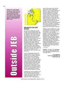
Among the many instances of layered architectures mentioned in the introduction, we can distinguish between two fundamental classes: horizontally layered architectures (such as the ones developed by Brooks 112], Kaelbling[8], and Ferguson [4]) and vertically layered architectures (such as MECCA[15] and INTERRAP[13]). Whereas all the layers of an agent have access both to the perception and action components in horizontal architectures, only one (and normally: the lowest) layer has a direct interface to these facilities in the vertical approach. This is illustrated by figure 1. Ferguson's Touring Machines architecture [4] is a very good example of a horizontally layered architecture (figure la). It consists of three control layers, the reactive layer, the planning layer, and the modeling layer. All the layers work concurrently, have access to the a g e n t ' s perception and may propose actions. In order to achieve coherence, Ferguson's agents employ a set of global control rules which may suppress the input to a certain layer (suppressors) and which may censor the output of a layer. Brooks [2] employs similar mechanisms (suppression and inhibition) in order to enable higher layers to suppress inputs to and to inhibit output from lower layers. The need for a centralized control authority and the complexity of its design seems to be one of the key problem with horizonatally layered architecture. In an architecture consisting of n layers, even if we restrict ourselves t o bilateral interactions between layers, each layer may theoretically interact with each other 1 Note that Brooks' approach is often referred to as vertical decomposition approach, since it divides up the functionality of an agent in a hierarchical manner; this should not be confounded with the fact that the access to perception and action is possible for each layer, and that it therefore describes a vertical architecture in our notation.
263 b)
Layer Layer
Layer Layer
a) Horizontalarchitecmx,e
n n-I
2 1
t Layer ] ~ Layer
n t n-I
t. L a y e r I v Layer
2 I
.t T
pLayer pLayer
n n-l|
t
*Layer 2 * ~Layer
1
b) and c) different kinds of verticalarchitectures
Fig. 1. Vertical and Horizontal Agent Architectures
layer, leading to ~ 2 bilateral cases to be described, each of which can be very complex itself. Thus, in horizontal approaches, the bottleneck is control. This observation has led to the development of vertically layered architectures, which impose certain restrictions on the possible interactions among different layers. An example for vertically layered architectures (figure lc) is the INTERRAP agent architecture [13]. which is the model underlying our work. INTERRAP describes an agent as consisting of trhee hierarchical layers, the behaviour-based component, the plan-based component, and the cooperation component. The basic concepts of INTERRAP are described in section 3. The MECCA architecture proposed by Steiner et al. [15] can be regarded as a variation of a vertically layered architecture (figure lb). Reasoning within an agent is regarded as running in four phases which are represented by four modules: goal activation, planning, scheduling, and execution. The main difference between INTERRAP and MECCA is that the modularization in the latter architecture is functional, whereas it is conceptual in the former; the MECCA modules correspond to different functionalities of an agent whereas the INTERRAP layers rather constitute different levels of abstraction of similar functionalities. Due to the nature of the flow of Control in vertical agent architectures, the way the lower layers are modeled are crucial for these class of agent models. On the one hand, using vertical architectures such as INTERRAP saves one from having to define the sort of global control knowledge that is specified in horizontally layered architectures: the only thing that needs to be done for an architecture with layers 1 . . . n is to define n - 1 interfaces between directly neighbouring modules. On the other hand, there is a price to pay for this convenience: anything the agent does must pass its lowest layer. In the case of the INTERRAP agent, the behaviour-based layer is the critical layer: this layer firstly has to react to unforeseen events, secondly monitors the execution of what we call the agent's abstract actions based upon commands from the local planning layer, thirdly must maintain constraints imposed by the local planning context, and, last but
264 not least, may be affected with commitments obtained by cooperative activities. Thus it is the task of the behaviour-based component to maintain and to schedule a set of possibly concurrent patterns of behaviour, being activated by the recognition of certain situations and by decisions made at higher layers of the agent architecture. What should become clear from this discussion is that whether a vertical agent architecture can be used successfully for modeling agents in a specific domain is to a large extent influenced by a more or less careful modeling of the lower layers of the agent as well as their interface to higl~er layers.
3
T h e INTERRAP Agent M o d e l
The main idea of INTERRAP is to define an agent by a set of functional layers, linked by a activation-based control structure and a shared hierarchical knowledge base. Figure 2 overviews the INTERRhP agent model. It consists of five
HIv~r~hl~d Agvet ~B
~ q ~ m ~ n Knowte~ (r a~tsxt) Joint Goahl I Plans
(metal context) Local GoalsI Plans WodclModel
(situational context) PsttermJof BeluvJour
Communica~on
A~ng w o r I d
lat
ENVIRONMENT
vrfQa~
I
Perception (WIF)
control flow
. . . . . . . . informationaccess
Fig. 2. The INTERRAP Agent Model basic parts: the world interface (WIF), the behaviour-based component (BBC), the plan-based component (PBC), the cooperation component (CC), and the agent knowledge-base. The WIF contains the agent's facilities for perception, action, and communication. The B B C implements and controls the basic reactive behaviour of the agent as well as its procedural knowledge (abstract actions).
265
It is based on the concept of patterns of behaviour. These allow an agent to react flexibly to its environment, and to perform routine tasks efficiently without requiring explicit symbolic planning. T h e PBC contains a planning mechanism which is able to devise local single-agent plans. The plans are hierarchical skeletal plans whose nodes may be either new subplans, or executable patterns of behaviour, or primitive actions. Thus, the plan-based component may activate patterns of behaviour in order to achieve certain goals. Planning helps an agent to act in a goal-directed manner. Moreover, in a multi-agent context, planning is necessary to coordinate actions of agents. For instance, agents should be able to devise joint plans ([9]) to cope with special situations. This functionality is provided by the cooperation component CC. The agent knowledge base is designed as a hierarchical blackboard system which is basically splitted into three layers corresponding to the structure of the control component: the agents' world model containing its object-level beliefs about the world; the mental model holding autoepistemic knowledge, and knowledge about the agent's mental state (goals, plans, intentions); finally, the social model representing what an agent believes about other agents, as well as information about joint goals, plans, and intentions Information access is possible only from lower layers to higher layers of the knowledge base. For example, the PBC can access information about the world model, whereas the PBC does not have access to planning or cooperation information. The overall control behaviour of an INTERRAP agent emerges from the communication among the different modules. Based on interesting events happening in the world (situations) recognized by the agent, control is shifted upward until the appropriate layer to deal with the situation. There are three generic execution paths describing general classes of problem-solving: the reactive path, the local planning path, and the cooperative planning path. The reactive path treats a situation by direct execution of a pattern of behaviour, without involving explicit planning. The local planning path makes use of the local planning resources of the agents: control is shifted upward from the BBC to the PBC where a plan is devised. Finally, the cooperative planning path is selected if a situation cannot be satisfactorily solved by local planning. Except these generic paths, there exist other, more complex interactions, especially between the PBC and CC. For example, in order to make a decision in a negotiation protocol, it can be necessary to determine the possibility and the cost of locally solving a specific subproblem. In the rest of this paper and for the reasons motivated in the introduction, we will focus on the BBC and WIF components. We refer to [13, 12] for a more detailed description of the planning and cooperation layer and of the control aspects of the architecture.
4
Behaviour-Based
Modeling
In this section, the lower layers of the INTERRAP model are described in detail. Subsection 4.1 discusses the agent's world interface. In subsection 4.2, we present
266
our concept of patterns of behaviour. Subsection 4.3 describes the basic control cycle of the behaviour-based component.
4.1
The World Interface
As stated above, the world interface implements the basic facilities of an agent for performing actions, handling messages, and perceiving its environment. Defining the interface between the behaviour-based layer and the world interface layer is an important design decision. For many applications, an obvious possibility to define the world interface is by using the primitives given by the application itself. This can be the case for example in a robot application, where the designer's possibility to model the behaviour of its robots is based on the existing hardware. Therefore, we call this interface the hardware interface (HI). The advantage of this approach is that the separation is clear and given in advance. Moreover, the behaviour-based component may directly access all the functionality of the system; thus, control is maximized. On the other hand, the behaviour-based component becomes machine-dependent, and is based on a low degree of abstraction. Different approaches to separating WIF and BBC are what we call the symbolic//subsymbolic interface (SSI) and the abstraction interface (AbI); according to the former, the quality of reasoning (symbolic or subsymbolic) is the criterion for dividing between WlF and BBC. That means, subsymbolic reasoning is done in the WlF, the BBC starts where information is stated explicitly at a symbolic layer. The advantage of the SSI approach is that it can be defined more flexibly than HI and increases abstraction and hardware independence. However, it offers only little help in deciding what should be represented at a symbolic and at a subsymbolic layer, respectively. The latter approach, the abstraction interface, can overcome this weakness: the main idea behind it is to define logically primitive actions for a given application. Experience has shown that it is easy to specify this interface for many applications. In the simulation of the loading dock, for example, it turned out to be reasonable to specify the actoric world interface of the forklifts by primitive actions such as walk_ahead, turn_left, turn_right, grasp_box, put_box. Thus, a pattern of behaviour goto_landmark may call walk_ahead as a primitive action having the agent move to the field in front of it. In the KHEPERA implementation with real robots, moving one field ahead is by no means primitive for a robot. Rather, it is a complex action, implying following the guiding line, controlling speed and avoiding collisions. The functionality offered by the hardware interface of the robots such as read_speed(), set_speed(}, read_proximity_sensors, read_floor_sensors, is partially too low-level. Therefore, the WlF-definition in the KHEPERA implementation lies somewhere in between and consists of a set of functions such as go(speed), right_curve(intensity), left_curve(intensity), which are more abstract than e.g. set_speed, but more specific than walk_ahead..
267
4.2
Patterns of Behaviour
Patterns of behaviour are the essential structural primitives of the behaviourbased component. They incorporate the reactive abilities and the procedural knowledge of an agent. The former allow an agent to react quickly, flexibly, and often avoiding explicit replanning, to certain unexpected events, the latter provide the primitives for the plan-based component of an INTERRAP agent S t r u c t u r e According to their activation/effect functionality, we distinguish between four basic types of patterns: reactors, control modifiers, knowledge modifiers, and procedures. Reactor patterns are triggered by external events and cause the agent to perform some sort of action. For example, stopping when facing an obstacle in front of it should be implemented as a reactor pattern. Knowledge modifiers are patterns that change the internal state of the agent (e.g. its knowledge). They are activated by changes in the world perceived by the agent (i.e. by changes in the agent's world model). In our approach, they are used to implement the recognition and classification of situations and world model abstraction. Similar to knowledge sources in a blackboard system, there are patterns that recognize and abstract specific situations (e.g. another agent ahead, standing in a narrow corridor). Other patterns recognize more complex pattern based on the results of the lower-level knowledge modifiers. Control modifiers are patterns that expand control to the planner by calling the PBC. For example, a pattern t r e a t _ o r d e r _ b e h will activate the PBC with the goal of planning an order as so on as the agent has received a transportation order. Finally, procedure patterns implement what is viewed as abstract actions by the planner. For example, moving straight ahead to a landmark is likely to be implemented as a procedure in a robot application, i.e. is atomic from the perspective of the PBC. These patterns can be compiled down from plans. Since we assume that the planner basically plans actions, our classification does not take into account patterns that are triggered internally and yield only a modification of the agent's world model or an activation of the planner. Based on this classification, patterns of behaviour are abstractly defined as frame structures as shown in figure 3. The definition of a PoB consists of a description part and an execution part. The description part contains meta-information describing the pattern of behaviour which is needed for the control mechanism, such as the activation condition and several monitoring conditions. The execution part contains the executable body of the pattern, which is started if the pattern is selected by the control mechanism. In the following, the elements of both parts will be described in more detail. T h e D e s c r i p t i o n P a r t The basic elements of the description part of a PoB are its activation condition and a set of monitoring conditions. All these conditions describe situations which are relevant for the selection a n d / o r execution of the pattern and thus provide meta-information about the pattern. The activation condition is a formula which whose satisfaction in a certain state of the world
268
( PoB :name :type :args :activation :monitor :failure :success :holding :exceptions :post :exec.body
/* /lame of p a t t e r n */ /* r e a c t o r , m o d i f i e r , p r o c e d u r e */ /* arguments */
/* /* /* /* /* /* /* /*
a c t i v a t i o n condition */ conditions monitoring execution */ f a i l u r e condition: s t o p e x e c u t i o n */ condition f o r s u c c e s s f u l termination */ conditions t h a t must h o l d d u r i n g e x e c u t i o n */ u s e r - d e f i n a b l e exceptions */ condition t h a t must h o l d a f t e r e x e c u t i o n */ executable body;e.g, c o n t r o l program */ )
Fig. 3. Patterns of Behaviour
is a precondition for the PoB to be applicable in this world state. Thus, in each state of the world, there is a set of active patterns. Once one of the active patterns has been selected by the control mechanism (see below), its execution is monitored by a set of monitoring conditions. These conditions describe exceptions which may occur during the execution of a pattern. An exception is a tuple (Cond, Act), where Cond is a state formula, and Act is an action description. The operational semantics is that if Cond becomes satisfied by the current state of the world, Act is executed. Apart from a set of user-defined exceptions, there are some exceptions whose action parts possess a fixed semantics: For example, if the failure condition becomes satisfied during the execution of the pattern, execution is aborted with a failure; if the termination condition becomes satisfied, the pattern is terminated successfully. This allows to deal with the case that the purpose of a pattern is reached by coincidence. Failure and termination conditions are of the form (Cond, Clean-Up) where Cond specifies the actual condition and Clean-Up specifies certain activities which have to be performed in order to ensure consistent termination/failure of the PoD. The necessity of the Clean-Up part will become obvious by the example in section 5. The conditions of an active pattern are monitored by so-called guards, which are basically knowledge modifiers, i.e. patterns of behaviour which become active when the respective condition (e.g. the termination condition of the parent pattern) becomes true. For example, the termination condition for a PoB for moving to a landmark is satisfied when the agent has reached the landmark. This again is monitored by a guard pattern. Finally, a post condition may be specified which describes the essential properties of the world after the execution of the pattern. Unlike the termination condition, the post condition is not monitored during execution. However, it may be accessed by the control mechanism in order to determine the degree of satisfaction for a PoB, that can be used as a means for determining the priority of a pattern (see also subsection 4.3 and [6]).
269
T h e E x e c u t i o n Part The execution of a pattern of behaviour will cause the agent to perform actions in the world, to read its sensors, or in specific situations will lead to calling the plan-based component. The execution procedure of a PoB is specified in its execution part. Since the bodies of patterns of behaviour may be complex (for example: goto_landmark), and since several patterns of behaviour may be active at a time, the granularity of execution is a critical topic: a scheduling mechanism is required that allows stepwise execution which m a y alternate between different PoB. Execution granularity must not be too coarse in order to keep reactivity of the BBC, nor must it be too fine in order to reduce the overhead for changing between the execution frames of different PoB's too often. In the sequel, a language for describing the bodies of PoB is defined. An Execution Language for PoB An execution language for PoB needs to satisfy the following requirements:
- It has to allow stepwise execution providing reasonable stepwidths and allowing to specify atomic activities that must not be interrupted. - Its primitives should be the activation of WIF primitives, such as actions and sensors, and calls to the plan-based component. - It shall offer language constructs such as composition, tests, and iteration. For determining the values of test and iteration predicates, access to the knowledge base is needed. - Since patterns of behaviour may be compiled down from plans, they will activate other patterns of behaviour; sequential and parallel activation should be supported. Figure 4 shows the EBNF syntax of a language fulfilling these requirements. Keywords (e.g. w h i l e , if) appear in bold face, primitives in italics. Dots denote incomplete definitions. In the sequel, we will define the semantics of the execution language.
Semantics The operational semantics of the language presented above is defined by an interpretation function step which takes as argument a language expression. Step can be recursively defined as follows: step({ P }) de=f set block = true; step(P) ; set block = false step(P1; P2) aej step(P1); step(P2) step(while c do P o d ) de_j if c then step(P; while c do P) else true fi step(if c then Pl else P2 fi) de_j if c then step(P1) else step(P2) step(ex(P)) dej ex(P) step(call(pbc, X)) de..f call(pbc, X) step(activate([P[Rest])) de_f activate(P); step(activate(Rest)); step(activate(D) ) at, = true
270
::-- block [';' program] ::= '{' block-content '}' I primitive-instr ::= while condition do block-content od I if condition t h e n block-content else block-content fl I primitive-instr primitive-instr ::= wif-execution I pbc-call I pob-activation I modifier condition ::= atomic formula wif-execution ::= e x '(' wif-primitive ')' pbc-call ::= call '(' p b c ',' d o '(' goal-specification ')' ')' I ... pob-activation ::= a c t i v a t e '(' pob-spec-list ')' wif-primitive ::= turn_left[ turn_right I ' go(' integer')' t 'right-curve(' integer')' l 'left_curve(' integer ')'1 read_sensors I ... goal-specification::= formula pob-spec-list ::= '[' { pob-specification }+ ']' ')' pob-specification ::= pobname '(' parameter-list ')' modifier ::-- assert ground formula I r e t r a c t ground formula
program block block-content
Fig. 4. EBNF-Syntax of the Execution Language The function step is described using a meta language. Ex, call, activate denote the physical actions of executing a WIF primitive, calling the PBC, or activating a pattern of behaviour. [HIT ] denotes a list with first element H and rest T. While do od and if then else fi are interpreted as usual. In order to distinguish the meta language constructs from their object-level counterparts, we do not use bold type for the former ones. The reason for the treatment of blocks will become clear in subsection 4.3, where the stepwise execution mechanism is described. 4.3
The BBC Control Cycle
Up to now, we have described patterns of behaviour. The BBC of an agent consists of a set of patterns of behaviour and of a pattern maintenance unit which implements the control mechanism of the BBC. Next, in this subsection, this control mechanism is described. O v e r v i e w In order to achieve the requirement of reactivity, the BBC control is implemented in a processing cycle: in each loop, it monitors changes in the world model caused by perception and commands received from the plan-based components. According to the new world state, several PoB may be active because their activation conditions are satisfied or because they have become active in an earlier world state and have not yet been finished. The basic task of the BBC cycle is to determine the active patterns based on the updated world model, then to select one PoB for execution in the current cycle, and to execute it one step further. The control cycle algorithm is shown in figure 5. At the beginning of each cycle, the agent updates its world model based on its current perception and based on activation messages from the PBC and from other patterns
271
r* Variables: t* POBSET: t* ACTi: r* INACTi: t* PERCi: t* ACT-REQi: t*
PoBi:
t*
WMi:
*/ set of all patterns of behaviour
set of PoB which are active by the end of cycle i set of PoB which are not active by the end of cycle i perception at the beginning of cycle i PoB activation requests at beginning of cycle i pattern of behaviour selected for execution in cycle i world model in cycle i
*/ */ */ */ */ */
bbc-cycle(POBSET) { i:=0; ACTi := 0; WMi := init_kb; INACTi := POBSET; repeat WMi+ i := update-state(WMi, PERCI+I, ACT-REQi+ 1); ACTi+I := det_active_pob(ACTi, INACTI, WMi+I); PoBi+l := select_pattern(ACTi+l, WMI+I); WMi+I := execute_pob(PoBi+l, WMir INACTI+I := POBSET - ACTi+I; i:=i+1 forever } Fig. 5. The BBC Control Algorithm
of behaviour. The actual processing of the cycle runs in three phases, which are discussed in more detail in the following subsections. D e t e r m i n i n g A c t i v e P a t t e r n s The function det_active_pob(Wll, ACT, INACT) is used in each BBC cycle in order to determine the current set of active patterns of behaviour. In the following, let 7) denote a set of patterns of behaviour, and let L: denote a set of propositions (denoting e.g. an agent's world model). For a pattern p E 7)a let p.AC, p.TC, and p.FC denote p's activation, termination, and failure condition, respectively. A pattern is called active at a certain time if the activation condition of the pattern is satisfied at that time, or if the pattern has been activated at an earlier time and has not yet terminated or failed. Thus, det_active_pob is a function 5 : 2 ~ x 2~' x 2~' ~-~ 2"p, where
~ ( W Mi +I , Acti , InActl ) def: {p 9 InActilWMi+l ~ p.AC} U {p' 9 Actil3j.j < i A W M j ~ p.ACA ~3k.j < k < i A (WMk ~ p.TC V WMk ~ p.FC)}. P a t t e r n S e l e c t i o n We see that different PoB may be active at a time. However, our model assumes a sequential model of execution. T h a t means, only one
272
pattern may have the control to initiate an action at a certain time. It is a consequence of this fact that one pattern must be selected for execution in each BBC cycle. This selection is performed by the function s e l e e t _ p a t t e r n ( A e t P L i s t ) . It is defined as a function ~r : 2 7' • 2 c ~ 7~. It is the task of this function to select the most urgent, most important, or most useful PoB to be executed in a specific situation described by the second argument of ~,, the agent's current world model. Pattern selection problem; it has turned out to be the core problem of behaviour-based modeling, and the way it is implemented is crucial for the behaviour of the agent, for its reactivity as well as for its capability to handle complex situations. In the following, we outline two approaches for modeling pattern selection, both of them based on a priority mechanism.
Static Priorities: The Maslow Pyramid Very often, we can identify classes of patterns of behaviour that are generally more urgent or more important than others. Based on a hierarchical classification of human needs by the psychologist Maslow [11], we defined four hierarchical classes of patterns of behaviour: PoB corresponding to physical goals (e.g. remain unharmed, avoid collisions, ensure energy supply), to task-related goals (e.g. perform transportation tasks), to social goals (e.g. help other agents), and PoB corresponding to optimization goals (explore regions, improve plans). Maslow claims that the lower-level needs have higher priority than the higher-level needs, and that the former must be satisfied before a human starts satisfying the latter. This classification of patterns of behaviour in an application results in a static preordering of the patterns, and allows to express e.g. that if an agent has a task to fulfill and it detects a threatening collision, the collision avoidance pattern has higher priority than the task-oriented pattern. In their DASEDIS architecture, [3] pursue a similar approach by associating behaviours with intentions and by defining a total ordering on the intentions. Dynamic Priorities: Degree of Satisfaction (DOS) The static priority approach has some serious drawbacks. Firstly, it provides no guidance to select between two patterns classified at the same classification layer. Secondly, the relative priority of a pattern often depends on the current situation. Thirdly, giving task-related goals a higher priority than social goals does not support cooperative behaviour. Strictly speaking, it would even imply that an agent only cooperates if it has no local tasks to achieve - which is definitely not what is intended. A better approach seems to be to compute the priority of a pattern dynamically based on its degree of satisfaction (a similar idea has been proposed by [6] in the context of decision-theoretic planning). The degree of satisfaction of a PoB is a function of the amount of resources consumed by the pattern, and of how much of the goal corresponding to the pattern has already been achieved. For example, the DoS of the pattern of behaviour goto_landmark can be expressed by
DoS(goto_landmark(Xa, Ya)) = 1 -
dist((Xs,
Yo), ((Xa,
Ya))
273
where ( X , , Ys), (Xc~rr, Yc~r~), (Xd, Yd) denote the start position, the current position, and the destination position of the agent, respectively, dist (Pl, P2) denotes the Euclidean distance between two points pl and p~. A general possibility to c o m p u t e the DoS is by comparing the actual state of the world with the post condition of the pattern. If we allow only conjunctive, pairwise independent formulae to define postconditions, and assume t h a t we can evaluate the t r u t h value of the partial formulae by simple matching against the world model, we can use the percentage of satisfied subgoals as a coarse measure for the degree of satisfaction. Another approach is to maintain statistical or heuristic models a b o u t the average (expected) time and resource consumption of patterns of behaviour, and to estimate the degree of satisfaction based on these models.
P a t t e r n E x e c u t i o n The execution of a pattern of behaviour which has been chosen in the selection phase is monitored by the function e x e c u t e _ p a t t e r n ( P o B , W~I). e x e c u t e _ p a t t e r n is a function c : ~ • 2 ~ ~-~ 2 z which determines the change of an agent's internal state by executing a pattern of behaviour in a given state. As stated above, the execution mechanism has to provide stepwise execution of patterns of behaviour. In the sequel, we will outline how an execution scheduling mechanism can be achieved by slightly modifying the interpretation function step defined in subsection 4.2. The main idea behind the scheduling algorithm is to define one execution step either as the (computation plus) execution of the next primitive instruction or as the execution of a block defined by the p r o g r a m m e r of the pattern. T h a t means, we provide a high-level scheduling mechanism which allows the p r o g r a m m e r to define the granularity of execution - and which also forces h e r / h i m to take the responsibility for selecting an appropriate choice. The function e x e c u t e _ p a t t e r n can be implemented by modifying the step function for primitive instructions as follows:
step(ex(P)) step(call(pbc, X))
step (activate ([P]Rest]))
step(activate(D) )
def
ex(P); if block = false then store_execution_frame; exit fi def call(pbc, X); if block = false then store_execution_frame; exit else true fi def activate(P); step(activate(Rest); if block = false then store_execution_frame; exit else true fi def true
b l o c k is a boolean variable which is set to true at each entrance into a block structure defined by the user, and set to false again when leaving the block. If a primitive instruction is processed, it is tested whether it occurred inside a block. If this is not the case, the current execution step is finished. Then, the execution frame of the pattern (which stores the local state of processing) is stored and control returns to the BBC cycle.
274
5
An
Example
The application that will be used to illustrate the model described in the previous chapter is the FORKS system. FORKS describes a simulation of an automated loading-dock, where autonomous forklift agents have to load and to unload trucks. In the loading dock, there are shelves which may contain different types of goods. We use a grid-based representation of the loading-dock. The forklifts can move from one square to the next, turn around, grasp and store goods, and communicate with other agents. Each agent has a certain range of perception, which it can observe. Currently, a physical implementation based on K H E P E R A miniature robots has been initiated, which differs from the simulation mainly by the definition of the world interface (see also section 4.1). The patterns of behaviour defined in the following refer to the K H E P E R A implementation. To give a better idea how the BBC works, we present some examples of PoB in our FORKS system and trace some steps of the control cycle.
( PoB :
name
:type :args :activation :monitor :success
:exception
gotoJandmark procedure (destX,destY) msg(activate(goto~andmark(destX,destY))) my_pos(destX,destY) ([(return~tatus(waXk.ahead)
ffif a i l u r e ,
enable(dodge))]) :exec_body while true do a~tivate(turn_to~ree_dir(destX,destY)); activate(walk.head); od
) ( PoB :name
dodge
:type :activation :exec_body
reactor object~n-front activate(step_aside);
Fig. 6. Patterns of Behaviour goto_landmark, dodge The name of the PoB illustrated in figure 6 is goto_landmark. It is a procedure which is activated by a call (message) of the PBC or another PoB and it receives the destination field as argument. The purpose of goto_landmavk is to move the robot from its actual position to the destination field. There are no monitors for failure, holding or other exceptions. Only successful termination is checked:
275
the PoB succeeds, if the robot stands on the destination field. In the body, two further PoBs are called, turn_to_free_dir(x,y) turns the robot in a direction, where the field in front of it is free and a step forward decreases the distance to the destination field, if such a direction exists, walk_aheadmakes the robot move one field ahead. When this PoB gets active (by a call from the PBC) and is selected to be executed, the function step processes the body until it reaches the expression activate(turn_to_free_dirO). Now the PoB turn_to_free_dir becomes active and goto_landmark is suspended until turn_to_free_dir is finished, i.e. the body will not be executed furthermore, but the success-monitor keeps running. If turn_to_free_dir succeeds, goto_landmark continues and on the next execution step walk_ahead will be activated. If turn_to_free_dir fails, goto_landmark fails too. The activation of walk_aheadbehaves the same way, except that its failure is handled by an exception: the reactor pattern dodge is enabled which tries to move around the obstacle; walk_aheadfails only in case dodge also fails. If the monitor reports success of the PoB, all child PoB are deactivated and the PoB ends with success. The reason why it is advantageous to implement the functionality of goto_landmark as a pattern of behaviour in our case is that it is only activated by the planner in order to move the robot between places where there is no (static) obstacle in between. The only unforeseen event that could happen is that another agent crosses the way. This case can often be managed by the behaviour-based component without doing explicit replanning by defining a reactor pattern that has the agent dodge as illustrated in figure 6.
6
Conclusion
and
Outlook
In this paper, we discussed problems occurring when modeling the lower layers of a vertically layered architecture. We have used the example of the behaviourbased layer of the agent architecture INTERRAP. The structure of and the processing within this layer was described. In a certain sense, describing an agent by a set of interacting layers makes agent design itself a multi-agent problem. The benefits of decentralizing knowledge, competence, and control within an agent have to be weighed against the effort introduced by the coordination among the different layers. One conclusion we draw from this observation is that there certainly is an upper bound to a reasonable number of different layers, which may differ for certain applications. The second conclusion is that we might use coordination techniques from multi-agent systems in order to solve the coherence problem within the agent, i.e. the problem of make the different layers work together smoothly. An example for an idea how the problem-solving power of the INTERRAP architecture can be enhanced is to use the contract net protocol with time-out mechanisms for controlling concurrent, time-dependent planning at different layers. This would allow different layers to work on a given time-dependent task concurrently and to choose the best solution found so far by the time of the deadline. These issues
276
are related to anytime planning (see also [1]) and are further interesting research topics in agent design. We thank Michael Wooldridge and Nick Jennings for valuable c o m m e n t s on earlier versions of this paper. T h e y greatly helped improving its quality. T h e work presented in this paper has been supported by the G e r m a n Ministry of Research and Technology under grant ITW9104.
References 1. M. Boddy and T. L. Dean. Deliberation scheduling for problem solving in timeconstrained environments. Artificial Intelligence, 67:245-285, 1994. 2. Rodney A. Brooks. A robust layered control system for a mobile robot. In IEEE Journal of Robotics and Automation, volume RA-2 (1), April 1986. 3. B. Burmeister and K. Sundermeyer. Cooperative problem-solving guided by intentions and perception. In E. Werner and Y. Demazean, editors, Decentralized A.L 3. North-Holland, 1992. 4. I. A. Ferguson. TouringMachines: An Architecture for Dynamic, Rational, Mobile Agents. PhD thesis, Computer Laboratory, University of Cambridge, UK,, 1992. 5. R. James Firby. Building symbolic primitives with continuous control routines. In J. Hendler, editor, Proc. of the First International Conference on A I Planning Systems. Morgan Kaufmann Publishers, San Mateo, CA, 1992. 6. P. Haddawy and S. Hanks. Utility models for goal-directed decision-theoretic planners, 1994. Submitted to Artificial Intelligence journal. 7. N.R. Jermings. Joint Intentions as a Model o] Multi-Agent Cooperation. PhD thesis, Queen Mary and Westfield College, London, August 1992. 8. L.P. Kaelbling. An architecture for intelligent reactive systems. In J. Allen, J. Hendler, and A. Tare, editors, Readings in Planning, pages 713-728. Morgan Kaufmarm, 1990. 9. 13. Kirmy, M. Ljungberg, A. Rao, E. Sonenberg, G. Tidhar, and E. Werner. Planned team activity. In A. Cesta, R. Conte, and M. Miceli, editors, PreProceedings of MAAMAW'9~, July 1992. 10. D. M. Lyons and A. J. Hendriks. A practical approach to integrating reaction and deliberation. In Proc. of the 1st International Conference on A I Planning Systems (AIPS), pages 153-162, San Mateo, CA, June 1992. Morgan Kaufmann. 11. A. H. Maslow. A theory of human motivation. Psychological Review, 50:370-396, 1943. 12. J. P. Miiller. Evaluation of plans for multiple agents (preliminary report). In K. Fischer and G. M. P. O'Hare, editors, Working Notes of the ECAI Workshop on Decision Theory for DAI Applications, Amsterdam, NL, August 1994. 13. J. P. Miiller and M. Pischel. Integrating agent interaction into a planner-reactor architecture. In M. Klein, editor, Proc. of the 13th International Workshop on Distributed Artificial Intelligence, Seattle, WA, USA, July 1994. 14. A. S. Rao and M. P. Georgeff. Modeling Agents Within a BDI-Architecture. In R. Fikes and E. Sandewall, editors, Proc. of KR'91, Cambridge, Mass., April 1991. Morgan Kaufmann. 15. D. D. Steiner, A. Burt, M. Kolb, and Ch. Lerin. The conceptual framework of mai21. In Pre-Proceedings of MAAMAW'93, Neuch5tel, Switzerland, August 1993. 16. M. Wooldridge. On the Logical Modelling of Computational Multi-Agent Systems. PhD thesis, UMIST, Department of Computation, Manchester, UK, 1992.