Modeling Semistructured Data by using graph-based constraints Ernesto Damiani1 , Barbara Oliboni2 , Elisa Quintarelli3 , and Letizia Tanca3 1
Dipartimento di Tecnologie dell’Informazione Universit` a degli Studi di Milano Via Bramante, 65 — 26013 Crema (Italy)
[email protected] 2 Dipartimento di Informatica Universit` a degli Studi di Verona Ca’ Vignal 2 – Strada le Grazie 15 – 37134 Verona (Italy)
[email protected] 3 Dipartimento di Elettronica e Informazione Politecnico di Milano Piazza Leonardo da Vinci, 32 — 20133 Milano (Italy) {quintare,tanca}@elet.polimi.it
Abstract. In the latest years many different models for semistructured data have been proposed; most of them, however, are too specific to allow immediate comparison with other models, and do not easily support incremental model design. Thus, we describe GSMM, a simple meta-model for semistructured information. The meta-model is a generic graph that can be instantiated to a number of concrete models by providing values for a restricted set of parameters as well as some high-level constraints, themselves represented as graphs. In GSMM the concept of data schema is replaced by that of constraint, which allows the designer to impose structural restrictions of data in a flexible way. We propose also a graph-based language for expressing queries and constraints that, in principle, can be specialized and used for existing models where no language was defined. Moreover, we show some sample applications of our meta-model, including plain XML data and the XML Infoset, a fuzzy XML based representation suitable for approximate querying, and timevarying semistructured data. A number of features which can be considered interesting for a semistructured data model are listed, and the meta-model instantiations are examined w.r.t. them. Finally, the examples are also completed with the corresponding inter-model comparisons. Keywords: Meta-Model, Semistructured Data, Graphical Constraints
1
Introduction
The database research community has recently focused on the introduction of methods for representing and querying semistructured data. Roughly speaking, this term is used for data that have no absolute schema fixed in advance, and whose structure may be irregular or incomplete [1]. Interest on semistructured
data has been further increased by the success of XML (eXtensible Markup Language) as an ubiquitous standard for data representation and exchange [21]. Most available models for semistructured data, however, are too specific to allow immediate comparison with each other, and do not easily support incremental model design. In this paper we describe the General Semistructured Meta-Model (GSMM), (briefly introduced in [11]) a simple meta-model for semistructured information. Our meta-model can be applied for the translation in a common formalism of data models proposed in the literature, and is useful for an easy a priori comparison and discussion of concrete models features, such as allowed sets of values, handling of object identifiers, relationships representation; moreover, it supports effective inter-model translation and design. Furthermore, we introduce a related graph-based language, named General Semistructured Language (GSL), capable to express queries as well as constraints on semistructured data in a concise and unambiguous way. The graphical formalism offers high expressibility and adequate modeling power and is easily understood also by non-specialists. Semistructured data are often “schema-less” and “self-describing”: coherently, the meta-model does not rely on the concept of schema; rather, it allows the designer to impose particular restrictions on the structure of data by means of constraints expressed in GSL. Therefore, our constraints are not expressed as a part of the schema, but stand by themselves and are directly applied to the data. This provides the data designer with a powerful tool for controlling the degree of precision of the structure, introducing flexibility also at the data representation level. GSMM is based on a generic graph that can be instantiated into a number of concrete models by providing a) values for a restricted set of parameters (labels) and b) some high-level constraints, themselves represented as graphs. We show some sample applications of our meta-model, including plain XML data as well as the XML Infoset, a fuzzy XML based representation suitable for approximate querying, and time-varying semistructured data; inter-model comparison is also described. The structure of the article is as follows: in Section 2 we present the graphbased meta model for semistructured information. In Section 2.2 we propose GSL, the graph-based formalism to express either queries or constraints on semistructured data. In Section 2.3 we describe different kinds of constraints, while in Section 3 we apply them in order to represent and compare some wellknown semistructured data models with our unified formalism. In Section 3.6 we classify the set of parameters for inter-model comparison, and in Section 4 we report an example of inter-model translation. Some conclusions and possible lines for future work are sketched in Section 5.
2
The model and the graphical constraints
Our graph-based meta-model can be specialized for representing various aspects of semistructured data, such as static or dynamic information, crisp or fuzzy data; furthermore it is general enough to allow one to derive data models proposed in the literature, such as OEM [17], DOEM [7, 8], the XML Infoset [21], and WG-Log [12]. Definition 1. A semistructured data graph is a directed labeled graph !N, E", where N = {n1 , . . . , nk } is a (finite) set of nodes ni , each associated to a tuple of labels N Li = !li1 , . . . , li|N L| ", with |N L| ≥ 0 and E = {e1 , . . . , ep } is a set of edges ej = !(nh , nk ), ELj ", with nh and nk in N , and ELj = !lj1 , . . . , lj|EL| " a tuple of labels, with |EL| ≥ 01 . In order to represent data, we must associate the graph nodes with a content (i.e. a value); in GSMM we represent such content by means of a node label. When dealing with data graphs representing semistructured data, we call simple nodes the leaf nodes whose (possible) content label is a value, such as an integer or a string, whereas complex nodes are non-leaf nodes that represent abstract objects. While the actual content of a complex node is the sub-graph rooted in the node itself, we assume that the content label of a complex node be undefined: thus, when the chosen concrete model supports a label content, we will impose that non-leaf nodes assume ⊥ (undefined) value for this label. See Figure 13 in Section 3.1 for a GSMM representation of the XML document of Figure 11. 2.1
Parameters
In order to obtain a specific concrete model suitable to represent semistructured data in a chosen context, all one has to do is providing a set of instantiation parameters, which are node and edge label cardinalities, and the domains of node and edge labels. In other words, the cardinalities and domains of the sets of node and edge labels are context-dependent, model-wide, and fixed in advance: once a concrete model has been instantiated, all its nodes have the same number of labels, and the same happens for all its edges. Among the instantiation parameters are the sets of base types, which are used as domains of the possible content label of simple nodes. Instantiation parameters allow an immediate a-priori comparison between different concrete models, since they exactly determine the concrete model’s main features. 1. Cardinality of the tuple of node labels. The higher the cardinality, the wider is the set of properties that can be associated to each node in the concrete model. 1
Note that for each n ∈ N (e ∈ E) the cardinality |N L| (|EL|) of the tuple of labels is the same.
2. Cardinality of edge labels. The tuple of labels that can be associated to edges shows the granularity of the concrete model’s representation of semantic relationships between objects. For example, the OEM model represents only the containment relationship because the unique edge label is actually used to represent the name of the edge endpoint, whereas the WG-Log model includes an edge label to specify the semantics of a relationship between two objects, which in turn have their own labels. 3. Domains of node and edge labels. The sets of node and edge labels, together with their domains, give the intuition of the best application context of a given concrete model. In particular, labels may range over: – time intervals, allowing the representation of time by associating a temporal label to the attached item (node or edge); – the singleton set {isa}, for the representation of specialization/generalization relationships; – object identifiers, hence the OID label associated to nodes allows explicit OID representation. – simple values (i.e. base types) admitted in the concrete model. Thus, we can compare models with respect to the set of allowed base types. – natural numbers, to be used to represent ordering between the set of children of a chosen node. For example, in temporal applications [16] (see Sect. 3.5) |N L| = 5 and |EL| = 3. In particular, the node labels are the object identifier, the node name (i.e. a string), the node type (complex or simple), the content (an elementary value, e.g. a number, a string), and the temporal element ranging on union of time intervals. The edge labels are the edge name, the edge type (temporal or relational) and the temporal element. Moreover, some or all the instances of a particular concrete model will share some additional properties that depend on the real-world objects they represent or on the semantics of objects and relations taken into account by the model. In our approach, these properties are obtained as the result of constraint application, and will therefore be expressed by explicitly adding those GSL constraints to the concrete model. 2.2
The GSL Language
Classical database constraints are used to impose restrictions on data; typically, they are expressed with reference to a schema of which themselves they become a part. In the case of semistructured data, however, there is no explicit schema fixed in advance, and thus a different notion of constraint is required. We start by introducing the general notion of rule, which is either a query or a constraint, to be applied to instances of semistructured data graphs. In general, our rules are composed by a graph, which is used to identify the subgraphs (i.e. the portions of a semistructured database) where the rule is to be applied, and a set of formulae, which represent restrictions imposed on those subgraphs.
For the graph part of a rule we use a variant of G-Log, a computationally complete complex object query language defined in [18]. GSL queries are composed of colored patterns, i.e. graphs whose nodes and edges are colored. A GSL rule has three colors: red solid (RS) and red dashed (RD) indicate respectively information that must and must not be present in the instance where the rule is applied, while green (G) indicates a desired situation in the resulting instance. We represent by solid (dashed) thin lines the RS (RD) color and by thick lines the G color. Differently from G-Log [18], in GSL we shall express forbidden situations by means of negated formulae: this does not increase the language’s expressive power, yet it makes rules and rule sets much more readable; it is easy to prove that the two formalisms are equivalent. As an example, see Fig. 4 below. In GSL, the specification of logical formulae associated to rules allows to predicate on the variable labels that appear in the graph part. In particular, we introduce two sets of variables VN L and VEL , used as node labels and edge labels in GSL rules. In general, variables in VN L and VEL range over domains of node and edge labels of the considered concrete model, or can assume an undefined value (i.e. ⊥) when the label itself does not assume a specific value. Definition 2. A colored directed labeled graph is an ordered pair !G, Col", where G = !N, E" is a semistructured data graph and Col : N ∪E → {RS, RD, G} is a total function. For each subset C of {RS, RD, G}, CGC denotes the part of the colored graph CG containing only the colors of C. For example, CG{RS} represents the red solid part of CG. Now we introduce the construct used to specify rules: Definition 3. A GSL graph G is a pair !G, F" where G is a colored directed labeled graph !!N, E", Col" and F is a set of formulae. Moreover, the following properties hold: – node labels can be either constants or variables in VN L ; – edge labels can be either constants or variables in VEL ; – F is a set of quantifier-free first-order formulae on the constants and variables of G. F is interpreted as the conjunction of the formulae in the set. Note that a GSL graph is not necessarily connected. Examples of GSL rules are shown in Figures 1, 3, 4, and 5 below. In general, when we use rules to express queries, the rule is applied to an instance (that in general does not satisfy it), and rule application consists in modifying the instance, so that the rule is satisfied by the result. In other words, query semantics is given as a set of pairs of instances (I, I ! ), where I ! is the result of applying the query to I. For example, the query in Figure 1 requires to find all the professors who do not teach any course (note the use of a red dashed sub-graph for expressing the negation). Its application adds to the original instance a node labeled “R” with some outgoing edges pointing to all the Professor nodes satisfying the requirements specified in the query.
R
Professor
Teaches
Course
Fig. 1. A GSL query
When a rule is used to express a constraint, again, an instance satisfies the rule iff, whenever the red part is satisfied, also the green part is. However, in this case we do not require the input instance I to be modified to satisfy the rule, but only check whether it is satisfied by I itself. Applying queries or constraints to a semistructured data-graph requires a notion of similarity between graphs allowing comparison between graphs representing rules and graphs representing database instances. We formalize the concept of similarity between graphs through embedding, a notion introduced in [18]: Definition 4. An embedding i of a labeled graph G0 = !N0 , E0 " in another labeled graph G1 = !N1 , E1 ", is a total mapping i : N0 → N1 such that:
. . 1. ∀n ∈ N0 , N Li(n) = N Ln (where = means that if both labels in the same position are constants they must be equal, or if in a given position one of the label is a variable then it is mapped on the corresponding constant), and 2. ∀!!n1 , n2 ", L" ∈ E0 : !!i(n1 ), i(n2 )", L" ∈ E1 .
An embedding i is also extended to edges by defining i(!!n1 , n2 ", L") as !!i(n1 ), i(n2 )", L". Thus, a graph is embeddable to another one if they share the same paths and if the relation between the first and the second graph is a function. The following two definitions specify the concept of matching between graphs with respect to the positive or negative requests represented in colored graphs. Definition 5. Let G be a graph, C = !!N, E", Col" a colored graph, and C ! = !!N ! , E ! ", Col! " a subgraph of C. Let b1 be an embedding between C ! and G and b2 be an embedding between C and G. The embedding b2 is an extension of b1 if b1 = b2 | N !2 . Definition 6. Let G be a graph, C = !!N, E", Col" a colored graph, and C ! = !!N ! , E ! ", Col! " a subgraph of C. An embedding b between C ! and G is constrained by C if either C = C ! , or there is no possible extension of b to an embedding between C and G. 2
The notation b2 | N ! stands for the restriction of mapping b2 to the nodes in N ! .
In other words we may informally say that in GSL (like in G-log) a semistructured instance satisfies the graph part of a rule, if every embedding of the red solid part of the rule in the instance that is constrained by the red dashed part, can be extended to an embedding of the whole solid part (red and green). Definition 7. Let G be a graph and C = !C, F" a rule. C is applicable in G if there is an embedding of C{RS} in G.
Definition 8. Let G be a graph and C = !C, F" a rule. G satisfies C (G |= C) if either C is not applicable in G, or, for all embedding b of C{RS} in G that are constrained by C{RS,RD} , b can be extended to an embedding b! of C{RS,G} in such a way that the set of formulae F is true w.r.t. the variable substitution obtained from b! . Consider, for example, the graphs GT and GF and the constraint R in Fig. 2, requiring that, whenever a B node has a “child”, that child be labeled C: GT satisfies the constraint R, whereas GF does not satisfy the same constraint because of the subgraph in the dashed region. GT
GF
R
a
a
b
b
b
b
b
c
c
c
d
X {X=c}
Fig. 2. Constraint satisfaction
Definition 9. Let G = !G, F" be a GSL graph. Sem(G) is a set of pairs {!I, v"}, where: – I is an instance, and – each v is a labeled graph I ! ⊇ I, such that I ! |= G and I ! is minimal, if G is a query; – v ∈ {0, 1}, and v = 1 if I |= G, v = 0 otherwise, if G is a constraint.
Observe that, in order to reduce constraint checking time, one can check constraint violation instead of constraint satisfaction. Intuitively, there is a constraint violation if there is at least a subgraph G1 of G matching (with respect to embedding notion) the graph part of the constraint that does not satisfy the formulae in F. The set F is the conjunction of its formulae, and thus, there is a violation if at least one is false.
2.3
Constraints
Now we are ready to describe the use of our language for the representation of constraints by means of some examples. The rationale for this is that constraints will be our flexible alternative to schemata, allowing us to impose restrictions on the structure and types of the database elements but with a controlled degree of flexibility. Let us consider a semistructured database, expressed according to GSMM, representing Faculty information about professors, students and courses. No fixed schema exists for this application; nevertheless, we would like to impose on this database some constraints associated with the semantics of data [5], [6]. – The constraint shown in Fig. 3 is a functional constraint asserting that the SSN of a university student functionally determines the courses the student is taking. The graph in Fig. 3 states that if two student nodes have an outgoing edge to the same SSN node, then their outgoing “attends” edges point to the same Course nodes 3 .
Student
Attends
Course
Student
SSN
=
Attends
Course
Fig. 3. A functional constraint
– The constraint, shown in Fig. 4, is an inclusion constraint stating that courses offered by a faculty are only taught by professors. Note that this constraint contains a formula imposing restrictions on the possible values of a label. – The graph in Fig. 5 shows another natural constraint stating that for each course there is at least one student attending it. Finally, the constraint in Fig. 6 forbids two different professors to teach the same course. – Now, we show the graphical representation of some cardinality constraints on the Faculty database: • Every Teacher teaches at least one Course: the constraint is reported in Fig. 7. 3
We remark here that we are assuming that for each node n of a semistructured data graph an edge ""n, n#, =# exists
Course
teaches
X
{ X = "Professor" } Fig. 4. A relationship constraint
Course
Attends
Student
Fig. 5. An inclusion constraint
Professor
=
Teaches
Professor Teaches
Course
Fig. 6. Another GSL constraint forbidding different professors to teach the same course
Professor
Teaches
Course
Fig. 7. A cardinality constraint
• Every Teacher teaches at most one Course: the constraint is reported in Fig. 8. Note that a Teacher who does not teach any Course satisfies the constraint, because it is not possible to find an embedding between the Teacher node and the red solid part of the constraint.
Professor Teaches
Teaches
Course
=
Course
Fig. 8. Another cardinality constraint
• Every Teacher teaches exactly one Course: the constraint is the composition of the constraints in Fig. 7 and Fig. 8. The constraints proposed above can be easily extended to generic cardinalities; for example, Figure 9 shows the constraint imposing that each teacher must teach exactly three courses.
Professor Teaches
Course
=
Teaches
Course
Teaches =
Course
Teaches =
Course
Fig. 9. Another cardinality constraint
In the rest of this work we indicate constants by means of lowercase characters, whereas variables are represented by means of uppercase characters.
3
Constraints and concrete models
In this section we analyze the different types of constraints supported by our meta-model. – High level, or “concretization”, constraints. These constraints are used to characterize a given concrete model, and must
hold for all instances of one such model. For example, in the XML data context we impose a constraint stating that each attribute be connected to its parent element by means of a “attribute-of” edge (Fig. 14), while to a temporal semistructured database, we may impose a constraint stating that simple nodes (i.e. values) have an undefined temporal label, as depicted in Fig. 28. Over all concrete models supporting a “content” label we should also specify the constraint that abstract (i.e. non-terminal) nodes content be undefined (as anticipated in natural language after Def. 1). Fig. 10 shows this constraint in the XML context.
{ CONTENT1 =
}
Fig. 10. Content label of non-terminal nodes must be undefined
– Low level, or “instance related”, constraints. These constraints are defined on instances of concrete models for semistructured data to model properties of the reality of interest. Note that all the instances of a particular concrete model must satisfy all the high level constraints specified for that model, while it may be the case that only some of the instances satisfy a particular low level constraint. For example, the low-level constraint of Fig. 33 (on the GSMM temporal instance of Fig. 32) dictates that the time interval of a Book must start after the time interval of its Author. This constraint makes sense in all the instances representing bookshops information, and actually contributes to the semantics of the “Writes” relationship. Thus, low level constraints are normally used in the semistructured context to specify a more or less restrictive form of schema. Among the low level constraints, depending on the particular low-level model, we can represent also Dynamic Constraints, defined on temporal semistructured data to impose restrictions on data evolution. For example, the constraint of Fig. 33 is a dynamic low level constraint.
In the sequel we show the use of the Meta-Model to specify some of the semistructured data models present in the literature. This exercise will help us to: 1. show how the features of GSSM allow the expression of many different constraints; 2. perform an inter-model comparison w.r.t. the modeling constructs provided by the different models (Sect. 3.6 and Table 1); 3. show the possibility of inter-model translation (Sect. 4). 3.1
XML and the XML Infoset
In this section we apply our high level data model to the context of XML information. XML datasets are often called documents because they can be serialized as plain text. However, unlike generic text documents, XML documents are not completely unstructured. A XML document is a sequence of nested elements, each delimited by a pair of start and end tags (e.g., and ). The sequence is itself enclosed by a root element. Fig. 11 shows a well-formed XML document.
Toshiba Satellite Pro 4200 2001 A versatile laptop computer product. Osaka, Japan
Fig. 11. A well-formed XML document
Plain XML Plain XML documents like the one in Fig. 11 can be represented quite straightforwardly in our framework: a Plain XML graph is a semistructured rooted data graph !N, E, r", where: – the cardinality |N L| of the sets of node labels is 4. Each node ni has as tuple of labels N Li = !N tagi ,N typei , N orderi , N contenti "; the type label
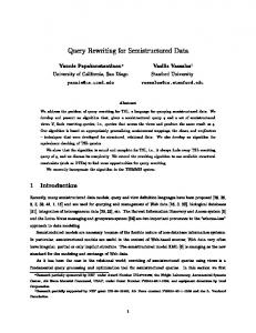
N typei indicates whether the node is the root, an element, text, attribute, processing instruction or comment4 , whereas the label N orderi assumes as value a natural number representing the relative order of the node w.r.t. other children of its parent node, or ⊥ for root, text and attribute nodes. Moreover, the label N contenti can assume PCDATA or ⊥ (undefined) as value. – the cardinality |EL| of the tuple of edge labels is fixed to 1, where the unique label represents the edge type. Each edge ej = !(nh , nk ), ELj ", with nh and nk in N , has a label ELj = !Etypej ", where the label Etypej ∈ {attribute-of, sub-element of}. Note that edges simply represent the “containment” relationship between different items of an XML document and do not have names. In the Plain XML context the following high level constraints hold. In an XML document the root node has type label “root”. Moreover, the content label of element nodes is undefined (as shown in Fig. 10), and the tag label for text nodes is not explicitly specified. Instances of GSMM will then represent specific XML documents. Also, a specific XML graph can be readily computed from the text serialization of an XML document. Concise representation by XML graphs allows for data analysis and clustering; however, representing a huge XML document base will likely result in a very high number of XML graphs. XML Infoset While plain XML is still used for many applications, the XML standard data model, called Infoset [20], is not a text-based one. Rather, it represents both XML schemata and documents as multi-sorted trees, i.e. trees including nodes (called information items) belonging to a variety of types. In other words, an XML document’s information set consists of a number of information items; the information set for any well-formed XML document will contain at least a document information item (the root of the tree) and several others. An information item is an abstract description of some parts of an XML document: each information item has a set of associated named properties5 . The Infoset tree of the document in Fig. 11 is pictorially represented in Fig. 12. The Infoset defines three content models for XML elements: the elementonly content model, which allows an XML tag to include other elements and/or attributes, but no text, the text-only content model, allowing a tag to contain text and attributes only, and the mixed model, allowing a tag to contain both sub-elements and text. The latter model, though still used in some document processing applications, is deprecated for XML-based formats in other domains. For the sake of conciseness only a few of the Infoset properties will be taken into account here; extension to the total Infoset is however straightforward. An XML Infoset graph is a semistructured rooted data graph !N, E, r", obtained as an extension of a Plain XML graph. In particular: 4
5
Plain XML documents may also contain ENTITY nodes, not unlike macro calls that must be expanded before parsing. We do not consider ENTITY expansion in this paper. In the Infoset specification, property names are shown in square brackets, [thus]. We do not follow this convention in this paper.
computer
model
maker
plant
modelname
Toshiba
year
serialcode 12303B
Satellite Pro 4200
A versatile laptop computer product, suitable for use with several operating system
2001
address
description
Osaka, Japan
Fig. 12. The Infoset tree for the document of Fig.11
– the cardinality |N L| of the tuples of node labels is 6. Each node ni has as tuple of labels N Li the corresponding labels of the Plain XML representation plus the two labels U RIi , representing the resource identifier attached to that node, and N amespacei , representing the node namespace. – the cardinality |EL| of the tuples of edge labels is 1, where the unique label represents the edge type as in Plain XML. r ∈ N is the root of the graph. Here an analogous constraint also holds, as shown in Fig. 15. Moreover, we add a high-level constraint (see Fig. 14) that imposes the edge type on the basis of the node type. In fact, in an XML document “sub-element of” edges point to “element” and originate from “element” nodes, whereas “attribute-of” edges originate from “element” and point to “attribute” nodes. In the Infoset terminology, this is informally stated by requiring that the children property of an element item contains either elements or attributes, while attribute items cannot have a children property. In the Infoset context, simple nodes, i.e. nodes with a concrete atomic value, are attribute and text nodes. In fact, the content of an attribute node is its value, whereas the content of a text node is the text itself. We could add also the restriction imposing that these nodes do not have a tag.
{ E_TYPE = AttributeOf −> TYPE1 = element E_TYPE = SubElementOf −> TYPE1 = element
TYPE2 = attribute, TYPE2 = element }
Fig. 14. In the XML Infoset the edge type depends on the type of the endpoint node.
XML Schema Although XML information can be treated as schema-less, purely semistructured data, the notion of XML Schema is increasingly used to represent sets of instances sharing the same structure. An XML Schema is an XML document complying to a standard structure, itself expressed as a schema; for example a schema’s root node has always the label “schema” and may have a child of type namespace[19]. Our representation of XML schemata is twofold: – An XML schema is a low-level constraint that identifies a set of instances. – An XML schema is itself an XML document; as such, it is represented as in Sect 3.1, and must satisfy a suitable set of low level constraints.
This approach provides a simple and effective way to characterize XML schemata and all their instances a-priori. Specifically, an XML graph representing a schema must satisfy, for example, the low-level constraints shown in Figs. 15 to 20.
{ NS1 =
TAG1 = schema
TYPE1 = root }
Fig. 15. The root of the graph has as type root and as tag schema
< E_TYPE >
{ TYPE2 = element −> TAG2 = attribute type V TAG2 = element type V TAG2 = description }
Fig. 16. The root’s children are element nodes (i.e. their type is Element) with label Element Type, Attribute Type, or Description
3.2
Flexible XML
In this section we apply our high level data model to the context of blind queries on semistructured data and more specifically to XML documents, to represent the model of [13]. There, we use a weight to represent the estimated importance of information, thus we add a weight to the arcs of an XML graph and obtain a fuzzy labeled graph. A fuzzy labeled graph is a semistructured rooted data graph !N, E, r" obtained as an extension of a Plain XML graph. where:
Fig. 17. Root must have an attribute with tag xmlns as child
{ TYPE1 = root V TYPE1 = element }
Fig. 18. Each element node (i.e. a node with label Element Type) is a child of either the root, or another element node
{ TYPE1 = root V TYPE1 = element }
Fig. 19. Each attribute node is a child of either the root, or an element node
Fig. 20. Each Attribute Type node is a leaf
– the tuple of node labels is the same as specified for Plain XML graphs. – the cardinality |EL| of the sets of edge labels is 2. Each edge ej = !(nh , nk ), ELj ", with nh and nk in N , has two labels ELj = !Etypej , Eweightj ", where Etypej ∈ {attribute-of, element-of}, and the label Eweightj ∈ [0, 1]. Note that Plain XML graphs do not have weights on edges. The high level constraints mentioned for Plain XML instances must hold also in this context. In Fig. 21 we show an example of a low level constraint imposing that the weight label is greater than 0.3.
{ E_WEIGHT > 0.3 }
Fig. 21. Weights on edges must be greater than 0.3
3.3
The Object Exchange Model
The Object Exchange Model (OEM) [17] is a well known graph-structured data model where the basic idea is that each object has a label that describes its meaning. The OEM model represents semistructured data by means of graphs where nodes denote objects or values and edges represent relationships between objects, in particular an OEM graph is a directed labeled graph where the edge labels describe the pointed nodes. An OEM graph is a semistructured rooted data graph !N, E, r", where: – the cardinality |N L| of the sets of node labels is 3. Each node ni = !OIDi , N typei , N contenti " has an object identifier OIDi ∈ UID, and the node type N typei ∈ { root, object }. – the cardinality |EL| of the tuple of edge labels is 1, and each edge ej = !(nh , nk ), ELj " with nh and nk in N , has a label ELj = !EnodeN amej ", where EnodeN amej is actually the name of the pointed node nk . Again, r ∈ N is the root of the graph, and the root node has type “root”. Consequently, an OEM graph must satisfy the high level constraints in Figs. 22 and 23.
{ TYPE2 = ROOT }
Fig. 22. A node without ingoing edges must have type root
{ TYPE2 = object }
Fig. 23. Each node with an ingoing edge has as type object
3.4
The WG-Log Model
The WG-Log data model [9] was developed for structuring and querying WWW data. WG-Log is a graph-oriented description and query language specifically designed for the needs of Web sites. Based on the graph query language GLog [18], WG-Log was extended to include some standard hypermedia design notations, thus allowing to express model entities and relationships as well as navigational concepts. WG-Log instances are depicted as directed labeled graphs, whose nodes represent objects, while the edges indicate relationships between objects. The details of the WG-Log language can be found in [12]; for our purposes we only recall that two main node types exist, respectively indicating simple objects, or slots (those with an atomic, perceivable value as strings, numbers) and abstract objects, or entities (the ones whose properties are described by means of aggregates of simple objects, e.g. a car, a person etc). Moreover, there are other kinds of nodes to describe indexes and entry points, useful for the representation of the hypermedia structure. Graph edges can denote both logical and navigational relationships, the former having a label indicating the relationship name. A WG-Log graph is a semistructured rooted data graph !N, E, r", where: – the cardinality |N L| of the sets of node labels is 4, where each node ni has the set of labels N Li = !OIDi , N typei , N namei , N contenti ", where the label N typei ∈ {entry point, index, complex node, atomic node }. – the cardinality |EL| of the tuple of edge labels is 2, and each edge ej = !(nh , nk ), ELj " with nh and nk in N , has a label ELj = !Etypej , Enamej ", where Etypei ∈ {navigational, relational, double }. A WG-Log graph must satisfy some high-level constraints. Among these, we represent the constraints in Figs. 24, 25, and 26.
{ TYPE2 = entry point }
Fig. 24. The root of the graph has as type entry point
{ TYPE1 = index −> (E_TYPE = navigational E_NAME =
)}
Fig. 25. From index nodes start only navigational edges which do not have a name label
{ CONTENT1 =
TYPE1 = simple node }
Fig. 26. Each leaf node of the graph has type simple
The representation of OEM and WG-Log by means of our general data model highlights the fact that the OEM syntax does not allow the expression of edge semantics: it is not possible to consider relationships different from the “containment” one, navigational and presentation-related concepts, which are very useful in the representation of Web sites. 3.5
Time
In this section we apply our high level data model to the context of temporal applications (see for example TGM [16]) for representing semistructured data dynamics. In this case we use a time interval to represent when an object exists in the reality or in the database.
Name
Mega Book Store
Name J.K.Rowling
Price
Title
$ 7.99
Harry Potter and the Prisoner of Azkaban
Fig. 27. A simple TGM instance
A semistructured temporal graph is a semistructured rooted data graph !N, E, r", where: – the cardinality |N L| of the sets of node labels is 5, where each node ni = !OIDi , N namei , N typei , N contenti , N timei " has an object identifier OIDi ∈ UID, the node name, the node type in {complex, simple}, a time interval N timei ∈ V ∪ {⊥}, where V is a set of time intervals, and the node content. – The cardinality |EL| of the sets of edge labels is fixed to 3, where each edge ej = !(nh , nk ), ELj ", with nh and nk in N , has three labels ELj = !Enamej , ET ypej ,
Etj ", where ET ypej ∈ {relational, temporal} is the type of the edge, and the last one Eti ∈ V is the time interval representing the valid time. Among others, instances of semistructured temporal graphs must satisfy the high level constraints in Figs. 28 to 31.
{(I=
)}
Fig. 28. Simple nodes do not have a time interval
{ TYPE1 = complex }
Fig. 29. Simple nodes are leaves
In Figure 32 we show a portion of a semistructured temporal graph containing information about books and authors. Note that this labeled graph satisfies the high level constraints described above. Once an instance of a semistructured temporal graph has been constructed, low level constraints may be applied to check static or dynamic properties. For example, with the constraint of Fig. 33 on the instance of Fig. 32 we could check if the time interval of a Book starts after the time interval of its Author. Note that, in general, the time interval of a relationship is not connected to the time interval of the related objects. If we represent valid time in the real world, the constraint above must be added because it gives semantics to the “Writes” relation: a book can become valid only after its author was born!
{(E_NAME = HasProperty)}
Fig. 30. Edges pointing to simple nodes are named “Has Property”
{E_NAME =
E_I =
}
Fig. 31. Temporal edges do not have a name, neither they have a time interval
Fig. 32. A portion of a GSMM graph for a Bookshop temporal database
{ t3 > t1 }
Fig. 33. A low level constraint on time
3.6
Parameters
Instantiation parameters shown in Table 1 are the cardinality of node labels (named |N L|), the cardinality of edge labels (named |EL|), the domain of node labels (named Node Label Domain), and the domain of edge labels (named Edge Label Domain), for the six concrete models described above6 . By inspecting Table 1, we can carry out fast “a-priori” comparison of the models. For example, OEM only distinguishes two kinds of nodes, while OEM edges are labeled with a single label (actually, this label corresponds to the name of the pointed node, and edges represent the containment relation). The XML Infoset is quite similar to OEM, though it has a wider repertoire of node types and uses an enumeration type rather than a generic string for the edge label value. Intuitively, a model that uses enumeration values as edge labels can support design rules, saying when attribute rather than element containment should be used. Note that an enumeration type for edge values is also used in WG-log; this feature is common to Web-oriented models where values of the edge label in the concrete model correspond to different navigation mechanisms (e.g., hypertext link or text inclusion) in the instance data. Moreover, note that all the XML-based models represent order between node children, while OEM, WG-Log, and TGM do not. Plain XML is the one model that does not provide object identifiers.
4
Inter-model translation
The meta-model proposed in this work can be used for inter-model comparisons and translation as well. In particular, given two or more concrete models expressed by means of the GSMM formalism, we would like to be able to translate instances from one model to another one. The translation task is mainly based on the following steps: 6
For the sake of conciseness Table 1 does not explicitly consider Base Types, because they may be very large.
Table 1. Instantiation of meta-model parameters for some concrete models Concrete |N L| |EL| Node Label Model Domain OEM 3 1 OIDSet × {root, object}× (OEM BaseT ypes ∪ {⊥}) Plain 4 1 T agSet × {root, attribute · · ·}× XML N ∪ {⊥} × (P CDAT A ∪ {⊥}) XML 6 1 U RI × N ameSpaceSet × T agSet× Infoset {root, element, text, attribute · · ·}× N ∪ {⊥} × (XM LBaseT ypes ∪ {⊥}) Flexible 4 2 T agSet × {root, attribute · · ·}× XML N ∪ {⊥} × (P CDAT A ∪ {⊥}) WG-Log
4
2
TGM
5
3
OIDSet × {complex, slot, index, entrypoint} × N odeN ameSet× (W G − LogBaseT ypes ∪ {⊥}) OIDSet × N odeN ameSet× {complex, simple}× (T GM BaseT ypes ∪ {⊥}) × V
Edge Label Domain N odeN ameSet {subelement − of, attribute − of } {subelement − of, attribute − of } {subelement − of, attribute − of }× [0,1] {relational, navigational, double}× EdgeN ameSet EdgeN ameSet× {relational, temporal}× V
– for each node and edge label of the source model, try to find a corresponding label in the destination model. Whenever this basic translation is not possible, try to express each node or edge label of the source model, which does not have a corresponding label into the destination model, with a construct (e.g. a label, an additional node or edge) available in the destination model. – to each label of the destination model that is not useful to express components of the instances of the source model assign an undefined value. Now we show how our technique can facilitate the inter-model translation process by considering TGM and plain XML as examples of concrete models. 4.1
Translating TGM into XML
Suppose we have a TGM instance G, let us translate it into the proper GSMM graph G = !N, E, r". In order to obtain another GSMM graph G! = !N ! , E ! , r! " related to an XML document, which represents the information originally contained in G, we have to apply some simple primitives represented in Figure 34: 1. for each n ∈ N , with n = !oid, name, type, te, content", transform it in a subtree of G! composed by three nodes n1 , n2 , and n3 . The first node n1 has as tag label name, as type label root if n = r, element otherwise, an undefined order label, and content as content label (note that content is a defined value only for simple nodes of the TGM graph). The two children of n1 , named n2 and n3 has the labels !id, attribute, ⊥, oid" and !temporalelement, element, ⊥, te", respectively. Note that the edge connecting n1 to n2 is labeled attribute − of , whereas the edge from n1 to n3
is labeled subelement − of . Moreover, we do not use the order label of the Plain XML because TGM does not consider an order relation between the children of a given node. 2. For each edge e = !(m1 , m2 ), ELe " ∈ E, with ELe = !name, type, te", we transform it into a subtree of four nodes n1 , n2 , n3 , and n4 . The node n1 is an element with tag edge2m2 7 (and undefined order and content labels) which has three children: n2 is an element which has as tag temporalelement and as content te, n3 is an attribute with tag edgetype and value type, n4 is an attribute with tag edgename and value name. 3. In general TGM instances are modeled as DAGs whereas XML documents can be represented in a graphical way by means of trees. The third primitive of Figure 34 is introduced in order to solve this distinction between the two concrete models we are considering. If the original graph G contains a node n (or more than one node) with more than one ingoing edge, we translate one path to n as explained in the previous two steps, and we consider all the other edges to n as elements with an idref attribute whose value is the object identifier of the pointed node.
An algorithm for translating TGM into XML code The above considerations allow us to formalize a depth-first algorithm for translating a TGM graph represented with the GSMM formalism into plain XML code. TGM2XML(set of nodes N, set of edges E, node r) { for all nodes n in N paint n white TGM2XMLCODE(N,E,r) } TGM2XMLCODE(set of nodes N, set of edges E, node n) { paint n grey if (n = is a complex node) { write:‘‘ t ’’ for all outgoing edges e_i=((n,x_i),) pointing to a white node x_i { write:‘‘ Et_i ’’ TGM2XMLCODE(N,E,x_i) write:‘‘’’ 7
An edge pointing to m2 .
Node Translation
} for all outgoing edges e_i=((n,x_i),) pointing to a black node x_i { write:‘‘ Et_i ’’ write:‘‘’’ } paint n black write:‘‘’’ } else { write:‘‘ contentvalue ’’ if (n has a temporal outgoing edge to x_j) write:‘‘ ’’ write:‘‘’’ paint n black } } Consider the TGM instance reported in Figure 27 and its translation into the GSMM formalism of Figure 32. The XML code produced by the function TGM2XML is the following: [01/01/1980,now) [01/01/1980,now) Mega Book Store [01/01/1980,now) [01/01/1980,now) [01/01/1990,now) [01/01/1990,now) [01/01/1990,now) J.K. Rowling
[01/01/1999,now) [01/01/1999,now) 7.99 [01/01/1999,now) Harry Potter and the Prisoner of Azkaban [01/01/1999,now) Note that the element Edge2Book has and idref attribute, because the node labeled Book in the graph of Figure 32 has two ingoing edges. We have developed a Visual Basic tool for translating TGM graphs into XML documents and viceversa. Figures 35 and 36 show a running example: the textual representation of a TGM graph reporting information about Books (Fig. 35) is translated into an XML document (Fig.35). Figures 37, 38, and 39 show the reverse step: the XML document about Books which is produced by the previous translation (Fig. 37) is coded into a TGM graph (Fig. 38). Figure 39 shows the final TGM graph.
5
Related work and Conclusions
We have presented a graph based meta-model (GSMM) and a language (GSL) aimed at bringing semistructured data model properties into a unified framework. As for future work the GSM meta-model will be applied to specify ontologies modeling different kinds of concepts. Our meta-model’s main applications are inter-model comparison and translation, fundamental toward easy mediation between heterogeneous data sources. A related though distinct line of research is followed in [2], where authors propose a unified framework for the management and the exchange of semistructured data, described according to a variety of formats and models. In particular
Fig. 35. A tool for translating TGM graphs into XML document
Fig. 36. The XML translation of a TGM graph
Fig. 37. A tool for translating an XML document into a TGM graph
Fig. 38. The TGM graph has been computed
Fig. 39. The visualization of the resulting TGM graph
they consider various schema definition languages for XML, OEM and a model to store Web data, and show that the primitives adopted by all of them can be classified into a rather limited set of basic types. On these basic types, they define a notion of “meta-formalism” that can be used to describe, in a uniform way, heterogeneous representations of data, and give the definition of an effective method for the translation between heterogeneous data representations. The main difference between this proposal and our meta-model is related to schemata: [2] focuses on schemata translation assuming that a schema is available for each data source, whereas we do not require to have the schema in advance, but rather consider schemata as constraints that can be specified with our unified formalism as well (only if needed). In [15] the authors define the Hypergraph Data Model (HDM), a very simple low level modeling language which is based on a hypergraph data structure together with a set of associated constraints. Here the constraint specification language is not formalized; the authors define also a small set of transformations as schemata expressed in HDM, which are used for inter-model transformation. The main difference between this proposal and our meta-model is related to schemata translation. Our work focuses on semistructured data and thus we do not consider schemata translation, but provide a very general graphical formalism allowing the representation of different aspects of data in the semistructured context. Rather, our inter-model translation, as shown by example in Sect. 4, relies on the generality of nodes and edge labels, which can be specialized to the labels allowed by the source and destination models. Moreover, while the Meta-Model of [15] provides some basic primitives whereof the basic constructs of models can be built, our Meta-Model provides a high level, general formalism whose specializations are the models themselves. Other works related to inter-model translation, that do not propose a unifying meta-model but focus on the possibility to translate information from a model to another are [3], [4], and [14]. In [3] the authors provide a generic framework that can be used to merge models in different contexts. In [4] the authors propose an approach to represent, in a uniform way, information coming from different model-based applications. In this work they use RDF and provide a mapping
formalism for inter-model translation. In [14] the authors do not propose a metamodel, but a reference model composed by the relational model and some objectoriented features that are useful to describe the contents of information sources. Dealing with semistructured data the computer scientist is faced with the contrasting requirements of dealing flexibly, but at the same time precisely, with data whose structure is not easily captured by traditional approaches. The use of GSMM and GSL marks a step forward toward a flexible yet complete treatment of the fundamental issues of semistructured data modeling and querying. For example, GSMM provides the means for a posteriori schema derivation and definition: intuitively, a schema represents an instance if it contains its skeleton while disregarding multiplicities and values. Given a semistructured instance, we can represent its schema by drawing a constraint that defines the structure of the document [10]. In particular the constraint specifies, by means of firstorder formulae, all the possible paths starting from the root node, and sets also the admitted labels of nodes and edges. Future work will address such and similar issues, and further investigate on the different kinds of constraints (such as fuzzy, soft, dynamic constraints), together with methodological considerations on their best application contexts. Another line of investigation concerns the use of GSL as a language for those models where no language was defined. As an example, consider UML: here, schemata (models, in UML notation) may be specified by means of different notations, at different levels of details (e.g. class diagrams). A specification based on GSMM could allow the expression of constraints to be associated to a UML class diagram or to any UML diagram. Moreover, constraints expressed in GSL may easily be transformed from more general to more specific representations of the same information by means of different UML notations.
References 1. S. Abiteboul. Querying Semi-Structured Data. In Proceedings of the International Conference on Database Theory, volume 1186 of Lecture Notes in Computer Science, pages 262–275, 1997. 2. P. Atzeni and R. Torlone. A Unified Framework for Data Translation over the Web. In Proceedings of the 2nd International Conference on Web Information System Engineering, pages 350–358. IEEE Computer Society, 2001. 3. P. A. Bernstein and R. Pottinger. Merging Models Based on Given Correspondences. Technical Report UW-CSE-03-02-03, University of Washington, February 2003. 4. S. Bowers and L. Delcambre. Representing and transforming model-based information. In Proceedings of Int. Workshop on the Semantic Web at the 4th European Conference on Research and Advanced Technology for Digital Libraries (SemWeb), 2000. 5. P. Bunemann, W. Fan, J. Sim´eon, and S. Weinstein. Constraints for Semistructured Data and XML. SIGMOD Record, 30:47–54, 2001. 6. P. Bunemann, W. Fan, and S. Weinstein. Path constraints on semistructured and structured data. In Proceedings of 17th Symposium on Principles of Database System, pages 129–138. ACM Press, 1998.
7. S. S. Chawathe, S. Abiteboul, and J. Widom. Representing and Querying Changes in Semistructured Data. In Proceedings of the Fourteenth International Conference on Data Engineering, pages 4–13. IEEE Computer Society, 1998. 8. S. S. Chawathe, S. Abiteboul, and J. Widom. Managing historical semistructured data. Theory and Practice of Object Systems, 5(3):143–162, 1999. 9. S. Comai, E. Damiani, R. Posenato, and L. Tanca. A Schema-based Approach to Modeling and Querying WWW Data. In Proceedings of the Third International Conference on Flexible Query Answering Systems FQAS’98, volume 1495 of Lecture Notes in Computer Science, pages 110–125, 1998. 10. A. Cortesi, A. Dovier, E. Quintarelli, and L. Tanca. Operational and Abstract Semantics of a Query Language for Semi–Structured Information. Theoretical Computer Science, 275(1–2):521–560, 2002. 11. E. Damiani, B. Oliboni, E. Quintarelli, and L. Tanca. Modeling semistructured data by using graph-based constraints. In OTM Workshops Proceedings, Lecture Notes in Computer Science, pages 20–21. Springer-Verlag, Berlin, 2003. 12. E. Damiani and L. Tanca. Semantic Approches to Structuring and Querying Web Sites. In Procedings of 7th IFIP Working Conference on Database Semantics (DS97), 1997. 13. E. Damiani and L. Tanca. Blind Queries to XML Data. In Proceedings of 11th International Conference (DEXA 2000), volume 1873 of Lecture Notes in Computer Science, pages 345–356, 2000. 14. A. Y. Levy, A. Rajaraman, and J. J. Ordille. Querying heterogeneous information sources using source descriptions. In Proceedings of the Twenty-second International Conference on Very Large Databases, pages 251–262, Bombay, India, 1996. VLDB Endowment, Saratoga, Calif. 15. P. McBrien and A. Poulovassilis. A uniform approach to inter-model transformations. In Conference on Advanced Information Systems Engineering, pages 333– 348, 1999. 16. B. Oliboni, E. Quintarelli, and L. Tanca. Temporal aspects of semistructured data. In Proceedings of The Eighth International Symposium on Temporal Representation and Reasoning (TIME-01), pages 119–127. IEEE Computer Society, 2001. 17. Y. Papakonstantinou, H. Garcia-Molina, and J. Widom. Object Exchange Across Heterogeneous Information Sources. In Proceedings of the Eleventh International Conference on Data Engineering, pages 251–260. IEEE Computer Society, 1995. 18. J. Paredaens, P. Peelman, and L. Tanca. G–Log: A Declarative Graphical Query Language. IEEE Transaction on Knowledge and Data Engineering, 7(3):436–453, 1995. 19. World Wide Web Consortium. XML Schema, 2001. http://www.w3C.org/TR/xmlschema-1/. 20. World Wide Web Consortium. XML Information Set, 2001. http://www.w3C.org/xml-infoset/. 21. World Wide Web Consortium. Extensible Markup Language (XML) 1.0, 1998. http://www.w3C.org/TR/REC-xml/.