Modeling Web Systems using SDL Joe Abboud Syriani and Nashat Mansour Computer Science Program, Lebanese American University P.O. Box: 13-5053, Beirut, Lebanon E-mails:
[email protected],
[email protected]
Abstract. We propose modeling the architecture of web systems using the Specification and Description Language (SDL), which is a formal language. SDL is shown to be quite convenient for modeling features of web systems such as hyperlinks, sending and receiving data, and client-server communication. Hence, it facilitates our understanding of web applications. Further, we describe how to test web systems, based on the SDL model, in order to ensure that the implementation conforms to the specification.
1
Introduction
Using web technologies, users can access other documents or data from other servers by sending requests. A client sends a request using a browser and the server responds to the client with the document or data needed. A web system incorporates a web server, network connection, client browser, and a web application. A client browser navigates and renders a web page that can be considered as a document page related to other pages (via hyperlinks) and objects (Database, DOM, etc…). A web application is a client/server software that uses an HTML/XML browser for one or more clients communicating with a web server via HTTP and an application server managing business logic [1]. Web Applications are becoming more complex. Complexity arises due to several factors, such as large number of hyperlinks, communication, interaction, and distributed servers. To manage complexity, web systems are modeled. Modeling allows a software engineer to specify, understand and maintain the architecture of web application more effectively. The Unified Modeling Language (UML) has been used for modeling web applications. Conallen [2] has proposed an extension to the UML that is designed so that web-specific components can be integrated with the rest of the system model, and to exhibit the proper level of abstraction and detail suitable for designers, implementers, and architects of web applications. Kaewkasi and Rivepiboon [3] have also proposed using UML and use case maps to model web applications. In this paper, we explore the use of the Specification and Description Language (SDL) [4] for modeling the architecture of web systems; SDL is usually used for modeling communication systems. The SDL model allows us to use existing implementation code of SDL specifications. We also propose an improvement to the existing SDL implementation. Further, the model allows us to use existing SDL based techniques for testing and verifying that the implementation conforms to the specification. To demonstrate this advantage, we have used the Testing and Test Control Notation [5].
2
Background on SDL
Specification and Description Language (SDL) is used for formal specification and design of systems. It supports reactive, concurrent, real-time and distributed systems [4,6,7]. SDL can be described in terms of its structural and behavioral concepts. The structure of SDL is divided into agents and communication. Agents are composed of systems, blocks and processes, whereas communication is composed of channels and gates. An agent is an extended finite communication state machine that has its own identity, its own signal input queue, its own life cycle and a reactive behavior specification. Three main parts exist on agent declarations: attributes, behavior, and internal structure. System is the entry point of the SDL specification. It includes a set of blocks and channels. Blocks are connected to each other and to environment by channels. A block can contain either a set of processes or a set of block substructures. Processes are used to specify the behavior of the system. Variables store data local to an agent and they are owned by the agent’s state machine. They can be private, local, or public. Communication is based on signal exchanges that carry the signal name, user data and sender identification. It requires a complete path from sender to receiver that consists of channels, gates and connections. Finite state machines describe the behavior of an agent. They consist of states that represent a particular condition in which an agent may consume a signal and transitions that represent the sequence of activities triggered by the consumption of the signal. They are called processes in SDL. A state machine is either in a state waiting for a signal or performing a transition. A transition results in entering a new state or stopping the agent. SDL processes communicate with each other and with the environment by exchanging signals. Each process instance in SDL owns a dedicated input port that allows received signals to be queued until they are consumed or discarded by the process instance owner. SDL supports modeling of non-determinism for transitions, postponing signals, and conditions signals. A Message Sequence Chart (MSC) describes a specific execution sequence of the system [4]. It shows how messages are passed between the instances. Instances are described by vertical lines that define the temporal ordering of the events related to the instance. An instance represents an SDL block, process or service. Messages represent the interaction between instances or between an instance and the environment. The message is described by a horizontal arrow. Conditions in MSC represent a notion of state, which is represented by a hexagon. An action in MSC is represented by a rectangle and it describes an internal activity of the instance.
3
Modeling Approach
In this section, we describe how SDL can model the main features of the architecture of web applications. These features include: pages, hyperlinks, behavior of the web page on the client side and the server side, and client-server and distributedserver communication. Furthermore, the SDL model allows us to use existing implementation code of SDL specifications and this enables us to use also existing techniques and schemes in SDL for testing and verification [4]. The SDL model of a web application represents all the web pages of the system and their relationships with each other. Each web page is represented by an agent and
the hyperlinks between pages are represented by signals. A hyperlink in a Web application represents a navigational path through the system. This relationship is represented in the SDL model with a signal sent through a channel association. The signals may contain parameters. For example, such parameters may contain user name and passwords that are sent within the signals to logon to a server. This link association originates from a client page and points to either a client or a server page. The procedure embodied in both the client and the server can be modeled using composite states. This is done by modeling the transition from one state to another in order to control the internal procedures of both the client and the server. These steps may contain input signals, output signals, procedure calls, etc… A Message Sequence Chart can be used to model the sequence steps of moving between agents or states. We note that this model helps in verifying the consistency of a web application specification with its requirements. If a client is accessing a server, a communication signal is fired. Upon receiving this signal, the server should reply back with another signal. The contents of this signal can also be specified. By modeling this system using SDL, we can ensure that this communication is working correctly. This also can be done from one server to multiple servers i.e. hyperlinks, database query, etc…. This feature makes SDL more powerful in comparison with UML, as UML has its strengths in the early phases of software engineering because of its semi-formality; SDL has its advantages mainly in the design phase and subsequent phases [8].
4
Example
We illustrate our modeling approach using a simple web site example that enables a user to login and check his/her account balance. We include only some essential graphical diagrams and omit the textual representation due to space limitation. We assume that the system is built from a client browser and a web server that includes the database. The user can do any of the followings: create a new account, login, logout, or check the account balance. The server will respond to each of these requests by a confirmation, an error, or a variable containing the account balance. In the following subsections, we model the blocks, processes and message sequence charts. 4.1
Blocks
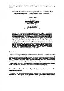
We have two blocks: Client and Server. The block client has two processes: client_manager process that deals with the creation management and client_login that deals with the clients that login. The block server has similar processes. The graphical representation of only the server blocks is given in Figure 1. Note that the channel ch_server_local has only one direction and it contains no reply or feedback. Also, the create_error message is sent from the server manager to the server login in case an error occurred.
[ create_request ]
Block server
ch_server_manager
server_manager create_confirm, create error ch_server_local login_request, logout_request, balance_request
[ create_error ]
ch_server_login
server_login(0,100) login_confirm, logout_confirm, balance_reply, login_error Fig. 1. Graphical representation of the Block server
4.2
Processes
Four processes are derived from the two blocks: client login, client manager, server login and server manager. The client_login process is represented by a finite state machine. It can be in any of the two states: active and idle. Procedures are first declared in the process. The graphical representation of the client login process is given in Figure 2. The client receives a reply from the server: whether the login was successful or not, a logout confirmation, or the balance. When any of these messages are received, the client runs a procedure that mainly contains an HTML file to be rendered by the client browser. The client_manager process is also represented by a finite state machine. It can be only in one state: idle. One Procedure is declared in this process: user_create_error. This procedure will send an HTML page to the client informing it about a creation error. The client manager can receive a message that creation is done successfully or with error. It can also receive a message that the login failed. If the message is a create confirmation, an output signal about the login confirm is sent to the output. If the message is a login error, a message is sent to the output that a creation is needed. The graphical representation of the client manager process is given in Figure 3. Serve_login and server_manager processes have similarities with those of the client side and are omitted for brevity. 4.3
Message Sequence Chart
Message Sequence Charts (MSC) are used to represent the different requests. In our example, there are four main requests: create request, logout request, login request, and balance request. For brevity, we consider only the login request.
In the login request module, two processes exist: the client login and the server login. The create request module accepts the user request only if the client login and the server login are in the idle state. Then, there is an internal action within the server login to check if the account exists. If it does not exist, the state of the server login remains idle and a login error output will be sent to the client login. If the account exists, the state of both client login and server login becomes active and a login confirmation is sent to the client login and the client login sends to the browser that the client is logged in. The login request MSC is shown in Figure 4 (ignoring the time information which is used in the next section).
Process client_login
idle
login_confirm
user_login_error
user_login
balance_reply
user_logout
login_error user login error
user login active
idle active
logout_confirm
balance_reply
user logout
balance reply
idle
active Fig. 2. Graphical representation of the client login process
Process client_manager
user_create_error
idle
create_confirm
login_confirm
client_login
create_error
login_error
user create er
create_request
idle
idle
active Fig. 3. Graphical representation of the client manager process
msc login_request_mod Client login (user)
user request (2s, 5s)
Server login (SUT)
idle login_request get account find
t1
login_error
idle
active login_confirm client_login
Fig. 4. Login request MSC (includes timers for testing)
5
Testing
In this section, we demonstrate that based on the SDL model of a web system, we are able to generate test cases to verify that the implementation conforms to the specification. We use the existing Testing and Test Control Notation (TTCN) [5]. We have also added timers to our test cases in order to control and measure the response time. We give only one example that shows how to use TTCN-3 to test the login request module. Figure 4 shows a modification to the MSC representation of the login request by adding time. We have added a time interval where the start event is a send to the server and the end event is a receive from the server. Since two time points are needed, we declare two TTCN timers: t-check_min and t_check_max. In addition, t1 measures the time taken between sending the message and receiving the response. The TTCN-3 code for testing the login request is shown in Figure 5. In this test case, we check the following: if the minimum or maximum time is timed out, the test fails; if the client receives the response of either login_confirm or login_error that satisfies the specification of the web application and within the time interval, the test passes; in case other responses are received, nothing happens until time out.
6
Extending SDL implementation for web systems
SDL basics have been implemented for protocols. The implementation comes with different solutions for the process management and the buffer management [4]. In this section, we propose an improvement to the existing SDL implementation that is relevant for web systems. Since Web design contains a lot of communication between clients and server(s), a lot of signals are transferred and the server may be busy and might not respond immediately. This issue can be addressed by either minimizing copy operations or by optimizing the process management. Usually when a signal is sent from one process to another, it is copied to the output queue and waits for the input queue of the receiver to release it. We use buffer management to alleviate this problem. The data will be stored on some data queues and the buffer will store the signal identification and related information as well as the reference to the data queues. The buffer stores the data until the transition is finished and it is released to the receiver process instance. One approach to optimize process management in the context of SDL is the activity thread model. The server model exhibits overhead such as that of synchronous operations including queuing. This is not present in the thread control. However, thread control is based on synchronous communication that makes it incompatible with the SDL model. Instead of transmitting signals to the receiving process instance, the procedure implementing the process instance can be called directly. This will merge scheduling with communication. Concerning the internal communication of the active thread, the sequence of the output and the input constructs result in a sequence of procedure calls that is the activity thread. The activity thread is terminated when the event processed by the SDL process is terminated.
timer t_check_min; // minimum time timer t_check_max; // maximum time timer t_measure := 10000; var float t1; client_login.send(login_request) ; t_check_min.start(2); // start the minimum time measurement t_check_max.start(5); // start the maximum time measurement t_measure.start; // start the measurement time alt { [] t_check_min.timeout { // if the minimum time is timed out verdict.set(fail); // test is failed mycomponent.stop;} // stop the component [] t_check_max.timeout { // if the maximum time is timed out verdict.set(fail); // test is failed mycomponent.stop;} // stop the component [] client_login.receive(login_confirm) { vedict.set(pass); // test is passed t1 := t_measure.read; // read the time interval t_measure.stop; // stop the time measure t_check_min.stop; t_check_max.stop;} [] client_login.receive(login_error) { vedict.set(pass); // test is passed t1 := t_measure.read; // read the time interval t_measure.stop; // stop the time measure t_check_min.stop; t_check_max.stop;}
Fig. 5. TTCN-3 code for the login request
7
Conclusion
We have shown how SDL can be used to model web systems. Such modeling allows us to use existing implementation code of SDL specifications. Also, we have demonstrated how to use SDL modeling to test web systems using the TTCN technique.
References 1. Dietel, Dietel, Nieto: E-business & e-commerce how to program, Prentice Hall (2001) 2. Conallen J.: Building Web Applications With UML, Reading, Mass., Addison-Wesley (1999) 3. Kaewkasi, C., Rivepiboon, W.: WWM: A Practical Methodology for Web Application Modeling, Chulalongkorn University, Bangkok, Thailand (2002) 4. Mitschele-Thiel, A.: Systems Engineering with SDL, John Wisley & Sons, LTD (2001) 5. ETSI: Method for Testing and Specification, The Testing and Test Control Notation version 3 (2003) 6. J. Fischer, E. Holz, M. v. Löwis, A. Prinz (2000), SDL-2000: A Language with a Formal Semantics, Humboldt-Universität zu Berlin. 7. International Engineering Consortium (2001), Specification and Description Language (SDL), http://www.iec.org, Telelogic. 8. Schwingenschlogl, C., Schonauer, S.: Application and Service Development using UML and SDL, Technische Universitat Munchen (2000)