INTERNATIONAL JOURNAL of RENEWABLE ENERGY RESEARCH Moualdia Abdelhafidh et al., Vol.2, No.2, 2012
Modelling and Control of a Wind Power Conversion System Based on the Double-Fed Asynchronous Generator A.Moualdia*, MO.Mahoudi**, L.Nezli**, O.Bouchhida*
*LREA, Research Laboratory of Electronics and Automatics, University yahia fares Médéa, Algeria **LCP, LaboratoryofProcessControlDpt. Electrical Engineering, National Polytechnic School, 10, Street Pasteur, El Harrach, Algeria ‡
Corresponding Author; Moualdia Abdelhafidh, INSFP BP 89 Ain d’heb médéa, Algeria,+2130792150261,
[email protected],
[email protected],
[email protected],
[email protected] Received: 11.03.2012 Accepted: 07.04.2012
Abstract-Wind energy has many advantages, it does not pollute and it is an inexhaustible source. However, the cost of this energy is still too high to compete with traditional fossil fuels, especially on sites less windy. The performance of a wind turbine depends on three parameters: the power of wind, the power curve of the turbine and the generator's ability to respond to wind fluctuations. This paper presents a control chain conversion based on a double-fed asynchronous machine (D.F.I.G) and flow-oriented. The supply system comprises two identical one converters connected to the rotor (RSC) and the other connected to the network (GSC) via a filter. The architecture of the device (Fig. 1) is up by three commands are necessary for the operation of the turbine control extraction of maximum power of the wind to control itself (MPPT) control of the RSC controlling the electromagnetic torque and stator reactive power and control of the GSC by controlling the DC link voltage and active power and reactive power exchanged with the network. The proposed control, has been validated in both modes of operation of the three-bladed wind 7.5kw, using the Matlab / Simulink. The results of simulation control technology study provide good dynamic performance and static. Keywords-D.F.I.G, Variable wind speed, hypersynchronous, Energy quality, hypo synchronous
1. Introduction The intense industrialization of recent decades and the proliferation of electrical appliances have led to global needs considerable power. Meet this demand, growing today; industrialized countries have overwhelmingly called for nuclear power plants. This energy source has the undeniable advantage of not causing air pollution unlike thermal power plants, but the risk of nuclear accident, treatment and waste disposal are very real problems that make it unattractive to the energy future generations. To address these problems, countries are turning increasingly towards the use of clean energy sources and renewable. Indeed, these countries committed themselves in the medium term, to increase their production of electricity from renewable energy. These renewable energy sources, wind energy are one of the largest and most promising sources of renewable energy worldwide in terms of development. Especially as they are
clean and economically viable. Institutional incentives and government, together with wind energy potential and development of energy conversion technologies have enabled the rapid development of wind energy with an annual growth of 30% and a market penetration of electricity by 12% 2012 [1]. Many researches on wind turbine order were carried out. Thanks to them, the latest generation of wind turbines operate with variable speed and have a pitch regulated [2]. We can thereby change the rotational speed and the pitch angle of each blade, allowing us to improve the production of the turbine. Currently, the variable speed wind energy system based on the double-fed induction machine (D.F.I.G) is the most used in wind farms on land. Its main advantage, not least, is to have its three-phase converters designed for a portion of the nominal power of the DFIG, which makes a significant economic benefit compared to other possible solutions electromechanical conversion (machine permanent magnet synchronous for example). Indeed, the DFIG can
INTERNATIONAL JOURNAL of RENEWABLE ENERGY RESEARCH Moualdia Abdelhafidh et al., Vol.2, No.2, 2012 operate over a speed range of ± 30% around the synchronous speed, thus ensuring a reduced sizing of static converters because they are connected between the rotor winding of the DFIG and the grid [3,4]. In the electromechanical conversion chain of wind turbine systems, static converters voltage three-phase structure are critical because they control the active and reactive power injected to the grid depending on wind speed applied on wind turbine blades. The objective of this paper is to propose a generator control that can optimize the production of the wind in both mode synchronous hyper and hypo that is to say, improve the quality of energy and energy efficiency. The architecture of the device Fig.1 is up by three commands are necessary for the operation of the turbine control extraction of maximum power of the wind to control itself MPPT control of the RSC controlling the electromagnetic torque and stator reactive power and control of the GSC by controlling the direct current Link voltage and active power and reactive power exchanged with the network. Wind DFIG Grid
Gearbox RSC
DC link
GSC Filter
Ω MPPT
CONTROL RSC
CONTROL GSC
Tem_ref
Qs_ref
Vdc_ref
The speed ratio λ is defined as the ratio between the linear speed of the blades and wind speed . 2.2. MPPT Bloc The technique of extraction of the maximum power is to determine the speed of the turbine which provides the maximum generated power. The reference speed of the turbine is that corresponding to the optimum ratio of speed λ_opt = 8.1 (with β constant and equal to 0 °) to obtain the maximum value of (Cp = 0.47). This control structure is to adjust the torque appearing on the turbine shaft so as to fix its speed to its reference written by
Especially, to extract that effectively the power of wind, while maintaining security in the system, the turbine must be operated within the three zones, which connect the wind speed, the maximum permissible rotor, and the desired power (Fig. 3). In zone I, the turbine is stopped because the wind is not strong enough for power generation is costeffective vis-à-vis the operating energy. In zone II operation, the turbine operates at partial load. Here the objective is to maximize fuel efficiency. Thus, the rotational speed changes according to the wind speed so as to remain in the operating point of maximum aerodynamic efficiency. The goal is that the power coefficient is always optimal. Zone III, strong wind, corresponds to full load operation. We must limit the power to avoid damaging the system. To ensure maximum efficiency of the turbine, keep the power factor at its maximum [6-7]. The purpose of the proposed control strategy is to allow the couple wanted to optimize performance is beautiful and well supplied by the induction generator double-fed Tg.
Qg_ref
Fig.1.Architecture of the wind system. 2.
.
Cp
Modelling of Conversion System
Cpmax
2.1. Modelling of the Turbine Mechanical power available on the shaft of a wind turbine is expressed by the relation:
max
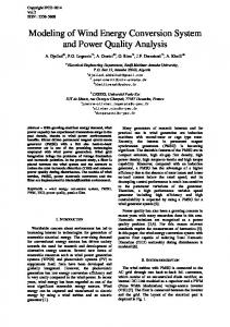
(1) The power coefficient Cp is the aerodynamic efficiency of the wind turbine. It depends on the characteristic of the turbine. The variation of this coefficient as a function of the speed ratio λ and the orientation angle β of the blade [5]. (2) With:
Fig.2. Power coefficient 2.3. Modelling of D.F.I.G The generator chosen for the conversion of wind energy is a double-fed induction generator, DFIG modeling [8, 9] written in the repository of the Park, presented by the system of equations:
C1=0.5176, C2=116, C3=0.4, C4=5, C5=21, C6=0.0068. 301
INTERNATIONAL JOURNAL of RENEWABLE ENERGY RESEARCH Moualdia Abdelhafidh et al., Vol.2, No.2, 2012 (9.d) (9.e)
(3)
Or is the amplitude of the stator voltage assumed constant. From equation (8.e) we can establish that the electromagnetic torque can be controlled directly by acting on the current , so the reference current is: (4)
(10) Equation (7) of the reactive power of the stator becomes:
(5) (11) (6) In the coordinate two-phase, the active and reactive power stator and rotor of an induction generator can be written:
From equation (10), we note that the reactive power of the stator can be controlled by varying the current to guarantee operation at unity power factor set point so the reference current on the axis is:
(7)
(12)
(8)
The control scheme of the converter on the rotor side is illustrated by Figure 4. Grid
Turbine
RSC AC
Gearbox
Wind
DC
Ω𝑟𝑒𝑓
-
Ω𝑔
+ MPPT
Fig.3. Typical curve of the power extracted by a wind turbine according to the wind speed
C𝑒𝑚𝑟𝑒𝑓 SMR
U𝑠
𝑖𝑟𝑎𝑏𝑐
DFIG
𝑉𝑑𝑐
Hysteresis current Controller
2𝑊𝑠 𝐿𝑠
𝑖𝑟𝑞𝑟𝑒𝑓
3𝑝𝑀𝑈𝑠
abc 𝑖𝑟𝑎𝑏𝑐𝑟𝑒𝑓
1 𝑀𝑊𝑠
dq
𝑖𝑟𝑑𝑟𝑒𝑓
Fig.4. Control of the RSC
2.4. Control of Rotor Side Converter RSC The stator flux is aligned with the axis, we assume that the network is stable and the stator flux constant set. Furthermore the generator stator resistance is negligible. [10] Since the stator flux is aligned with the axis we can write and equations (3), (4) and (5) become respectively: (9.a) (9.b) (9.c)
2.5. Grid side converter control GSC The GSC is connected between the DC link voltage and the electrical network via an R, L filter. This converter has two roles: to maintain the DC link voltage constant regardless of the magnitude and direction of flow of the power of the DFIG rotor and maintain a unity power factor at the connection point with the grid. The command of the GSC Fig.5 performs two functions: the control currents flowing through the filter and RL control DC link. [11, 12] The mains voltage can be expressed as follows:
302
INTERNATIONAL JOURNAL of RENEWABLE ENERGY RESEARCH Moualdia Abdelhafidh et al., Vol.2, No.2, 2012
(13)
Using the transformation of the park, equation (13) can be expressed as follows: (14)
respectively from the control block of the DC link and control of reactive power at the connection point of the GSC with the grid. The direct current component is used to control the reactive power network side. The quadrature component, in turn, is used to adjust the DC link voltage. In this regulation the converter is modelled by a gain Gc = 1. Current control 𝐼𝑔𝑑_𝑟𝑒𝑓 +
𝐾𝑝𝑔 +
-
, with
is the amplitude of
𝐼𝑔𝑞_𝑟𝑒𝑓 +
𝐾𝑝𝑔 +
-
voltage. Thus the expressions of active and reactive power are expressed respectively by the following equations: (15) By neglecting the losses of the converter (GSC), the continuous power must be equal to the rated active power network. (16)
Iond Ired
𝐾𝑖𝑔 𝑆
+
-
𝐺𝑐
𝐾𝑖𝑔 𝑆
-
+ 𝐺𝑐
−1 𝑅𝑔 + 𝐿𝑔 𝑆
𝐼𝑔𝑑
+
-
−1 𝑅𝑔 + 𝐿𝑔 𝑆
𝐼𝑔𝑞
2.6. DC Link Voltages Control. Regulating the DC link voltage is then accomplished by an external loop (relative to the inner loop control of current), for maintaining a constant voltage on the DC link, with a PI controller generating the reference current in the capacitor. The Fig. 7 shows the block diagram of the control of the DC link voltage.
𝑃𝑜𝑛𝑑 𝑣𝑑𝑐_𝑟𝑒𝑓 +
vdc
Grid
Rg, Lg
-
Fig.6. Control currents flowing through the filter Rg, Lg
GSC
Ic
+
GSC+Filter
𝑊𝑠 𝐿𝑔 𝑖𝑔𝑑
Ug+𝑊𝑠 𝐿𝑔 𝑖𝑔𝑑
The orientation of the voltage vector we can write: and
𝑊𝑠 𝐿𝑔 𝑖𝑔𝑞
𝑊𝑠 𝐿𝑔 𝑖𝑔𝑞
𝑖𝑐_𝑟𝑒𝑓
PI
𝑣𝑑𝑐
+
𝑃𝑔_𝑟𝑒𝑓
+ 𝑃𝑐_𝑟𝑒𝑓
Igab Vgab
𝑖𝑔𝑞_𝑟𝑒𝑓 Eq 15
𝑃𝑜𝑛𝑑
DC link Eq 19 𝑣𝑑𝑐 1 𝐶𝑠
-
𝑃𝑔
+ 𝑖𝑐
1 𝑣𝑑𝑐
DC link control
6
Fig.7.Control loop of the DC link voltage Génération PWM
Qg_ref
Current control
Igq* DC link control Vdc_ref
Vdc GSC CONTROL
The power used on the DC link can be expressed as follows:
(17)
Iond
Fig.5. The principle of the converter control GSC. These powers are related by: 2.5.1. Control currents flowing through the filter The model of the binding of GSC network in the frame following the dq stator rotating field shows us that we can establish control of the currents flowing in the filter given RL, what about the influence of coupling, each can be controlled independently each with its own regulator. The block diagram of the control loops of the dq axes currents is written to Fig. 6 [13, 14]. The markers used are of PI type. In this scheme of regulation of compensation appear terms of dq axes. Currents and references Igd_ref and Igq_ref are
(18) Neglecting all losses to the Joule power exchanged between the rotor of the DFIG and the grid (losses in the capacitor, the converter and filter), we can write: (19) The reference power for the capacitor is related to the reference current flowing in the capacitor.
303
INTERNATIONAL JOURNAL of RENEWABLE ENERGY RESEARCH Moualdia Abdelhafidh et al., Vol.2, No.2, 2012 In fig.7 appears available power corresponding to the power rotor: it's been a disturbance [14, 15] of the regulation and will be compensated in the control chain. 3.
Simulation Results
corresponding to changes in the reference direct current rotor (Figure 8) and also on the rotor reactive power Qr. From time t = 1s we set the stator reference reactive power equal to 4500 Var, again, different reactive powers are properly regulated.
Simulation results were performed using software Matlab / Simulink. To validate the controls proposed in this paper, we present two operating points in hypo-or hypersynchronous fashion. For these simulations, we consider that the wind system is steady and working in the zone of optimal functioning (zone 2), that is to say that it produces maximum power versus speed of the wind. The reference voltage of the DC link is set at 620V. Reactive power is set at Qg_ref 0VAr, ensuring a unity power factor at the connection of the GSC with the grid. By cons, we will vary the stator reactive power Qs playing on its reference value in the control of GSC. 1) Wind synchronous
power
system
operation
mode
hypo
For this mode, a wind velocity equal to 7.5m / s is applied on wind turbine blades, which corresponds to a speed of DFIG in MPPT control approximately 1044 tr/min, a shift 30% hyposynchronous mode, as shown in Figure 8.
Fig. 8. Dc link voltage and generator speed (hypo synchronous) We also observe that the DC link voltage is perfectly regulated to 620V by the GSC. Figure 9 shows the temporal evolution of the various power supply Qs, Ps and Pr, Qr. At time t = 1s, the wind system operates as a unity power factor and reactive power Qs_ref Qg_ref imposed zero. From time t = 1s to t = 3s, we set the stator reactive power reference equal to -4500Var,
Fig. 9. Ps, Qs, Pr, Qr, ird, irq and iar (hypersynchronous) 2) Wind synchronous
power
system
operation
mode
hyper
For this mode, a wind speed equal to 11.5m/s corresponds to the nominal operation of the turbine is applied 304
INTERNATIONAL JOURNAL of RENEWABLE ENERGY RESEARCH Moualdia Abdelhafidh et al., Vol.2, No.2, 2012 on wind turbine blades, which corresponds to a speed of DFIG in MPPT control approximately 1650 tr /min, a shift of -11% hyper synchronous mode, as shown in Figure 10 and Figure 11. The same stator reactive power variations have been applied to this mode as the previous. We also note that the dq axis rotor currents are perfectly decoupled through the decoupling strategy by ensuring natural PWM hysteresis. We also observe the rotor phase current follows perfectly the reference obtained by the orientation of the stator flux. Both modes are validated and independent control of different powers of the wind system.
4.
Conclusion
In this paper, we presented a system for converting wind power (7.5KW) equipped with double-fed asynchronous machines. Initially, we modelled the different components of the wind system. Indeed, aerodynamic and mechanical models of the turbine. Then, in order to establish the different orders of the two converters, we have developed models of the DFIG and the binding of SAG to the network via the RL filter. In this work we have focused the study on the command in zone 2 operation allowing the wind to extract the maximum power available in the wind. The different orders of SAG and CSR were detailed to ensure independent monitoring of active and reactive power while ensuring optimum operation of the wind. Finally, to validate the proposed overall control of the wind system, we performed simulations for two operating points: one mode and the other hyposynchronous hypersynchronous mode. The results obtained showed that the active and reactive power of the wind energy system could be controlled independently while ensuring an optimal active power supplied to the grid regardless of the mode of operation. Acknowledgements
Fig. 10.Dc link voltage and generator speed (hyper synchronous)
The work presented in this publication was carried out in laboratory process control to National Polytechnic School under the scientific direction of Mr. MO. MAHMOUDI professor at the National Polytechnic School Algeria and Mr. L.Nezli teacher conference at the School National Polytechnic Algeria to whom I express my deep gratitude for all the advice and encouragement they provided during my entire duration of the different works, despite their lanky. References [1] S. Peresada, A. Tilli and A. Tonielli, ″Indirect Stator Flux-Oriented Output Feedback Control of a Doubly Fed Induction Machine″, IEEE Transactions on Control Systems and Technology, Vol. 11, No. 6, pp. 875-888, November 2003. [2] Z. X. Fang, X. D. Ping and L. Y. Bing, ″Predictive Functional Control of a Doubly Fed Induction Generator for Variable Speed Wind Turbines″, In Proceedings of the 5th World Congress on Intelligent Control and Automation, Hangzhou, pp. 3315-3319, China, June 1519, 2004. [3] G. Salloum, ″Contribution à la Commande de la Machine Asynchrone à Double Alimentation″, Thèse de Doctorat en Génie Electrique, Institut National Polytechnique de Toulouse, France, 2007. [4] Jun Yao, Hui Li, Yong Liao, and Zhe Chen, Senior Member, IEEE “An Improved Control Strategy of Limiting the DC-Link Voltage Fluctuation for a Doubly Fed Induction Wind Generator, IEEE transactions on power electronics, vol. 23, no. 3, may 2008.
Fig. 11. Ps, Qs, Pr, Qr, ird, irq and iar (hyper synchronous)
[5] R. Thresher et al., “The status and future of wind energy technology,” IEEE Power & Energy Magazine, vol. 5, n°6, pp. 34-46, November/December 2007. 305
INTERNATIONAL JOURNAL of RENEWABLE ENERGY RESEARCH Moualdia Abdelhafidh et al., Vol.2, No.2, 2012 [6] R. Fadaeinedjad et al., “Simulation of a wind turbine with doubly fed induction generator by FAST and Simulink,” IEEE Trans. Energy Conversion, vol. 23, no. 2, pp. 690700, June 2008.
[13] J. Hu and Y. He, “Modelling and enhanced control of DFIG under unbalanced grid voltage conditions,” Electr. Power Syst. Res., vol. 79, no. 2, pp. 273-281, Feb. 2009.
[7] T. Senjyu et al., “Output power levelling of wind turbine generator for all operating regions by pitch angle control,” IEEE Trans. Energy Conversion, vol. 21, n°2, pp. 467-475, June 2006.
[14] P.E. Vidal, Etude Commande Non-linéaire d'une Machine Asynchrone à Double Alimentation, Thèse de Doctorat, INP Toulouse 2004.
[8] P. Poure, S. Saadate, M. Machmoum, “Variable speed DFIG wind energy system for power generation and harmonic current mitigation”, Renewable Energy, Volume 34, Issue 6, June 2009, Pages 1545-1553. [9] A. Gaillard, “Détection de défauts des convertisseurs de puissance à l’aide de FPGA : cas d’un système éolien base sur une Machine Asynchrone à Double Alimentation (MADA)”, Actes de la 8ième Conférence des Jeunes Chercheurs en Génie Electrique (JCGE’08), Ecole Centrale de Lyon, Ecully, France, pp. 202- 207, 16-17 décembre 2008. [10] D. Zhi and L. Xu, “Direct power control of DFIG with constant switching frequency and improved transient performance,” IEEE Trans. Energy Convers., vol. 22, no. 1, pp. 110-118, Mar. 2007. [11] M. I. Martinez, G. Tapia, A. Susperregui, and H. Camblong, “DFIG power generation capability and feasibility regions under unbalanced grid voltage conditions,” IEEE Trans. Energy Convers., vol. 26, no. 4, pp. 1051-1062, Dec. 2011. [12] Y. Zhou, P. Bauer, J. Ferreira, and J. Pierik, “Operation of grid-connected DFIG under unbalanced grid voltage condition,” IEEE Trans. Energy Convers., vol. 24, no. 1, pp. 240-246, Mar. 2009.
[15] T. Senjyu et al., “Output power levelling of wind turbine generator for all operating regions by pitch angle control,” IEEE Trans. Energy Conversion, vol. 21, n°2, pp. 467-475, June 2006. Nomenclature v ρ R Pa Ta λ Cp (λ) P (Q) φ Tem Ls (Lr) M σ Rs (Rr) θr ωr (ωs) g p GSC RSC DFIG MPPT
wind speed (m / sec) air density (kg/m3) radius of rotor (m) aerodynamic power (W) Aerodynamic torque (Nm) specific speed power coefficient power (active and reactive) Flux (Wb) electromagnetic torque (Nm) Stator inductance (rotor) (H) mutual inductance (H) leakage coefficient σ = 1 - M2/LsLr stator resistance (rotor) (Ω) rotor position Rotor and stator pulsation (rd/s) Slip Number of pole pairs Grid side converter Rotor side converter Double Fed Induction Generator Maximum point power tracking
306