PROCEEDINGS OF ECOS 2015 - THE 28TH INTERNATIONAL CONFERENCE ON EFFICIENCY, COST, OPTIMIZATION, SIMULATION AND ENVIRONMENTAL IMPACT OF ENERGY SYSTEMS JUNE 30-JULY 3, 2015, PAU, FRANCE
Modelling and evaluation of an IGCC concept with carbon capture for the co-production of SNG and electricity Timo Blumberga, Max Sorgenfreib, George Tsatsaronisc a
Department for Energy Engineering, Zentralinstitut El Gouna, Technische Universität Berlin, Berlin, Germany,
[email protected] (CA) b Institute for Energy Engineering, Technische Universität Berlin, Berlin, Germany,
[email protected] c Institute for Energy Engineering, Technische Universität Berlin, Berlin, Germany,
[email protected]
Abstract: This work focusses on the modelling and thermodynamic evaluation of an integrated gasification combined cycle (IGCC) concept for the production of electricity and synthetic natural gas (SNG). Two different cases are considered. The BASE case refers to a combined-cycle power plant with carbon capture for generating only electricity. Syngas is provided by coal gasification, conditioned in a water gas shift reactor, and cleaned in an acid gas removal unit including CO2 capture. Finally, the conditioned syngas is fed to the combined cycle. In the second case (SNG case), the syngas is completely used to generate SNG using an integrated commercial methanation unit (TREMP™ process). Due to the exothermic character of the methanation reaction, intermediate cooling stages and a gas recycle into the first reactor are necessary to avoid catalyst damage. Based on a state-of-the-art IGCC plant, an optimal integration of the TREMP™ process considering offdesign behavior was determined. In the BASE case, CO is totally converted in a two-stage water-gas shift reactor (WGS), to obtain a high H2 concentration. In the SNG case, the raw syngas production remains constant while one shift reactor in combination with a bypass is used to provide an adequate H2/CO-ratio for the SNG-synthesis. To cover the internal energy consumption in the SNG case, electricity has to be purchased from the grid. The resulting power and heat distribution of both cases are discussed. The simulations were undertaken by using the software AspenPlus® and Ebsilon®Professional.
Keywords: Co-production, IGCC, Methanation, Synthetic natural gas.
1. Introduction The global energy use is rapidly increasing in all forms, including electrical power, liquid fuels and natural gas. Coal is still a reliable and relatively inexpensive primary energy resource for most industrialized countries. In 2012 coal accounted for 30 % of the global primary energy supply [1]. According to projections by the U.S. EIA [2], the total primary energy demand will increase by 56 % by 2040, while the share of natural gas will grow by 64 % (reference year 2010). The focus of current research in this area lies on advanced concepts for the integration of multiple energy sources and the generation of several products. Coal-fired concepts with polygeneration are a promising technology as a co-generation of electricity, liquid fuels and SNG1 is associated with several economic and ecological advantages. The diversity of products allows a decoupling of the production from the corresponding demand. Synthetic products could serve as a long-term chemical storage based on their high energy density. As a result, polygeneration concepts offer also a solution to the energy storage problem.
1
Synthetic natural gas or substitute natural gas
Table 1. Main methanation reactions ([3,5,6]). Reaction CO + 3H2 ↔ CH4 + H2O CO2 + 4H2 ↔ CH4 + 2H2O CO + H2O ↔ H2 + CO2 C2H4 + 2H2O ↔ 2CO + 4H2 2H2 + 2CO ↔ CH4 + CO2 2CO ↔ C + CO2 2H2 + C ↔ CH4 CH4 + H2O ↔ CO + H2
CO methanation CO2 methanation water-gas shift reaction hydration of ethene hydration of CO Boudouard reaction hydrogasification steam reforming
ΔHr [kJ/mol] - 206.28 - 165.12 - 41.16 +210 - 247 - 173 - 74 +206
R1 R2 R3 R4 R5 R6 R7 R8
Coupling the production of materials and energy from coal outperforms stand-alone concepts by tightly integrating multiple processes into one system using synergies [3,4]. Moreover, operating the plant in a flexible way is linked to monetary benefits. The type of feedstock and product is determined by the market price and demand. Compared to the separate generation of the same products, polygeneration offers a higher robustness towards market fluctuations due to the fact of having access to several markets. Generally, a particular motivation for the production of SNG is the existing infrastructure for its distribution through natural gas pipelines. The principle of catalytic methanation was discovered in 1902 by Sabatier and Senderens when a mixture of CO and H2 was converted to CH4 over a metallic catalyst [6]. Table 1 presents the main chemical reactions that are related to the methanation process. The predominantly negative values of the standard enthalpy of reaction ΔHr indicate a highly exothermic reaction, which resulted in the development of several cooling and process designs. According to Seglin and Gould [6], these reactions keep their exothermic character over a wide temperature range of 300–1000°C. Assuming chemical equilibrium, the product composition and thus all quality characteristics of the SNG depend on the number of equilibrium stages, reaction conditions, and the composition of the supplied syngas. In general, methane synthesis is catalyzed by all metals of the eighth transition group of the periodic table. Due to their availability and price stability, catalysts based on nickel are commercially used. The catalysts can be operated over a wide range of temperature and pressure (250–750°C, 1–80 bar), wherein the methanation in particular is promoted at low temperatures and high pressures. Concerning load flexibility, thermal energy needs to be supplied to the reactors when the SNG production pauses, to maintain the catalyst activation temperature, thus enabling a faster start-up. Below a temperature of 250°C, the catalysis is disrupted due to the low activation energy. However, the catalyst begins to sinter above 750°C [7]. For providing a high conversion of CO and accordingly a high concentration of CH4 in the product stream, a H2/CO ratio of about 3:1 is required. Since a cleaned syngas typically has ratios of 1:3 to 2:1 [8] depending on the conditions of the gasification, a water-gas shift unit (WGS) is required to convert part of the CO to H2 according to reaction R3 in Table 1. The adjustment of the gas composition is described by the feed gas module M which is defined in the following: xH ,in xCO2 ,in M 2 (1) xCO ,in xCO2 ,in A feed gas module M of three is recommended for maximum methane yield [3-5,8-11]. Since the requirements of the syngas composition are different for the gas turbine and the methanation process, adjustments are necessary in the WGS. Further information is given in the third section. The absorption of the heat of reaction by process steam in an adiabatic reactor is not possible as long as the mole fraction of each CO and CO2 is well above 2.5 mole-% [6]. Typically, the treated syngas has a CO fraction above 20 mole-% and other temperature control systems are required. The majority of the methanation processes has its origin in the 60`s and 70`s of the 20th century [8]. Today, different reactor configurations are available. All concepts can be grouped into two categories depending on whether they use a fixed bed or a fluidized bed reactor. Kopyscinski et al.
[5] present a detailed overview of existing methanation processes. In commercial applications, mainly fixed bed processes are used because of the high abrasion of the costly catalyst in fluidized beds. The TREMPTM 2 became of particular interest since a stable long-term behavior at high conversion rates was proven [12]. The process describes a series of equilibrium-limited fixed bed reactors (three to four stages) including intermediate gas cooling and a recirculation of the product stream from the first reactor outlet. A serial arrangement is favored based on the exothermic nature of the methanation process in conjunction with insufficient axial and radial heat dissipation when using multiple fixed bed reactors at pressures between 25 and 40 bar. The partial conversion limits the amount of released heat and thereby the adiabatic temperature within the reactors. Recycling the product stream around the first reactor as well as cooling each product gas to around 300°C leads to a shift of the equilibrium towards higher CH4 concentrations. Other studies focused on the single production of SNG derived from coal or biomass gasification [13-16]. Li et al. [17,18,[19]] used some of the generated SNG for combustion in a combined-cycle process to co-produce electricity. Buttler et al. [7] proposed a concept using electrolysis in addition to the water gas shift reactor to produce SNG and electricity. Using only heat from the SNG production path to generate steam, which is expanded in a steam turbine without using a gas turbine has been presented by Karellas et al. [20]. A cogeneration process for SNG and electricity based on fluidized-bed gasification was analyzed by Bu et al. [21]. In their study, electricity was co-produced by recovering heat from the SNG unit. Only few researches focused on integrated concepts for the co-production of SNG and electricity. The integration in these systems is limited to heat integration by recovering heat from the methanation reactors, to produce power as a by-product. However, these studies consider a coproduction only under design conditions. This study analyzes two cases. The design case deals with a common IGCC process that produces only electricity. In contrast to other researches, the second case considers a co-production of SNG and electricity under off-design conditions and analyses their impact on the heat integration. Based on a low-cost IGCC concept producing only electricity, the TREMP is implemented to convert syngas coming from the gas cleaning unit to high-quality SNG. First, the effect of the process and design parameters, such as the number of reactor stages, on the SNG quality has been examined. The heat and power distributions for two particular cases (BASE case and SNG case) are further discussed.
2. Assumptions, methodology and simulation The process simulations are undertaken using AspenPlus® 7.1 (Aspen) [22] and Ebsilon®Professional 10.03 (Ebsilon) [23]. The TREMP unit and the IGCC units, except the steam cycle, are modelled using Aspen. The material properties derive from the NIST database. The equilibrium conditions within the reactors are determined by minimizing the Gibbs free energy using the RGIBBS-Model. Kopyscinski et al give the process parameters of the TREMP [5]. The integration of the methanation unit and the resulting design adjustments require a different heat integration scheme. The temperature profiles and the heat demand of subsystems form two sets of boundary conditions for designing the steam cycle of both cases. In Ebsilon, the steam cycle was modelled using the IAPWS3-95 property method, while for the gases that are used in the hot side of the heat exchangers, the method Real Gases is used. This method includes precise calculations of the thermodynamic properties of pure components, but the properties of mixtures correspond to ideal mixtures. The pinch temperatures in the counter-current heat exchangers depend on the state of the cooled and heated fluids. Regarding the off-design behavior, characteristic lines are provided to adapt the heat transfer coefficients of the heat exchangers and the isentropic efficiencies of the turbo-machinery.
2 3
Topsøes recycle energy efficient methanation process (developed by the danish Company Haldor Topsøe) International Association for the Properties of Water and Steam
Table 2. Major assumptions of the simulation. Component / System General ambient conditions mechanical efficiency of turbo-machinery electrical generator efficiency electrical motor efficiency ASU electric motor efficiency outlet pressure HP/LP column Gasification Island coal mill electrical demand concentration of slurry to gasifier [24] carbon conversion efficiency [24] heat loss gasifier (HHVas) O2 gasification agent pressure O2 compressor isentropic efficiency gasification temperature radiant cooler raw gas temperature [24] pressure loss scrubber Water gas shifter HT-shifter inlet temperature [24] LT-shifter inlet temperature [24] steam demand by outlet mole fraction of CO [25] pressure loss [24] Acid gas removal (AGR) offgas temperature at the inlet LP steam production per kg of H2S [26] solvent pumps isentropic efficiency solvent/gas mole ratio H2S absorber solvent/gas mole ratio CO2 absorber, based on [26] refrigeration compressor isentropic efficiency [27] CO2 compressor isentropic stage efficiency [27] CO2 exit conditions Claus plant combustion temperature H2S/SO2 mole ratio [28] Gas turbine system turbine inlet temperature (TIT) air compressor isentropic efficiency gas turbine isentropic efficiency TREMPTM recycle rate Recycle-pump isentropic efficiency outlet temperature of product Steam cycle Steam-turbine isentropic efficiency HP, IP, LP [29] isentropic efficiency of pumps condenser pressure pinch point temperature difference for gas/gas, gas/liquid, liquid/liquid heat transfer
Unit
Value
K, bar % % %
288, 1.013 99-99.5 99 95
% bar
98 5.8/1.3
kJ/kg % % % bar % °C °C bar
36 44 98 0.5 38 85 1250 667 0.3
°C °C % bar
225 204 1.9 0.3
°C MJ/kg % % % °C, bar
30 29.5 75-85 0.2 1.26 78 77.2-81.5 45, 110
°C -
1050 2
°C % %
1253 88.2 87.9
% % °C
70 87 35
% % bar K
94.2, 96, 89 85 0.035 20, 10, 5
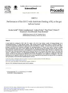
Fig. 1. Temperature profiles of the heat transfer within the BASE case. Moreover, the flow characteristic (inlet pressure as a function of the steam flow) of the steam turbine is determined according to Stodola`s law [30]. In case of wet steam within the steam turbines, the isentropic efficiency is corrected by the Baumann factor. The major assumptions are listed in Table 2. In both cases, the fuel is 50 kg/s bituminous coal (Illinois #6) with a composition (weight-%, as-received) of 64.61 % C, 4.39 % H, 1.39 % N, 0.86 % S, 7.05 % O 12.2 % ash and 9.5 % moisture. The corresponding higher heating value HHVar is 27.07 MJ/kg while the lower heating value is LHVar 25.97 MJ/kg. Steady-state operation has been assumed in both cases. An SNG processing concept including drying and compression for pipeline transportation is not considered in this study. The steam cycle has also been modelled in Aspen using the IAPWS-95 steam tables to check the consistency within both programs. The deviations are negligible.
3. System design Two different cases are considered in this study. The BASE case refers to a combined cycle process for generating only electricity including carbon capture, while in the second case (SNG case), the entire syngas is converted to SNG.
3.1. BASE case The overall system design of the enhanced IGCC with an integrated methanation unit producing SNG is presented in Fig. 2 and simulation results of selected flows are presented in Table 3. The key subsystems of this concept are a gasifier, an air separation unit (ASU), an acid gas removal (AGR) unit, a gas turbine system and a steam cycle. A General Electric Energy (GEE) oxygenblown entrained-flow slagging gasifier with a radiant syngas cooler is used to produce syngas at a temperature of 1250°C and a pressure of 36 bar. The gasifier uses a single-stage, slurry feed design without the need of a coal-drying unit. The slurry feedstock contains 56 weight-% coal, which is crushed before it is mixed with recycled water. The syngas temperature is then reduced to 667°C by producing HP steam through the radiant cooler. Within the gasifier, a heat loss of 0.5 % of coal HHVar is taken into account. The carbon conversion efficiency is assumed to be 98 %. Oxygen with a 98 % of purity is provided by the ASU. The syngas is further cooled to 177°C by a water quench which also separates fly ash through scrubbing. The major part of the separated liquid phase is then recycled to the slurry tank. Following to this cooling section, the syngas enters the water gas shift (WGS) unit (sour shift).
Fig. 2. Flow diagram of the overall concept including the BASE and SNG case.
Table 3: Simulation results of selected flows. Flow no. 1 2 3 4 5 6 7 8 9 10 11 12 13 14 15 16 17 19
Type coal water air nitrogen oxygen raw gas shift gas CO2 (BASE case) CO2 (SNG case) acid gas (BASE case) acid gas (SNG case) syngas SNG syngas air air combustion gas exhaust gas offgas (BASE case) steam (SNG case) steam (BASE case) steam (SNG case)
Temperature [°C] 15.0 177.3 15.0 126.6 93.6 677.0 243.9 45.0 45.0 24.9 28.9 19.8 35 130.9 15.0 426.1 1253.0 588.6 133.2 450.4 582.4 306.6
Pressure [bar] 1.013 35.7 1.013 26 38.0 35.6 34.4 110.0 110.0 1.3 1.3 34 26.9 34 1.0 19.5 19.5 1.1 1.02 129.8 85.0 41.6
Mass flow [kg/s] 50.0 22.0 164.1 124.1 40.0 87.8 165.2 108.0 70.1 1.3 1.3 32.3 32.3 16.7 539.9 539.9 680.8 680.8 680.8 62.7 143.8 104.4
In the BASE case, the syngas first enters a high-temperature shift reactor (HT-WGS) at 225°C and then passes a low-temperature shift reactor (LT-WGS) at 204°C. Based on this two-stage design, the CO concentration is significantly reduced. Subsequently, mercury is removed and the shifted syngas enters the AGR unit. H2S and CO2 are captured by the Selexol process. The captured H2S exits the regeneration column of the first capture cycle by using LP steam and is then sent to a Claus plant. Within the Claus plant a part of the H2S is oxidized to SO2 and finally condensed to elemental sulfur. The CO2 exits the second capture cycle through three flash stages to a multi-stage intercooled compressor to meet the transport conditions of 110 bar and 45°C. The cleaned syngas exits the AGR unit at 20°C and 34 bar and yields 96.6 mole-% H2. Since this is a considerable amount of H2, a dilution with water is used to decrease the firing temperature of the downstream gas turbine system. Additionally, some nitrogen from the ASU is injected into the combustion chamber. The parameters of the gas turbine presented in Table 2 were identified based on the gas turbine SGT54000F manufactured by Siemens [31]. Finally, the steam cycle was designed to maximize the produced electricity through the steam turbine. Figure 1 presents the resulting temperature profiles of the heat transfer within the heat recovery steam generator (HRSG) and external sources. The final offgas temperature of the HRSG is quite high, because a lot of low-temperature heat has to be integrated into the steam cycle particularly in the LT-WGS reactor.
3.2. SNG case The gasification island and the ASU are working under the same conditions as in the BASE case. In contrast to the BASE case, the WGS unit consists of only one shift reactor in conjunction with a bypass of the second stage to provide an adequate H2/CO-ratio for the SNG-synthesis. The conditioned syngas has a mole composition of 32 % H2, 11 % CO, 19.5 % CO2 and 36 % H2O resulting in a feed gas module of M = 3.03 (see section 1). A smaller stream has to be removed in the AGR unit for CO2 transport since the CO shift conversion decreases compared to the BASE case.
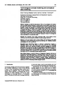
Fig. 3. Flow diagram for the simulated TREMPTM process (SH – superheater, EVA – evaporator, ECO –economizer, HP – high pressure, IP – intermediate pressure, LP – low pressure). Recommendations on the quality and the composition of a syngas fed to the catalytic methanation unit are presented by Gärtner et al. [4] and Seglin and Gould [6]. Subsequently, the prepared syngas enters the TREMP unit. Figure 3 shows the flow diagram of the reactor system. First, the syngas is preheated in a heat recovery system to reach the catalysis activation temperature after recycled gas is mixed into the main stream. The heat is supplied by cooling the product gas of reactor R1 and it is transported via two internal closed loops. The residual heat from reactor R1 is used to produce HP and IP steam. The major part of the gas, about 70 weight-%, is recycled to reactor R1. To overcome pressure losses in the recycle, the gas is compressed to a pressure of 34 bar. The CH4 concentration of the remaining gas increases in the following reactor stages according to the exothermal reaction mechanism presented in Table 1. By cooling the product gas of the second reactor, LP steam gets reheated to avoid erosion in the low-pressure steam turbine caused by water droplets. Moreover, part of this thermal energy is internally shifted to preheat the recycled gas after compression while another part is cooled by the cooling tower. The product gas of reactor R4 is first cooled by superheating LP steam and then preheating IP and LP steam before the remaining heat is transferred to the cooling tower. Further information regarding the heat integration is given by the temperature profiles in Fig. 4. The equilibrium diagram in Fig. 5 shows the relationship between the temperature and the CH4 concentration on a dry basis for the TREMP unit. The black solid line represents the states of complete chemical equilibrium while the horizontal dashed line in Fig. 5 is the upper temperature limit for the operation of the catalyst (sintering temperature). Every reactor has a significant contribution to the overall CH4 conversion, ranging from 8 to 21 percentage points. In comparison to the reactors R1 to R3, the conversion rate of reactor R4 is low. At the outlet of the reactor R3 no CO is left and only methanation over CO2 takes place. However, the contribution of reactor R4 is important for improving the SNG quality. Recycling the product gas around reactor R1 (point 4) has two advantages. The initial CH4 concentration increases from point 1 to 2B and the adiabatic equilibrium temperature is well below the sintering temperature of the catalyst (around 750°C). In case of no gas recycle, the adiabatic equilibrium temperature of reactor R1 would be above the sintering temperature (Point 2A). In respect to the conversion, an advantageous temperature between 450°C–750°C is achieved.
Fig. 4. Temperature profiles of the heat transfer within the SNG case. 1050
2A
Temperature [°C]
900 750
3 5
600
R1 R2
450
7 R3
300
R4
2B gas recycle
150
1
4
6
8
treated gas 10 10%
20 20%
SNG 10
0
0 0%
9
30 30%
40 40%
50 50%
60 60%
70 70%
80 80%
90 90%
100 100%
CH4,dry fraction [mole-%]
Fig. 5. Equilibrium curve of the four-stage TREMP at 27 bar. When approaching a temperature below 240°C, the reaction breaks down. The SNG product consists of 47 mole-% CH4, 47 mole-% H2O, some N2 and a trace of H2. Condensing the water in a downstream gas processing unit would result in a CH4 mole fraction of 88 % (see Fig. 5). The LHV of the SNG is 43.2 MJ/kg while the HHV is 48.0 MJ/kg. A mass flow of 16.5 kg/s SNG is provided by the TREMP unit as feed-in gas to the grid.
4. Results and discussion The performance of both cases is presented in Fig. 4. The gas turbine system and the steam turbine produce electricity that is partly consumed by various internal subsystems. The steam cycle consists of steam turbines and pumps at three pressure levels (HP, IP and LP). Regarding the ASU, the consumption considers mainly the air compressor. The gasifier includes the compression of oxygen, some pumps as well as the work required for coal milling. In the AGR unit various pumps, the refrigerant compressor and a recycle compressor are taken into account. Moreover, an electricallydriven multi-stage compressor is used to provide the pressure for CO2 transportation. Despite its small share in internal consumption, the recycle compressor of the TREMP is presented as a separate block. Auxiliaries include components such as coal and slag handling, ASU and AGR auxiliaries, cooling tower fans and auxiliaries used for the gas turbine system and the turbomachinery within the steam cycle.
relative input of coal [% of LHV]
70 61.4 % 60
50
54.8 % 46.2 %
40 37.6 %
(+) steam cycle (+) gas turbine (+) SNG (-) recycle TREMP (-) auxiliaries (-) gasification island (-) ASU (-) AGR (-) CO2 compression (+) net output
30
20 BASE case
SNG case
Fig. 6. Cycle efficiency and power distribution of the analyzed cases. Table 4. Characteristic data of the steam cycle for both cases. live steam pressure HP live steam pressure IP live steam pressure LP live steam temperature HP live steam temperature IP live steam temperature LP mass flow heat input heat output generated electricity
Unit bar bar bar °C °C °C kg/s MW MW MW
BASE case 168.0 85.0 7.7 597.4 582.4 119.1 246.1 549.9 -203.4 192.7
SNG case 129.8 41.6 5.9 450.4 306.6 317.4 187.1 297.1 -166.1 90.2
The key parameters of the steam cycle subsystem are presented in Table 4. The overall net efficiency for the BASE case is 37.6 % while it is 54.8 % for the SNG case based on the LHV of coal. The corresponding efficiencies based on the HHV of coal are 36.1% and 52.6 %, respectively. The gas turbine accounts for 69 % of the gross output in the BASE case. Accordingly, 31 % of the gross output is generated by the steam cycle. 20 % of the gross electricity output is consumed internally, mainly by the ASU, the AGR and the CO2 compressor system. As presented by Buttler et al. [7], the reactors must stay at the activation temperature range during standstill to reduce the start-up time. In this study, the heat that needs to be provided is not considered in the BASE case. The overall SNG product amounts to 16.5 kg/s corresponding to 712 MW based on the LHV. The gross power of the SNG case is larger compared to the BASE case, but consists of two different products. Electricity generated by the steam turbine amounts to only 11 % of the gross power. Haldor Topsøe presented a heat recovery of about 20 % for the TREMP unit based on the heating value of the syngas [12]. In this study, a heat recovery of 25 % is obtained based on LHV corresponding to 22 % based on HHV. The gas turbine does not operate in the SNG case since the entire syngas is converted to SNG in the methanation unit. Consequently, no water needs to be provided for the saturation of the syngas, resulting in a decreasing of the heat output of the steam cycle in the SNG case (see Fig. 4). To cover the internal consumption, additional electricity has to be purchased from the grid. The efficiencies of the SNG case do not include the import of electricity. The internal consumption slightly decreases for the SNG case. On one hand, additional work for compression is required by the gas recycle of the TREMP, while on the other
hand, less work is required for the CO2 compression caused by a decreasing CO2 concentration of the syngas entering the TREMP unit. In both cases, the share of internal consumption of the CO2 compressor, the ASU and the AGR unit amounts to more than 90 %. Hence, the electrical consumption of the gasification island, the auxiliaries and the TREMP recycle compressor are of minor importance. Although the reaction within the TREMP unit is exothermal, the released heat cannot fully substitute the heat that is supplied by the HRSG in the BASE case. A full integration of the heat released by the reactors of the TREMP unit is not possible due to an excess low-temperature heat supply. In particular, the low-temperature heat from reactors R3 and R4 cannot be integrated into the steam cycle due to a similar temperature profile of the WGS. Hence, only 83 % of the available heat from the TREMP unit can be integrated. Compared to the BASE case, 51 % of the heat transferred in the HRSG can be substituted in the SNG case. Therefore the total mass flow of steam decreases in the SNG case. Based on the released heat from the methanation unit, 28 % are recovered as HP steam, 41 % as IP steam, 22 % as LP steam and 9 % is used for internal heat recovery. In both cases, IP steam needs to be provided to the water quench, scrubber and the WGS unit. In accordance to the Stodola law, the HP and IP live steam parameters decrease since the supplied heat decreases disproportionately, because it is related to the total mass flow. However, the live steam temperature of the LP steam turbine increases. In the off-design case the isentropic efficiencies for the IP and LP steam turbine are reduced to 95.3% and 89.2%, respectively. As a result the electrical power generated by the steam turbine decreases significantly. In comparison to the conventional IGCC design, the overall net efficiency of the coal-to-SNG process is significantly higher. A straight thermodynamic comparison of the two analyzed cases is not feasible due to the production of different products. The overall net efficiency decreases by 1-2 %-points when including the import of electricity from the grid as well as an SNG gas processing unit using a multi-stage compressor for transportation at 80 bar. Chandel and Williams [32] present overall net efficiencies ranging from 44.6 % to 49.4 % (based on HHV) using lignite in different types of gasifier for the co-production including carbon capture. Li et al. [17,18,[19]] found an overall efficiency of 59 % to 65 % (based on LHV) for their proposed cogeneration system by using some part of the SNG from the TREMP in a combined cycle. The study of Karellas et al. [20] showed an overall efficiency of 66.5 % to 69 % (based on LHV) when the heat of the methanation unit was used for electricity generation in a steam cycle. In contrast to this study, no import of electricity is required.
5. Concluding remarks This study presents an energetic analysis for an IGCC concept with carbon capture producing SNG and electricity based on two characteristic cases. The overall net efficiency for the BASE case producing only electricity is 37.4 % while it is 54.8 % for the SNG case (based on the LHV). In the SNG case, additional 1.9 % electricity related to the coal input based on the LHV has to be purchased from the grid to cover the internal consumption. The released heat of the methanation unit is not sufficient to produce enough steam for generating electricity. Additionally, the low-temperature heat cannot be fully integrated into the steam cycle. The waste heat from the TREMP unit is mainly recovered by producing HP and IP steam. Further investigations could be conducted for the heat integration scheme, e.g. by using a mixed integer non-linear optimization algorithm. In the next step, an exergy, economic and exergoeconomic analysis [33] will be performed to improve the understanding of the overall process. As a long-term task, other units (e.g., a methanol production unit) can be integrated into the IGCC concept to increase the product diversity.
Nomenclature AGR ar ASU ECO EVA GPU HHV HP HRSG IGCC IP LHV LP SNG SH TREMP WGS ΔHr
acid gas removal as received air separation unit economizer evaporator gas processing unit higher heating value high pressure heat recovery steam generator integrated gasification combined cycle intermediate pressure lower heating value low pressure synthetic/ substitute natural gas superheater Topsøes recycle energy efficient methanation process water gas shift enthalpy of reaction
References [1] [2] [3]
BP Statistical Review of World Energy; 2012. U.S. Energy Information Administration, International Energy Outlook; 2013. Sudiro M., Bertucco A., Synthetic natural gas (SNG) from coal and biomass: a Survey of Existing Process Technologies, Open Issues and Perspectives. In: Primoz Potocnik, editor. Natural Gas. Sciyo Publisher, 2010. chaper 5Pardemann R., Kohlekraftwerke mit Vergasung Stand der Technik und Entwicklungspotentiale (german). Technische Universität Bergakademie Freiberg, Faculty of Mechanical, Process and Energy Engineering, Institute for Process and Energy Engineering and Chemical Engineering; 2010. [4] Gärtner C, Gutte H, Franke P, Bauersfeld S, Scheithauer D, Meyer B, Pardemann R, Boblenz R. Forschungsvorhaben Untersuchung zur energetisch und wirtschaftlich optimierten Kohleverstromung durch Polygeneration, Schlussbericht - Teile I und II: Kurzdarstellung und eingehende Darstellung (german). Technische Universität Bergakademie Freiberg, Faculty of Mechanical, Process and Energy Engineering, Institute for Process and Energy Engineering and Chemical Engineering, Federal Ministry for Economic Affairs and Energy; 2011. [5] Kopyscinski J, Schildhauer TJ, Biollaz S. Production of synthetic natural gas (SNG) from coal and dry biomass – a technology review from 1950 to 2009. Fuel 2010;89(8):1763-1783. [6] Seglin L, Gould RF. Methanation of Synthesis Gas. Atlantic City, USA: American Chemical Society; 1974. [7] Buttler A, Kunze C, Spliethoff H. IGCC-EPI: Decentralized concept of a highly load-flexible IGCC power plant for excess power integration. Applied Energy 2013;104: 869-879. [8] Rönsch S, Ortwein A. Methanisierung von Synthesegasen – Grundlagen und Verfahrensentwicklungen (german). Chemie Ingenieur Technik 2011;83(8):1200-1208. [9] Ogriseck K. Untersuchung von IGCC-Kraftwerkskonzepten mit Polygeneration und CO2Abtrennung (german). Freiberg, Germany: Technical report VDI Reihe 6 Nr.544, VDI publishing house; 2006. [10] Jensen J, Poulsen J, Andersen N. From coal to clean energy. Nitrogen+Syngas 2011;310.
[11] Götz M, Heinrich T, Graf F, Bajohr S, Baundry A. Methanisierung – Technische Ansätze und deren Bewertung; International Biomass Conference; 2010 May; Leipzig, Germany. [12] From solid fuels to substitute natural gas (SNG) using TREMP TM. Lyngby, Denmark: Haldor Topsøe; 2009. [13] Li S, Jin H, Zhang X. Exergy analysis and the energy saving mechanism for coal to synthetic/substitute natural gas and power co generation without and with CO2-capture. Applied Energy 130 (2014) 552-561. [14] Li S, Ji X, Zhang X, Gao L, Jin H. Coal to SNG: Technical progress, modeling and system optimization through exergy analysis. Applied Energy 136 (2014)98-109. [15] Gassner M, and Maréchal F.Thermo-economic process model for thermochemical production of Synthetic Natural Gas (SNG) from lignocellulosic biomass. Biomass And Bioenergy 33 (2009), pp. 1587-1604. [16] Koytsoumpa E-I, Atsonios K, Panopoulos KD, Karellas S, Kakaras E, Karl J. Modelling and assessment of acid gas removal processes in coal-derived SNG production. Applied thermal Engineering 74 (2015), pp. 128-135. [17] Li S, Jin H, Lin G, Zhang X, Ji X. Techno-economic performance and cost reduction potential for the substitute/synthetic natural gas and power cogeneration plant with CO2-capture. Energy Conversion and Management 85 (2014)875-885. [18] Li S, Jin H, Lin G. Coal based cogeneration system for synthetic/substitute natural gas and power with CO2 capture after methanation: Coupling between chemical and power production. Journal of Engineering for Gas Turbines and Power, Vol.136; 2014 September. [19] Li S, Jin H, Lin G. Cogeneration of substitute natural gas and power from coal by moderate recycle of the chemical unconverted gas. Energy, Vol.55; 2013 June. [20] Karellas S, Panopoulos KD, Panousis G, Rigas A, Karl J, Kakaras E. An evaluation of Substitute natural gas production from different coal gasification processes based on modeling. Energy 45 (2012)183- 194. [21] Bu XP, Wang P, Xin SH, Liang DM, Gi XG. Analysis of coal gasification/polygeneration to produce substitute natural gas (SNG). Coal Chem Ind 2007;6:4-7 [22] Aspen Plus®, http://www.aspentech.com. [23] Ebsilon, https://www.steag-systemtechnologies.com/ebsilon_professional.html. [24] Black J. Cost and Performance Baseline for Fossil Energy Plants Volume 1: Bituminous Coal and Natural Gas to Electricity. National Energy Technology Laboratory. DOE/NETL2010/1397; 2010. [25] Ullmann F. Ullmann`s Encyclopedia of Industrial Chemistry Wiley-VCH. Weinheim, Germany; 1998. [26] Doctor RD, Molburg JC, Thimmapuram PR. KRW Oxygen-Blown Gasification Combined Cycle: Carbon Dioxide Recovery, Transport, and Disposal. Energy Systems Division, Argonne National Laboratory; 1996. [27] Ludwig E. Applied Process Design III. Gulf Professional Publishing; 2001. [28] Schoofs GR. Sulfur Condensation in Claus Catalyst. Hydrocarbon Processings; 1985. [29] Deckers M. CFX aids design of world´s most efficient steam turbine. Germany; 2003. [30] Stodola A. Dampf- und Gasturbinen (german). Berlin, Julius Springer; 1924. [31] Siemens gas turbines, http://www.energy.siemens.com/hq/en/fossil-power-generation/gasturbines/sgt5-4000f.html. [32] Chandel M, Williams E. Synthetic Natural Gas (SNG): Technology, Environmental Implications, and Economics. Duke University; 2009. [33] Bejan A, Tsatsaronis G, Moran M. Thermal Design and Optimization. John Wiley & Sons, Inc.; 1996.