in direct AC-AC converter application. Main focus will be the. Single-Phase Matrix Converter (SPMC), DC Chopper operational dc chopper functions in the first ...
IEEE PEDS 2005
Modelling and Simulation of a DC Chopper Using Single Phase Matrix Converter Topology Siti Zaliha Mohammad Noor Faculty of Electrical Engineering Universiti Teknologi Mara 40450 Shah Alam,Malaysia ctzaliha.mn @ yahoo.com
Abstract - Choppers are widely used for traction motor control in electric automobiles and other electric transportation system. In those applications, control of dc motor's speed is required where the supply is dc or an ac voltage that has been rectified. This paper presents work on development of four quadrant DC chopper based on the SPMC topology, an advanced topology that hypothetically could perform many different converter functions.
Prior to hardware implementation a computer simulation model was developed using the Power System Block Set (PSB) within the MATLAB/Simulink (MLS) environment, to study the behaviour of the proposed converter. Successful results presented are mainly due to the use of resistive load to reduce complexities. Results from PSB simulation are compared with those obtained from PSpice to ascertain its validity. The output is being synthesized using Pulse Width Modulation (PWM) technique. It is shown that the same SPMC topology could be used as a DC chopper extending the versatility of the topology a desirable feature in the future as increases in costs for skilled manpower could be tradedoff with versatile technology.
Power System Block Set (PSB), Pulse Width Modulation (PWM), Single-Phase Matrix Converter (SPMC), DC Chopper
I.
Ahmad Farid Abidin Faculty of Electrical Engineering Universiti Teknologi Mara
Mustafar Kamal Hamzah
Faculty of Electrical Engineering Universiti Teknologi Mara 40450 Shah Alam, Malaysia mustafar@ salam.uitm.edu.my
INTRODUCTION
40450 Shah Alam, Malaysia
by Hossieni [8], Abdollah Khoei [9] and Saiful [10]. To date, the authors have only found those four published works on SPMC but none has proposed the use of the SPMC topology
SPMC chone
appos. inDC chopperapplications. Al
lSb
Sa
Cr i
I&
I
S3b
S2b
S2a L
s4a
I
S4b
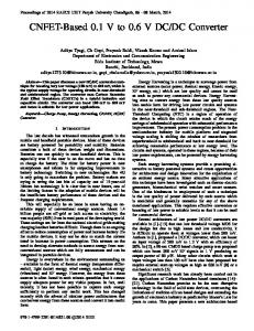
Figure 1: AC-AC single-phase matrix converter topology
In this work, DC chopper also known as dc-to-dc converters were presented to operate as a variable dc voltage from a fix dc voltage using SPMC topology that has been used
in direct AC-AC converter application. Main focus will be the operational dc chopper functions in the first and third
quadrant, nevertheless the operation of the second and fourth quadrant are also described. To ascertain its feasibility
simulation models were developed using MATLAB/Simulink and PSpice to study the behaviour of the proposed technique. Successful results presented are mainly due to the use of resistive load without the introduction of inductances to reduce complexities. The DC Chopper is based on fourquadrant operation with the output being synthesized using Pulse Width Modulation (PWM) technique. The result of this work has indicated that the same SPMC topology [7, 9, 10] The Matrix Converter (MC) is an advanced circuit topology that offers many advantages such as the ability to maybe used as a DC chopper. This versatility is a desirable in the future as increases in costs for skilled manpower enrgbcktothuilt,insodfeature utility, sinusoidal Input and regenerate energy back to theregenerate maybe overcame by having a versatile technology. output current and controllable input current displacement factor [2]. MC has the potential of affording an "all silicon" Results of loads with inductance are also included with a solution for AC-AC conversion, removing the need for brief description of problems encountered in the absence of reactive energy storage components used in conventional suitable commutation strategies that results with voltage rectifier-inverter based system. Its topology was first proposed spikes that needs to be avoided. The commutation strategy by Gyugyi [3] in 1976. Obviously all published studies dealt used in this work has to a certain extent reduced the spikes with mainly the three-phase circuit topologies [4-6]. that has been resulted but still requires further investigations in to solve the problems, a common phenomenon in an efor effort tosletepolm,acmoXhnmnni ZXI was an matrix converter denoted as SPMC The Single-phase *'arorveanalQ matrix converter topologies. first realised by Zuckerberger [7]. Other works includes those Choppers are widely used for traction motor control in electric automobiles and other electric transportation system. In those applications, control of dc motor's speed is required where the supply is dc or an ac voltage that has been rectified. Other applications of dc chopper also include high-current DC applications in industries [1] which have many operational benefits over conventional diode or thyristor rectifiers.
in
0-7803-9296-5105/$20.00 ©2005 IEEE
827
II.
SINGLE PHASE MATRIX CONVERTER
The SPMC requires 4 bi-directional switches as showni in Figl; each capable of conducting current in both directions, blocking forward and reverse voltages [10] Using carefully designed switching sequences the following step-up and stepdown frequency AC-AC conversion could be realised [11, 12] as shown in fig. 2. It requires the use of bidirectional switches capable of blocking voltage and conducting current in both directions. Unfortunately there is no discrete semiconductor device currently that could fulfil the needs [13, 14] and hence the use of common emitter anti-parallel IGBT, diode pair as shown in Fig. 3. The IGBT were used due to its popularity amongst researchers that could lead to high-power applications with reasonably fast switching frequency for fine
reference [15, 16]. The polarity of the output voltage and the direction of the energy flow cannot be change. By referring to the combination shown in fig Sb, if the load is a separately excited motor of constant field, then the positive voltage and positive current in the first quadrant, give rise to a "forward drive". Changing the polarity of both the armature voltage and the armature current result in a "reverse" drive (quadrant III) while in quadrants II and IV, the direction of energy flow is reversed and the motor operates as a generator braking rather
than driving.
dd Vd Forward Forward Reverso de Braking I -"SI IV
control.
Reverse Drive
Z
V
-+ve
VL -ve
1L-ve
III
V+ve Id
V
-ye
L, +ve
IV
Figure 5b: The polarities DC CHOPPER BASED ON SPMC
Figure 5a: Four quadrant operation -
A tDb Slal
2
-
~~~~~~~~(b)
mia0r2b .' Slal Dlb
Ed,~ ~ D3b
-
D4b
Figure 3 :Conventional dc chopper
Slb S2b S2B Sib S2b R L t1 > X t Ed'k L m T 17S3a D3b S4a m S4b { 4 4 P . Sla
Figure 4: DC chopper using SPMC
CONVENTIONAL DC CHOPPER III. A dc chopper converts directly from dc to dc also known as a dc to dc converter. It is conlsidered a dc equivalent of an AC transformer with a continuously variable turn's ratio. It can be used to step down or step up a dc voltage source [15]. Apart from those applications it can also be used in regenerative braking of dc motors, dc voltage regulators and also used in conjunction with an inductor, to generate a dc current source, especially for current source inverter applications [16]. A conventional dc chopper is as illustrated
anud
in fig. The input voltage of matrix converter operated at Figure 3 is: (1) EdC=R.i+L-+E dt for passive R, L and E load. [8] DC choppers may be classified according to the number of quadrants of the Vd-Id diagram as shown in fig.5a and the polarities as in fig. Sb in which they are capable of operating. Detailed treatment of the theory could be obtained from
IV.
Proposed DC chopper is as shown in fig.4. It has similar structure with those of the SPMC as shown in fig. 1, the difference being the input dc voltage. Practical realization of matrix converters requires the use of four-quadrant switch of bi-directional with In capable of fig.3 [10]. it has comparison 4 bi-directional conventional dc chopperoperation switches as opposed to the use of 4 switch and 4 diodes in conventional dc within chopper.eachThis arrangement chosen of it allows because switch independentwascontrol the current in both direction. This back-to-back bi-directional arrangement of the matrix convertef also has lower conduction losses than a diode bridge switch arrangement during commutation of the load current [14]. In this circuit configuration, the IGBTs were used because of its high switching frequency and high current handling capabilities. Diodes arranged in series to provide the reverse voltage blocking capability [17]. A. Pulse-Width Modulation (PWM) The output of the dc chopper maybe controlled using the (PWM), generated by comparing a triangle wave signal with an adjustable dc reference and hence the duty cycle of the switching pulse could be varied. This algorithm is required to provide a stream of PWM train to turn on and off the switches that will synthesize the required dc to dc conversion. This is as illustrated in fig.4.
828
Vg
Trangularwavesignal Rebrece sgnal
/c8r~ers~na~ 4
(a/ustab1e)
7B T
CuFbnw
Outut PWM pulsetrin . Figure 6: PWM waveform
DODE
ei
Cuntw DIODE
IGBT
in the diagram represents the safe commutation switch during each particular state that is continuously turned-on as in Table 1. The dark arrow on the switch indicates that the switch is turned-on and behaves as the power switches performing the required converter operation.
1) First Quadrant (QJ)
[1 - r r r f E r r | rThe load current are current flows from the _ i | ! _ T Figure 7: Bi-directional switch
B. Commutation Problem The use of Pulse Width Modulation as in fig.6 as the switching algorithm in this- converter,' results with possible reversal current if inductive loads are used, during switch turnoff. Detailed treatment on safe-commutation problem can be obtained in reference [18] restated here briefly for completeness. Theoretically the switching sequence in the SPMC must be instantaneous and simultaneous; unfortunately impossible for practical realization due to the turn-off IGBT characteristic, where the tailing-off of the collector current will create a short circuit with the next switch turn-on. This problem occurs
when inductive loads are used. A change in current due to PWM switching will result in current and voltage spikes being generated resulting in the occurrence of a dual situation. First current spikes will be generated in the short-circuit path and secondly voltage spikes will be induced as a result of change in current direction across the inductance. Both will destroy the switches in use due to stress. A systematic switching sequence is required that allows for the energy flowing in the IGBT's to decay in a free-wheel manner.
In conventional dc chopper, the free-wheeling diode is used to this purpose. In SPMC this does not exist, hence a switching sequence needs to be developed to allow forced on controlled free-wheeling. This is to protect the converter from being damaged as a result of voltage and current spikes as described. In conventional converter this is normally implemented in the form of free-wheeling diodes in inverter systems arranged in anti-parallel with power switching devices. In this study, we will focus our attention to switching spikes and assume that there is no-change in the direction of current so as to minimise the complexities.
C. Switching Strategies The implementation of the SPMC as a dc chopper requires different bi-directional switching arrangements depending on the desired operational requirements of the four quadrants defined. The magnitude of the output voltage of the converter is controlled by PWM variations in duty cycle. The switching sequences are designed to follow Table 1. Figs.8 to 11 illustrates the four quadrant operation of dc chopper using SPMC topology. The dotted line flow of current
positive as shown in fig. 8. The load supply to the load. To achieve this
tured-on and act as a power switch performing the required converter operation
condition, SI a and S4a are
synthesizing the output dependent on the control algorithm being developed. During turn-off of Sla, switches S3b and Saaemitie scniuul Ndrn hscce 4 co unction ction andactstsin con returN and theloopz l f cunti to c pe the current return for ~~~~~~~~~~to comptlete w S turned OFF.
2) Second Quadrant (Q2) The load voltage is positive with negative load current as shown in fig 9. The loads current flows out of the load. To achieve this condition, Switch S3a and S4b will operate while Slb will be continuously turned-on, the voltage E will drives current through the load and when both switch S3a and S4b are turn off, load dissipates energy through S lb to the supply. TABLE 1: Switching pattern for four-quadrant dc-to-dc matrix converter Switches
Quadrant_
Quadrant
Sla
Modulate
Sib
S2a
Off Off
Continuously On Off
S2b
Off
Off
Off
S3a
Off S3bS3b ~Continuously On Continuously S4a On
54b Sib
zSb
Off
Continuously
Off
On
Switching
Continuously On
Off
Off
Off Continuously On
Off
Off
Switching
On
On
Off
S2b
S2a E
t 5 K
islb
1R AiS3a\
Off
Off Modulate
Continuously Continuously
Off
Sia
Quadrant Off
|Quadrant Off
S2a E
R S4ai
\ S4b L
Figure 8: First Quadrant
S3af\FS3b
SL
L S
Sa \
2S4b
S
Figure 9: Second quadrant
3) Third Quadrant (Q3) The load voltage and load current are negative as shown in fig. 10. It is the reverse of first quadrant, where the load current flows from the supply to the load through a different route. To
829
achieve this condition, S2a and S3a are turned-on and act as a power switch performing the required converter operation synthesizing the output dependent on the control algorithm being developed. During turn-off of S2a, switches S3a and S4b are maintained as continuously ON during this cycle; S3a to complete the loop for current return and acts in conjunction with S4b to provide free-wheel operation whenever S2a is turned OFF.
practical results are presented to verify some of the results. Parameters used are as shown in table 2. | RrVER lll Cnn Con ! RE + _Ar--nA T
T7 Sia
Sib
Sa
Sia
S2874 S2b
W?~ ~~ ~~~~~~~~~~~~~~~~~~~~~~~~~~~ C R~~~~~~~~~~~~ DC
C
Sib
S . 23
S4. Sdb L
Figure 10: Third Quadrant
n4' DC~~~
I.
SS3a
A
b
a..Conn2
DC
S4a
Source
l
_ Il _ Cnn Conn2
-
~~~~~~~~~~~~~~~DRrVERI 1n2
E I L...,..J EL.rJ~~~~~~~~~~~~~~
1
Connl
*n2
Connl
Conn2
Subsystemti
I~~~~~~~~~~~~~~.VVV~~~~~~~~~~~~~~rW1 ~~~~~~~~~~Subsystemt
S4b
Figure 12: Top level main model of SPMC in MLS LCConn
Figure 11: Fourth Quadrant
e
E
L
iGBT I
Terminator
DIode2
Term
4) Fourth quadrant (Q4) In the fourth quadrant, the load voltage is negative but the load current is positive as shown in fig. 10. The loads current flows out of the load. To achieve this condition, Switch S3a and S4b will operate while Slb will be continuously turnedon, the voltage E will drives current through the load and when both switch S3a and S4b are turn off, load dissipates energy through Slb to the supply. V.
oioeI
1T
F C an
l
O O
posite ov1
Reptin
Se*q uencel
Figure 14: PWM model circuit in PSB
In this simulation implementation, Power System Block Set (PSB) in MLS and PSpice are used to model and simulate the circuit. The DC Chopper was supplied by 30V DC voltage source; the load takes the form of a pure resistive 50 Q2 with battery E representing a back emf of a dc motor. Fig. 12 and 13 show the MLS model circuit used to implement the simulation, whilst fig. 15 is the Pspice implemented circuit model for comparison. The PWM model is as shown in fig. 14. A constant representing a straight line or reference signal is compared with the triangular wave as a carrier signal to produce the required respective PWM output. In PSB, the comparison of these two different signals is done by using the "Relational Operator" Block. The "constant2" block represents the maximum magnitude of the pulse generated the "Repeating Sequence" Block act as triangular wave and "constant2" i represents the modulation index of the PWM.
4-
4Cj3 52 4' N386 T ~ 81(856F2L t7!-8-4000 *.* LJF00 BUKOO 5,.\,. cIt
851(0554u 3
0
0(1(3 b5 I
5o--
80085
-ua
o4 7 SIN 3 T;
, duo
50
1 D31X,00 'U8.7 4b Ef- 44-t .3 Z5; 44b 0G738001 _______ 8(5-0( d
i-
i! xTABLE 1': j1ev3 0!03 Figure
RESULTS
Simulation results are presented in this section arranged in accordance to the followings; neglecting inductance, with no commutation during switch turned-off and with safe commutation switching arrangements. Simulations are carried out with MATLAB and Pspice to study the behaviour. Some
conal sit
C
SIMULATION IMPLEMENTATION
VI.
IGBT2
15: Model circuit in
PSpice
TABLE 2: Parameter for simulation model in MATLAB and Pspice 30 V,,, Input Source (DC) Sample Modulation Index (mi) 0.75 R =50 Q) Resistance L = 0.004H Inductance
830
A. Neglecting Inductance
B. RL Load (with no-commutation)
To simplify inductance is neglected with results in fig. 16 to 23. All the results are as expected in theory.
Inductance is introduced to represent windings in machines. Without commutation results are as in fig.24 to 25, with spikes generated tabulated in Table 3. Severe voltage are noticeable. For an input of 30V, the voltage spikespikes is in the region of +176 to -196, a cause for concern.
VoltV,o r>;
*v!
W
Curr nt
"Eurrent
Figure 16: Output voltage and current for Ql operation with PSB.
Voltage-
Voltage
-Current
Figure 23: Output voltage and current for Q4 with PSpice. Current
Figure 17: Output voltage and current waveform for Ql with PSpice. Current Voltage
.
goK
.
f[
Figure 24: Output voltage and current for Q I PSB without commutation Figure 18: Output voltage and current waveform for Q2 with PSB.
Voltage
Current
Current Figure 25: Output voltage and current for Q3 PSB without commutation
C. RL Load (with safe-commutation) Figure 19: Output voltage and current waveforrn for Q2 with PSpice.
Voltage
Safe-commutation results with the
where spikes are reduced.
following figs. 26 & 27,
.qrei,'
Figure 20: Output voltage and current waveform for Q3 with PSB.
*,
.
Ij
*
11
=.
Figure 26: Output voltage and current for Ql PSB with commutation. Voltage
Current
I - - .-
Figure 21: Output voltage and current for Q3 with PSpice.
Figure 27: Output voltage and current for Q3 PSB with commutation, TABLE 3: Simulation result for RL load with no commutation
Voltagq
Current
Operation Quadrant
(V)
Current (A)
27
0.44
Vmax 176
2
3.5
-0.03
16
3 4
-26.2 -3.4
-0.51 0.03
179 5.9
1
Figure 22: Output voltage and current waveform for Q4 with PSB.
831
Voltage
._____ __'_,_.
Voltage Spike (V)
Vmin -196
-5
-140 -15.5
Current
Spike (A) Imax Imnin
0.14 1-0.17
0.01
-0.01
0.23 1 -0.154 0.007 ] -0.012
VII. EXPERIMENTAL RESULT
ACKNOWLEDGMENT
A simple laboratory test-rig was developed to ascertain the validity of some of the results. Fig. 28 to 29 shows measurement from oscilloscope for first and third quadrant respectively. The MC was supplied with 30V DC and loaded with R = 50 Q and back emf, E = 5V and operated at modulation index = 0.75. Inductance was not used to reduce of suitable switching complexities in the absence p . arrangements that could eliminate those spikes as a result of PWM switching sequences. Results presented are in good agreement those simulated.
Financial support from University Technology Mara for carrying out this work is gratefully acknowledged.
A. First quadrant
!.
___________ ;_________
Fig 28a: Output voltage(scale Y: 5V/Div X:5ms/Div)
B. Third Quadrant
REFERENCES [1] [2]
Vince Scaini & Tom MA, "High-current DC choppers in the Metal
Industry", IEEE Industry applications Magazine, April2002, pp 26-
Venturini M., "A New Sine Wave in Sine Wave Out, Conversion
Technique Which Eliminates Reactive Elements," Proceedings
Powercon 7, pp.E3_1-E3_15, 1980.
Gyugyi,L and Pelly,B.R, "Static Power Chargers, Theory, Performance and Application," John Wiley & Son Ic, 1976 [4] Oyama, J., Higuchi, T., Yamada, E., Koga, T., and Lipo, T., "New Control Strategies for Matrix Converter," IEEE Power Electron. Spec. Conf. Rec., 1989, pp. 360-367. T., "Numerical Study of Control Strategies for Frequency Sobczyk, -r [5] Conversion with a Matrix Converter," Proceedings of Conference on Power Electronics and Motion Control, Warsaw, Poland, 1994, pp. 497-502. [6] Cho, J.G., and Cho, G.H, "Soft-switched Matrix Converter for High Frequency direct AC-to-AC Power Conversion," Int. J. Electron., ;1992, 72, (4), pp. 669-680. -J [7] Zuckerberger, A., Weinstock, D., Alexandrovitz A., "Single-phase ;; Matrix Converter," IEE Proc. Electric Power App, Vol.144(4), Jul Fig 28b: Output current(scale Y: 1997 pp. 235-240 200mA/Div X:Sms/Div) Hosseini, S.H.; Babaei, E, "A new generalized direct matrix [8] converter," Industrial Electronics, 2001. Proc. ISLE 2001. Vol(2) 2001 pp1071-1076 Abdollah Koei & Subbaraya Yuvarajan, "Single-Phase AC-AC Converter Using Power Masfet's," IEEE Transaction on Industrial Electronics, Vol. 35, No.3, August 1988 pp442-443 Firdaus, S., Hamzah, M.K.," Modelling and simulation of a singleAw | Si l | [10] phase AC-AC matrix converter using SPWM,", Student Conference on Research and Development 16-17 July 2002, SCOReD2002., : pp286-289. Zahiruddin ldris, Mustafar Kamal Hamzah & Ngah Ramzi Hamzah, [11] Fi 29b Ouput tirint scal Y:"Modelling & Simulation of a new Single-phase to Single-phase Cycloconverter based on Single-phase Matrix Converter Topology 200mAJDiv X:5ms/Div) Pulse Width Modulation Using Sinusoidal with
[3]
D[9
Li Li
tj . (scle Y Fig 9a: utpt votag
5V/Div X:5ms/Div)
VIII.
CONCLUSION
The SPMC topology has been presented capable of being operated as dc chopper to operate in the four quadrants similar to the conventional dc chopper. Simulation models in MATLAB/Simulink and PSpice are used to study the behaviour of the proposed technique and has shown good agreement with those obtained experimentally. The result of this work has indicated that the same SPMC topology [7, 9, 10] maybe used as a DC chopper. This versatility is a desirable feature in the future as increases in costs for skilled manpower maybe overcame by having a versatile technology. The commutation strategy used in this work has to a certain extent reduced the spikes that has been resulted but still requires further investigations in an effort to solve the problems, a common phenomenon in matrix converter topologies. Further investigations are however in order to eliminate the switching transients caused by PWM particularly when applications involved the use of inductances, in an effort to use the SPMC topology as a dc chopper.
MATLAB/Simulink", IEEE Sixth International Conference PEDS
[12]
[13] [14]
[15] [16]
[17] poc[171
[18]
2005, Kuala Lumpur, Malaysia (to be presented) Zahiruddin Idris, Mustafar Kamal Hamzah & Ahmad Maliki Omar
"Implementation of Single-Phase Matrix Converter as a Direct ACAC Converter Synthesized Using Sinusoidal Pulse Width Modulation with Passive Load Condition", IEEE Sixth International Conference PEDS 2005, Kuala Lumpur, Malaysia (to be presented) Wheeler, P.W., Clare, J.C., Empringham, L., Bland, M., Kerris, K.G., "Matrix converters," IEEE Industry Applications Magazine,
Vol. 10 (1), Jan-Feb2004, pp. 59 -65. Wheeler, P.W., Rodriguez, J., Clare, J.C., Empringham, L., Weinstein, A., "Matrix converters: a technology review," IEEE Transactions on Industrial Electronics, Vol. 49 (2), April 2002, pp. 276 - 28 M. D. Singh and K. B. Khanchandani, "Power Electronis", Publisher: Tata McGraw-Hill Publishing Company Limited 1998 Muhammad H.Third Rashid, "Power Electronic Circuit, Devices and Edition 2004 Prentice Hall.
Application",
Dr. Patrick W. Wheeler, "The Matrix Converter-future possibilities",
LEE Colloquium Update on New Power Electronic Techniques, 23 May 1997 Page(s): 1/1 - 1/5 Kwon, B.-H.; Min, B.-D.; Kim, J.-H.; "Novel Commutation Technique of AC-AC Converters", Electric Power Application, IEE
Proceedings-, Volume: 145, Issue: 4, July 1998 Pages: 295-300.
832