ISSN 1590-8844 International Journal of Mechanics and Control, Vol. 13, No. 02, 2012
MODELLING AND TEMPERATURE CONTROL OF SHAPE MEMORY ALLOYS WITH FAST ELECTRICAL HEATING Ramiro Velázquez1,2 1 2
Edwige E. Pissaloux2
Mecatrónica y Control de Sistemas, Universidad Panamericana
Institut des Systèmes Intelligents et de Robotique (ISIR), CNRS UMR 7222 - Université Paris 6
ABSTRACT This paper presents a comparative theoretical study of the performance of a set of controllers for improving the speed of actuators based on shape memory alloys (SMAs), especially on Nitinol (NiTi). To prevent overheating and thermal fatigue, these controllers take into account the maximum heating current at which a NiTi element can safely be heated. The thermal behaviour of NiTi is first modelled for calculating the time response and, based on the suggested model, it is shown that hysteresis due to phase transformation can be neglected for rapid heating, thus simplifying the model to a linear problem. The design and performance of a set of linear controllers is then presented. Simulation results show a substantial increase in actuation speed. Keywords: Actuation speed, modelling, NiTi wire, shape memory alloys (SMAs), temperature control.
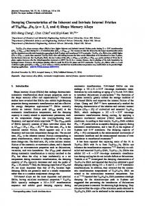
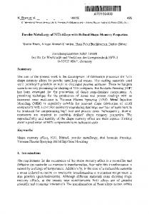
1 INTRODUCTION The interest on smart materials such as shape memory alloys (SMAs), piezoelectric ceramics, electroactive polymers (EAPs) and electrorheological (ER) fluids has grown in the last decades due to their unique properties. This class of materials has the ability of changing its shape, size, stiffness, among other properties, through the imposition of electrical, electromagnetic, temperature or stress fields. In particular, SMAs are metallic alloys that are able to recover their original shape when subjected to the appropriate thermal process: at low temperature martensite (M) phase, the crystalline structure of a SMA is quite malleable and can be easily deformed into new arrangements, which are retained. Upon heating, the crystalline structure returns, in a high temperature austenite (A) phase, to a “memorized” configuration (Fig. 1).
Figure 1 Schematic of M→A and A→M transformations, after [1]. The M→A and A→M transformations are essentially characterized by four temperatures: As and Af are the start and finish temperatures for the A phase, respectively, while Ms and Mf are the start and finish temperatures for the M phase, respectively. As seen, SMAs show a significant hysteresis during both transformations. Using SMAs provides an interesting actuation principle: compact size, high power/ weight ratio, extremely high fatigue resistance to cyclic operation and smooth, clean, spark-free and noiseless performance [2]. These remarkable properties have been attracting growing interest in several fields of sciences and engineering.
Contact author: Ramiro Velázquez1, Edwige E. Pissaloux2 1
Fracc. Rústicos Calpulli. C.P. 20290, Aguascalientes, Mexico, E-mail:
[email protected]
2
Pyramide tour 55, 4 place Jussieu, 75252 Paris Cedex 05, France, E-mail:
[email protected] 1
ISSN 1590-8844 International Journal of Mechanics and Control, Vol. 13, No. 02, 2012
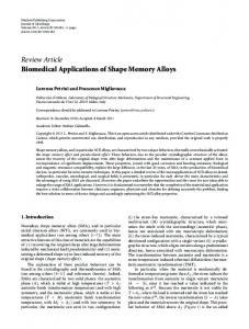
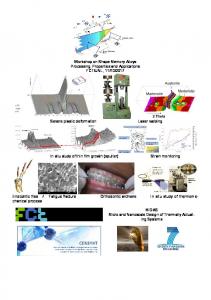
excessive electrical power has the capacity to overheat the SMA, causing thermal stress fatigue and a gradual degradation of its performance. Some micro-structural observations performed in a previous work [9] show that SMAs are in fact very sensitive to overheating. Fig. 3 compares the microstructures of a Nitinol (NiTi) SMA before and after thermal fatigue. Fig. 3(a) shows the surface of a brand new NiTi SMA wire. Note that the material presents a particular homogeneity in its structure. Fig. 3(b) shows the surface of the same specimen right after 20 overheating cycles. Note that overheating actually induces micro-structural modifications: a new granular order is observed in SMAs. Fig 3(c) shows the surface of the same specimen after 50 overheating cycles. Note that the granular distribution becomes more accentuated with bigger and more defined grains. As suggested in [10], SMAs exhibit a strong dependence between grain size and performance: as the grain size increases, the strength of the material decreases. To avoid thermal fatigue, a strategy for rapid electrical heating that avoids overheating must be adopted. This paper presents a simple analytical model to predict the SMA thermal behaviour and compares the performance of a set of controllers designed to increase actuation speed and avoid overheating. The rest of the paper is organized as follows: Section 2 introduces the SMA thermal dynamics and discusses the main parameters characterization. Section 3 presents the design and performance of several temperature controllers while Section 4 discusses some practical considerations for these controllers. Finally, Section 5 concludes the paper summarizing main concepts and results.
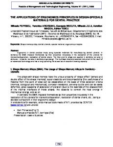
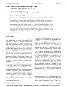
Figure 2 SMA-based devices - (top) Biomedical field: orthodontic wire and endoscope for intestinal exploration. (middle) Robotics field: four-fingered robot hand and portable tactile display for the blind. (bottom) MEMS field: micro-gripper and micro-mirror. SMAs have become successful for biomedical applications due to their excellent bio-compatibility and non-invasive properties. They have been employed in orthodontic devices [3], surgical instruments such as endoscopes [4], among other applications (Fig. 2 top). Robotics is another popular application field for SMAs. Basically, they are used as actuators that expand and stretch creating linear movement. Robotic hands [5], tactile displays [6], among other devices have been developed using SMAs (Fig. 2 middle). SMAs are also used as actuators in microelectromechanical systems (MEMS). Micro-grippers [7] and micro-mirrors [8] are some examples of SMA-based MEMS (Fig. 2 bottom). Although their attractive properties, SMAs have two major drawbacks: their relatively slow response speed and their non-linear behaviour due to the hysteresis shown in fig. 1. The limiting factors on the speed of SMAs are the heating and cooling rates. The cooling rate can be increased by various means such as forced-air convection, oil or water cooling. For heating, practically any source of heat producing a temperature change in the material and/or its surrounding medium can be used: electrical current, Peltier effect, laser, hot air, hot fluid, etc. When electrically driven, the heating rate can only be increased by passing a larger current through the SMA. In principle, an SMA can be heated arbitrarily quickly by passing a sufficiently large current through it. However,
(b)
(a)
(c) Figure 3 Comparison between the micro-structures of NiTi SMAs before and after thermal fatigue due to overheating. 2
ISSN 1590-8844 International Journal of Mechanics and Control, Vol. 13, No. 02, 2012
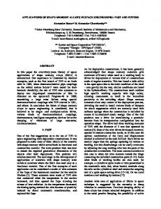
2 MODELLING THE THERMAL DYNAMICS OF SMAs Extensive work has been devoted to model the SMA behaviour. Approaches range from atomic interactions [11], [12] and thermodynamic formulations [13], [14] to phenomenological models based on experimental data [15], [16]. Models agree, regardless of their approach, that a SMA element can be considered as a three-element system in which thermal energy is converted into mechanical work (Fig. 4). In spite of their high quality, most of these models are difficult to use in practice: they lead to quite complex mathematical equations that require burdensome numerical solution. Moreover, they involve parameters not clearly identified and depend on previously determined experimental data, which results totally impractical for rapid evaluation or design. This section discusses the main features associated with SMA thermal modelling through existing constitutive models suitable for easy analytical prediction of the SMA behaviour: they use only the geometry of the SMA element and few material properties extracted from the manufacturer's data sheets or from the literature.
Figure 4 SMA block diagram model. Being a metallic alloy, Qconduction is usually neglected by assuming that the temperature is uniform in the material at all times due to its low internal resistance to heat conduction. A fast method to evaluate when Qconduction can be neglected is the Biot number defined by:
Bi
CV
Recall that, in classical theory of convective heat transfer, the heat-exchange coefficient h is defined by:
h
N u
(6)
l
where is the thermal conductivity of the convective medium (gas or fluid) and Nu is the Nusselt number which defines the heat-exchange ratio given the conditions of convection (free or forced). For free convection, Nu is typically expressed as [17]:
(1)
1 0.387(Gr Pr ) 6 NU 0.6 8 9 27 16 1 (0.559 / Pr )
(2)
where i is the electrical current applied and R is the element's electrical resistance. For most applications (those within the atmosphere), Qradiation can be neglected. Concerning Qconvection, it can be expressed as:
Qconvection hs (T Te )
(5)
2.2 HEAT-EXCHANGE COEFFICIENT
where is the density of the SMA, C is its specific heat, V is the volume of the SMA material and T is the temperature of the SMA at a time t. For electrically driven SMAs, heat is generated in accordance with the Lenz-Joule law:
Qs i 2 R
dT i 2 R hs(T Te ) dt
The block diagram model of the SMA thermal behaviour is shown in fig. 5.
Let us start analyzing the SMA thermal behaviour considering a system in thermal equilibrium where Qs is the heat generated by an external source and Qconduction, Qconvection and Qradiation are the different dissipation forms of heat. From this thermal balance, the heat stored in the SMA can be expressed using the classical differential equation of heat transfer as follows:
dT Qs Qconduction Qconvection Qradiation dt
(4)
where l is the characteristic length of the SMA material and k is its thermal conductivity. If Bi is less than 0.01, then this assumption is considered valid. Once the Biot number has been validated, eq. (1) becomes:
2.1 THERMAL MODEL
CV
hl k
2
(3)
where h is the heat-exchange coefficient between the SMA and the surrounding medium, S is the surface area of the SMA and Te is the environment's temperature.
Figure 5 Functional block diagram of the SMA thermal behaviour. 3
(7)
ISSN 1590-8844 International Journal of Mechanics and Control, Vol. 13, No. 02, 2012
where Pr and Gr are the Prandtl and Grashof numbers for the convective medium, respectively. Concerning the characteristic length l, it is commonly defined as the volume of the material divided by its surface area (l=V/S). However, in the case of thin metallic cylinders or wires (a particularly popular shape in SMAs), it is more pertinent to consider the characteristic length equal to the cylinder's diameter (l=d). 2.3 SIMULATION RESULTS As illustrative example, consider a NiTi SMA wire of 200 m diameter and 7 mm length. The thermal properties of NiTi, directly extracted from the manufacturer's data sheets [18], as well as the air properties of interest for this study are given in table I. The rest of the parameters needed for simulation are also shown in table I. They can either be calculated from those in table I or easily measured through simple experiments. Being the Biot number valid, eq. (5) can be used. Fig. 6 shows the time response of the NiTi wire to a step current of 300 mA. Recall that, once temperature achieves Af, the transformation is complete and the SMA has recovered its memorized shape. Any additional heat supplied to the SMA is useless and overheats the material. Furthermore, the SMA's response becomes problematic: as frequency increases, the cooling rate decreases significantly enough so that the A→M transformation cannot be completed. The SMA goes into saturation and the memory effect is no longer observed. Fig. 7 shows the time response of the Niti wire to a 1 Hz, 300 mA square signal. Note that Mf is never achieved.
Figure 6 Temperature-time response to a step input current of 300 mA.
Figure 7 Response to a 1 Hz, 300 mA square signal.
Table I - Geometric/thermal properties of NiTi and surrounding medium. Property Value Unit NiTi properties 6450 kg·m-3 Density Specific heat C 320 J·kg-1·K-1 Thermal conductivity k 8 W·m-1·K-1 Transformation temperatures 78, 68, 52, 42 °C Af, As, Ms, Mf Air properties (20°C) 0.0257 W·m-1·K-1 Thermal conductivity Grashof number Gr 0.3903 0.713 Prandtl number Pr Calculated/measured properties Surface S 4.46x10⁻⁶ m2 -10 Volume V 2.2x10 m3 0.739 Nusselt number Nu m Characteristic length l 200x10-6 Heat-exchange coefficient h 94.96 W·m-2·K-1 Resistance R 3 20 °C Environment’s temperature Te
2.4 PHASE TRANSFORMATION Unfortunately, the actual SMA thermal behaviour is more complex. As seen in fig. 1, SMAs, unlike traditional materials, show hysteresis during both M→A and A→M transformations. Physically, these hystereses are a dissipation and assimilation of latent heat due to phase transformation that tend to slow down both heating and cooling processes. Consequently, it is pertinent to evaluate this effect on the thermal dynamics. A successful empirical relation has been proposed by Liang and Rogers [1], which describes the amount of martensite fraction ξ transformed on a temperature T. For constant load conditions, ξ can be written for heating as: at T A 0 f T As 1 (T ) cos 1 at As T A f 2 A f As at T A 1 s
4
(8)
ISSN 1590-8844 International Journal of Mechanics and Control, Vol. 13, No. 02, 2012
where t2 is the time to reach Ms (i.e. before transformation starts). Simplified analytical methods for solving eq. (9) do exist in the literature [19], [20] and might be more practical, faster and easier to implement. Fig. 8 shows the delay effect due to phase transformation on the thermal response of the 200 m diameter wire to a step current of 300 mA. The latent heat of transformation H was assumed to be 14 J/g, a typical value in NiTi SMAs. Note that the effect of phase transformation moderately extends the heating time, but significantly increases the cooling one. Fig. 9 shows the time response to a set of step currents applied to the 200 m NiTi wire. The amplitude is varied from 200 to 800 mA. Note that the greater the current, the less the influence of the latent heat on the actuation time. It can be concluded that the delay effect due to phase transformation can be reasonably neglected especially for input current intensities higher that 800 mA. Thus, the SMA thermal behaviour can be simplified to a linear model and the functional block diagram of fig. 5 can be retained.
The analogous dependence can be expressed for cooling by replacing As and Af temperatures with Mf and Ms temperatures correspondingly. Eq. (8) completes the energy balance eq. (5) with the phase transformation parameter as follows:
d dT i 2 R hS (T Te ) dt dt
V C
(9)
where H is the latent heat defined on the transformation interval. Solution of eq. (9) can be obtained using any scientific computing software such as Maple (Maplesoft Co.) or Mathematica (Wolfram Research). For example, the analytical solution for heating in As