... RpÃq, we denote with â the Kronecker product A â B â RnpÃmq. ...... In Springer Handbook of Robotics, pages
Modelling, Estimation and Identification of Humanoid Robots Dynamics
DIC
Silvio Traversaro
ISTITUTO ITALIANO DI TECNOLOGIA
Supervisor: Dott. Francesco Nori Fondazione Istituto Italiano di Tecnologia Genova, Italia 2017
Abstract During the last fifty years, the scientific community has dealt with the problem of designing humanoid robots, with the goal of creating artificial machines flexible enough to master any task performed by a human. A prerequisite for such generic machines would be the ability to control the forces that robots exchange with the environment, in addition to their own motion. These requirements imply that any controller of a humanoid robot requires an implicit or explicit model for the robot’s dynamics, i.e. the laws describing the relation between the robot motion and the forces applied on itself, being either the external forces that the robot exchange with the environment or the forces provided by its own motors. Additionally, any time-variant quantity present in these models need to be perceived by the humanoid robot. If a quantity is not directly measured by a sensor, it needs to be estimated using the available measurements of different quantities and the dynamical models that relate them. Both the dynamics models and the sensor models are typically not perfectly known, and need to be identified from measured data and using a set of a-priori hypothesis. This thesis focuses on addressing the problems of modelling, estimation and identification of humanoid robots, focusing in particular to the specific characteristics and sensor set of the iCub humanoid robot.
Acknowledgements A tutti (scusate se dimentico qualcuno): . . . grazie.
The first group of people I would like to thank are the one that I consider my “scientific mentors”, the one without which this thesis simply would not exists. The first one is Andrea Del Prete, that I first met during my Master’s studies, and with which I had the luck of working while preparing my Master’s Thesis and before starting my PhD. The second one is Francesco Nori, my Master’s and PhD supervisor and the first person in my professional life to trust me with real responsibility. The third one is Daniele Pucci, that was an invaluable companion during my PhD. The fourth one is Alessandro Saccon that I visited in Eindhoven during the end of 2015, and with which I had a lot “open-minding” discussions. I would like to thank also all my other colleagues at the Istituto Italiano di Tecnologia (IIT), firstly Francesco (Romano), Johrabib and Luca with whom I had the lucky to start to work in the group that would later become the Dynamic Interaction Control group at IIT. Furthermore, I would like to thank all other people that joined the Dynamic Interaction Control lab at different stages and in different ways: Talha, Naveen, Francesca, Yue, Prashanth, Claudia, Nuno, Gabriele, Francisco, Marie, Stefano, Matteo, Ali, Joan, Marta, Maria and Diego. Your feedback, even when just asking question, was invaluable for this thesis. I would also like to thanks are the amazing crew that before I joined IIT and during the years built and maintained the iCub robot and all the related infrastructure. Ugo, Randaz, Vadim, Lorenzo, Daniele, Ali, Giorgio, Maggia, Stefano, Alberto, Marco, Valentina, Julien, Spada, Gesino, Masa, Marcello were for me an example of dedication. Trying to be at their level has always been a great motivation to always learn more and work harder. i
I would like to thank who in this years took care that I was coming to work everyday: Francesco, Raffaello and Cive when commuting by car, and Anand, Giovanni and Emy when living in Genoa. I would like to thank Benni, Titti and One. I would also like to thank the parish I have grown up in, Santo Stefano del Ponte, and everyone I met related to that. All those experiences thought me the few things I know about trying to care for any human being, a fundamental skill for any job. I would also like to thank my family, my sister Marta, my parents Caterina and Gian Renzo, my aunt Anna and my grandparents Angelina, Guido, Olga and Silvio. In the deepest sense, this thesis would have never been written if it was not for them. Last, I would like to thank Camilla (or Cami, as she prefers to be called). The kind of gratitude I have towards her is simply not fit to print in this thesis.
ii
Contents 1 Introduction 1.1 iCub Humanoid Robot . 1.2 Thesis Organization . . 1.2.1 Modelling . . . . 1.2.2 Estimation . . . 1.2.3 Identification . . 1.3 Technological Outcome .
. . . . . .
. . . . . .
. . . . . .
. . . . . .
. . . . . .
. . . . . .
. . . . . .
. . . . . .
. . . . . .
. . . . . .
. . . . . .
. . . . . .
. . . . . .
. . . . . .
. . . . . .
. . . . . .
. . . . . .
. . . . . .
2 Rigid Body 2.1 Overview of the notation . . . . . . . . . . . . . . . . . . 2.2 Math preliminaries . . . . . . . . . . . . . . . . . . . . . 2.3 Frame kinematics . . . . . . . . . . . . . . . . . . . . . . 2.3.1 Rigid Body Assumption . . . . . . . . . . . . . . 2.3.2 Points and coordinate frames . . . . . . . . . . . 2.3.3 6D Velocity vectors . . . . . . . . . . . . . . . . . 2.3.4 Adjoint matrix as a change of frame . . . . . . . 2.4 Frame acceleration . . . . . . . . . . . . . . . . . . . . . 2.4.1 The cross product on R6 (×) . . . . . . . . . . . 2.4.2 Acceleration representations and their relation . 2.4.3 “Sensor” acceleration . . . . . . . . . . . . . . . 2.4.4 “Proper” acceleration . . . . . . . . . . . . . . . 2.4.5 Illustrative Example: the Spinning Wheel . . . . 2.5 Force-Torque covectors . . . . . . . . . . . . . . . . . . . ¯ ∗) . . . . . . . . 2.5.1 The dual cross product on R6 (× 2.6 Rigid Body Dynamics . . . . . . . . . . . . . . . . . . . 2.6.1 Review of Lagrangian Dynamics: the point mass 2.6.2 Rigid Body Lagrangian Dynamics . . . . . . . . 2.7 Newton-Euler equations in the different representations 2.7.1 Left-trivialized . . . . . . . . . . . . . . . . . . .
iii
. . . . . .
. . . . . . . . . . . . . . . . . . . .
. . . . . .
. . . . . . . . . . . . . . . . . . . .
. . . . . .
1 1 6 6 6 6 7
. . . . . . . . . . . . . . . . . . . .
8 9 10 12 12 12 14 16 18 18 19 19 19 21 25 26 27 28 30 35 35
2.8
2.7.2 2.7.3 2.7.4 Rigid
Right-trivialized . . . . . . . Mixed . . . . . . . . . . . . . Sensor . . . . . . . . . . . . . Body Total Momentum and its
. . . . . . . . . . . . . . . . . . . . . . . . . . . . . . . . . . . . . . . . . . relation with Dynamics
35 35 36 36
3 Multi Body 38 3.1 Composition of relative and absolute velocity . . . . . . . . . 39 3.2 Joints . . . . . . . . . . . . . . . . . . . . . . . . . . . . . . . 40 3.2.1 One Degree of Freedom Joints . . . . . . . . . . . . . 41 3.2.2 Fixed joints . . . . . . . . . . . . . . . . . . . . . . . . 43 3.3 Modelling of Multibody Systems . . . . . . . . . . . . . . . . 43 3.3.1 Topology . . . . . . . . . . . . . . . . . . . . . . . . . 44 3.3.2 Numbering . . . . . . . . . . . . . . . . . . . . . . . . 46 3.3.3 Shape . . . . . . . . . . . . . . . . . . . . . . . . . . . 47 3.4 Relative Forward Kinematics . . . . . . . . . . . . . . . . . . 47 3.5 Multibody Lagrangian Dynamics . . . . . . . . . . . . . . . . 49 3.5.1 Absolute State definition . . . . . . . . . . . . . . . . 49 3.5.2 Kinematics . . . . . . . . . . . . . . . . . . . . . . . . 50 3.5.3 Multibody Lagrangian . . . . . . . . . . . . . . . . . . 52 3.6 Base Change of Variables . . . . . . . . . . . . . . . . . . . . 55 3.7 Free Floating Dynamics with different representations or the base velocity . . . . . . . . . . . . . . . . . . . . . . . . . . . 56 3.7.1 Left-trivialized . . . . . . . . . . . . . . . . . . . . . . 57 3.7.2 Right-Trivialized . . . . . . . . . . . . . . . . . . . . . 58 3.7.3 Mixed . . . . . . . . . . . . . . . . . . . . . . . . . . . 58 3.8 Free Floating Dynamics with different base links . . . . . . . 59 3.9 System state transformation providing centroidal dynamics . 60 3.9.1 Frames not rigidly attached to a link . . . . . . . . . . 61 3.9.2 Recalls on centroidal dynamics quantities . . . . . . . 62 3.9.3 Average 6D Velocity . . . . . . . . . . . . . . . . . . . 63 3.9.4 Centroidal change of variables . . . . . . . . . . . . . . 64 3.10 Proofs . . . . . . . . . . . . . . . . . . . . . . . . . . . . . . . 67 3.10.1 Proof of Theorem 3.3 . . . . . . . . . . . . . . . . . . 67 3.10.2 Proof of Lemma 3.11 . . . . . . . . . . . . . . . . . . . 68 4 Contact Force-Torques and Internal Torques Estimation 4.1 Introduction . . . . . . . . . . . . . . . . . . . . . . . . . . . 4.2 State of art . . . . . . . . . . . . . . . . . . . . . . . . . . . 4.2.1 Joint torques estimation . . . . . . . . . . . . . . . . 4.2.2 External force-torque position estimation . . . . . . iv
. . . .
71 71 72 72 73
4.3
4.4
4.5
4.6 4.7
4.8
4.2.3 External force-torque intensity estimation . . . . . . . Sensor Models . . . . . . . . . . . . . . . . . . . . . . . . . . . 4.3.1 Joint Sensors . . . . . . . . . . . . . . . . . . . . . . . 4.3.2 Link Sensors . . . . . . . . . . . . . . . . . . . . . . . Estimation of the net force-torque . . . . . . . . . . . . . . . 4.4.1 Example: rigid body external force-torque estimation 4.4.2 Sensor based estimation . . . . . . . . . . . . . . . . . 4.4.3 Kinematic based estimation . . . . . . . . . . . . . . . 4.4.4 Hybrid estimation . . . . . . . . . . . . . . . . . . . . Multibody External Force-Torque Estimation . . . . . . . . . 4.5.1 Force-Torque Sensors Induced Submodel Decomposition 4.5.2 External Force-Torque Estimation . . . . . . . . . . . 4.5.3 Estimation of external forces acting on multiple link in a submodel . . . . . . . . . . . . . . . . . . . . . . . Joint Torques Estimation . . . . . . . . . . . . . . . . . . . . 4.6.1 Example of torque estimation . . . . . . . . . . . . . . Six-Axis Force-Torque Sensors Model-based Offset Calibration 4.7.1 Offset Calibration with the external forces acting on a Single Link . . . . . . . . . . . . . . . . . . . . . . . Proofs . . . . . . . . . . . . . . . . . . . . . . . . . . . . . . . 4.8.1 Proof of Theorem 4.1 . . . . . . . . . . . . . . . . . . 4.8.2 Proof of Theorem 4.2 . . . . . . . . . . . . . . . . . .
74 75 75 75 77 77 79 79 80 80 80 81 83 84 86 87 87 88 88 88
5 Six 5.1 5.2 5.3
Axis Force Torque Sensors In Situ Calibration 90 Introduction . . . . . . . . . . . . . . . . . . . . . . . . . . . . 90 Problem statement and assumptions . . . . . . . . . . . . . . 94 In Situ Calibration Methods . . . . . . . . . . . . . . . . . . . 95 5.3.1 The geometry of the raw measurements . . . . . . . . 95 5.3.2 Method for estimating the sensor’s offset . . . . . . . . 96 5.3.3 Method for estimating the sensor’s calibration matrix 99 5.4 Experimental Results . . . . . . . . . . . . . . . . . . . . . . . 102
6 Rigid Body Inertial Parameters Identification 109 6.1 Introduction . . . . . . . . . . . . . . . . . . . . . . . . . . . . 109 6.2 Background on Rigid Body Inertial Parameters . . . . . . . . 111 6.2.1 Rigid Body Dynamics . . . . . . . . . . . . . . . . . . 111 6.2.2 Inertial parameters . . . . . . . . . . . . . . . . . . . . 112 6.2.3 Relationship between the inertial parameters and the density function . . . . . . . . . . . . . . . . . . . . . 112 6.2.4 3D Inertia at the Center of Mass and Principal Axes . 113 v
6.3
6.4
6.2.5 Inertial Parameters Identification . . . . . Full Physical Consistency . . . . . . . . . . . . . 6.3.1 Full physical consistency . . . . . . . . . . 6.3.2 Full physical consistent parametrization of rameters . . . . . . . . . . . . . . . . . . . Experimental Results . . . . . . . . . . . . . . . . 6.4.1 Optimization on Manifolds . . . . . . . . 6.4.2 Experiments . . . . . . . . . . . . . . . .
. . . . . . . . . . . . inertia . . . . . . . . . . . . . . . .
7 Multi Body Inertial Parameters Identification 7.1 Introduction . . . . . . . . . . . . . . . . . . . . . . . . . 7.2 Identification of floating base dynamics . . . . . . . . . . 7.3 Inertial Parameter Identification and Torque Estimation 7.4 Experimental results . . . . . . . . . . . . . . . . . . . . Appendices
. . . . . . . . . pa. . . . . . . . . . . .
. . . .
. . . .
. . . .
115 115 115 116 118 118 120 123 123 125 128 130 148
A Mathematical background on Lie group formalism 149 A.1 Matrix Lie Groups . . . . . . . . . . . . . . . . . . . . . . . . 149 A.1.1 Matrix Lie Group Examples . . . . . . . . . . . . . . . 153 A.2 Multibody Dynamics Notation and its connection to Lie Groups156 A.2.1 Frame Pose and 6D Velocity . . . . . . . . . . . . . . 156 A.2.2 Cross Product on R6 . . . . . . . . . . . . . . . . . . . 156 ¯ ∗ ) . . . . . . . . . . . 157 A.2.3 The dual cross product on R6 (× A.3 Euler-Poincar´e Equations and Rigid Body Dynamics . . . . . 157 A.3.1 Euler-Poincar´e Equations . . . . . . . . . . . . . . . . 158 A.3.2 Rigid Body Dynamics . . . . . . . . . . . . . . . . . . 159 A.4 Hamel Equations and Multi Body Dynamics . . . . . . . . . . 160 A.4.1 Hamel Equations . . . . . . . . . . . . . . . . . . . . . 160 A.4.2 Multi Body Dynamics . . . . . . . . . . . . . . . . . . 161
vi
Chapter 1
Introduction 1.1
iCub Humanoid Robot
The main robotic experimental platform used in this thesis is the iCub robot, developed by the iCub Facility at the Italian Institute of Technology. It is a child-sized humanoid robot originally developed by the RobotCub European Project for research in embodied cognition [Sandini et al., 2004]. Since its initial release in 2006, the iCub has been continuously updated with improvements and new features. iCub’s copies it have been distributed to more then 30 partners institution in Europe, Asia and United States. As the improvements are continuously released and integrated into the different iCub’s, all the copies of iCub have different features, depending on their release date, the maintenance’s updates performed during the years and specific customization of each iCub. In the following we discuss the characteristic relevant to this thesis, that apply to the latest “standard” version of iCub, informally referenced hereafter as iCub 2.5, as of the beginning of 2017. The iCub is a 53 degrees-of-freedom (DOF) humanoid robot. The DOFs are distributed as in the following: 6 for each leg, 3 for the torso, 6 for the head and eyes, 7 for each arm and 9 for each hand. One additional servo motor is used to open and close the eye-lids. In this thesis we consider only a subset of 32 DOFs (legs, torso, arms and neck) that are actuated with Brushless DC electric motor (BLDC) with an Harmonic Drive transmission, making them suitable for joint torque control. More details on the actuation and mechanics of the iCub 2.5 can be found in [Parmiggiani et al., 2012].
1
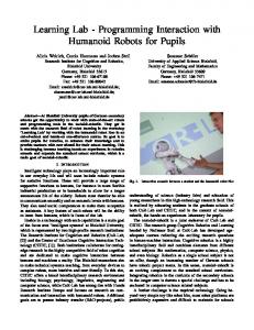
Fig. 1.1 The iCub version 2.5, balancing itself on one foot thanks to contact forces control.
One of the research goals of the iCub project is to endow humanoids with advanced physical interaction capabilities. This is motivated by the idea that future robots will be required to physically interact with the environment and, in the long run, with humans. A key requirement for this interaction control is the capability to measure and control the forces that a robot is exchanging with its environment, i.e. contact forces control. While in traditional industrial applications this is achieved by by placing a sixaxis force-torque sensor between the robot and the environment, this is not feasible in humanoid robotics, in which the contact location is typically not known a-priori. To overcome this limitations, a unique set of dynamics2
related sensors have been added during the years to the iCub.
Fig. 1.2 Distribution of the six embedded six-axis force-torque sensors (green) available in iCub 2.5 . The main force sensors available on the iCub are six internal six-axis force-torque sensors. Four of them are mounted at the base of each limb while two of them are mounted in feet right below the ankles. The locations of these sensors are highlighted in Figure 1.2. The placement of these sensors was dictated by practical reasons, as the hand structure would have not been not able to support a force-torque sensor mounted in it, but also to enable estimation of internal joint torques and external force-torque, as described in [Fumagalli et al., 2010b] for a single limb and in Chapter 4 of this thesis for the whole-body case. While internal force-torque sensors are able to measure force-torque due 3
Fig. 1.3 Distribution of the tactile sensors on iCub 2.5. to a combination of internal dynamics and of contact wrenches, they are in general unable to measure the location of a contact force, or its distribution over a contact surface. For addressing these concerns the iCub body has been covered with a distributed set of capacitive elements acting as tactile sensors [Maiolino et al., 2013]. The entire sensor network acts as an “artificial skin”, constituted by a sandwich of different flexible fabrics mounted on top of a flexible Printed Circuit Board (PCB), so that the entire structure can be conformed on surfaces of different curvatures. The majority of iCub 2.5 external surface has been covered by this “skin”, as shown by Figure 1.3.
4
Fig. 1.4 Distribution of the inertial sensors i.e. gyroscopes (left) and accelerometers (right) in iCub 2.5 . To read the distributed tactile sensors, the iCub has been equipped with distributed network of dedicated electronic boards. Remarkably, this boards are equipped with a 3 Degree-of-Freedom (DOFs) accelerometer. Similarly, several motor control boards are distributed in the robot structure, and each motor control board is equipped with both a 3 DOFs accelerometer and a 3 DOFs gyroscops. Furthermore, an full-fledged Inertial Measurement Unit, equipped with a 3 DOFs magnetometer, accelerometer and gyroscope is mounted on the head of the robot. These arrangements, shown in Figure 1.4 provides the iCub with a vast amount of distributed inertial sensing, that has been exploited for fine calibration [Guedelha et al., 2016]. These sensors form the basis for the use of the estimation and identification algorithms presented in the thesis, that are essential technologies to enable interaction force control. To describe the presented algorithms, we need to provide a solid background in multibody dynamics, that will be also presented in the thesis.
5
1.2
Thesis Organization
The following is a brief summary of the organization of the thesis. At the beginning of each chapter a discussion of the contribution with respect to the state of art of the specific chapter is given.
1.2.1
Modelling
This thesis includes in the Chapters 2, 3 a self-contained derivation of the multi body dynamics and in Appendix A its connection with Lie Groups theory. Particular focus is placed on the role of the base link in free-floating dynamics, and in the different representation of base-related quantities that are used in literature. This chapters form the theoretical basis for the rest of the thesis, devoted to estimation and identification of humanoid robot dynamics.
1.2.2
Estimation
Chapter 4 describes the algorithms used for the estimation of external forces and internal joint torques using internal six-axis force-torque sensors, distributed inertial sensing and a distributed tactile system, that are the set of sensors available on the iCub robot, as discussed in Section 1.1. This part is mainly a generalization of already existing results [Fumagalli et al., 2010c, Ivaldi et al., 2011, Fumagalli et al., 2012, Del Prete et al., 2012] to the whole-body case.
1.2.3
Identification
The main contribution of Chapter 5 are two new algorithms for calibration of six-axis force-torque sensors that can be performed in situ, i.e., without removing the sensor from the hosting system. These algorithms exploit the specific geometric of the gravity force-torque when expressed in the sensor frame. Chapter 6 introduces the concept of the identification of the inertial parameters of a single rigid body. The main contribution of this chapter is the definition of a new condition, the fully physical consistency for a set of inertial parameters to determine if they can be generated by a physical rigid body. The proposed condition ensure both the positive definiteness and the triangular inequality of 3D inertia matrices as opposed to existing techniques in which the triangular inequality constraint is ignored.
6
Chapter 7 generalize the identification problem to the case of a system compose by multiple rigid bodies, with particualr attention of the relations between the identifiability subspaces of the regressor associated with the different set of sensors. The main contribution of this chapter is the adaptation of the existing techniques for inertial parameters identification on humanoids to the specific set of sensors that is available on the iCub robot. While most existing techniques [Ayusawa et al., 2014, Ogawa et al., 2014, Mistry et al., 2009] assume that either the contact forces or the joint torques measurement are available, in the iCub we only have a distributed tacticle system and a internal six-axis force-torque sensors. We propose a way of using internal six-axis force-torque sensor for estimation, and furthermore we demonstrate that the set of inertial parameters that are identifiable from the internal six-axis force-torque sensors are a superset of the one that we need to run the estimation algorithms presented in Chapter 4.
1.3
Technological Outcome
The modelling formalism and the estimation algorithms presented in this thesis enabled the development of an whole-body controller on the iCub robot, that has been used to showcase highly dynamical balancing [Pucci et al., 2016b] and has even permitted to the iCub to take part to an Italian Talent show as a participant [Talent, 2016]. The interested reader is referred to [Nori et al., 2015] for an integration paper describing the overall wholebody control architecture. Furthermore, all the algorithms described in this thesis have been implemented in the open source C++ library iDynTree [Traversaro et al., 2017]. The iDynTree is complete with documentation for installing it and using it. Furthermore, the library is equipped with bindings with MATLAB, Octave, Python, Lua and Java to enable its use in a wide set of platforms, fulfilling all the disparate needs that may arise in a research environment.
7
Chapter 2
Rigid Body In this chapter we introduce the dynamics of a rigid body. Existing (robotrelated) literature on rigid body dynamics can be divided into two main categories. The first category contains work that use almost exclusively spatial 6D velocities as defined in Geometrical Mechanics such as [Featherstone, 2008, Featherstone and Orin, 2016, Jain, 2010, Murray et al., 1994]. The second category include work that use the 6D velocities that are a combination of the “classical” linear velocity and the angular velocity of the body [Spong et al., 2006, Siciliano et al., 2008, Chiaverini et al., 2016]. The connection between these two representations is well known to robotics researcher [Murray et al., 1994, Bruyninckx and De Schutter, 1996, Englsberger, 2016], but it was never explored in depth. Furthermore, it is a common source of confusion for newcomers to the field. In this chapter we treat all the commonly used representation of velocity, explaining the respective advantages and limitations, and the effect of choosing one representation or another on dynamics. Furthermor, while most robotics textbooks on dynamics introduce the Newton-Euler equations as a given, we prefer to derive them from the basic principle of Lagrangian Dynamics. This methodology is consistent with what is typically done for fixed-based robots [Siciliano et al., 2008, Spong et al., 2006], and is useful to get an insight on the structure of NewtonEuler equations and why they are different from the classical Euler-Lagrange equations that describe the evolution of a system whose configuration space is a vector space. The goal of this chapter is two-folded: while introducing the kinematics and dynamics of the rigid body, we also introduce a notation for describing kinematics and dynamics 6D quantities, as well as their coordinate trans-
8
formations. The goal of this newly introduced notation is to be compact, not ambiguous, and in harmony with Lie Group formalism. The notation borrows from the well known notation introduced in [Featherstone, 2008], which is also used, with slight modifications, in [Featherstone and Orin, 2016]. This notation is, unfortunately, not fully in accordance with Lie group formalism used in, e.g., [Murray et al., 1994, Park et al., 1995, Kim, 2012], that is, however, less compact than [Featherstone, 2008], leading to long expressions when several rigid bodies are present. This chapter presents the frames notation, while the connection between the notation and the Lie group formalism is presented in Appendix A.
2.1
Overview of the notation
Remark 2.1. Every chapter will begin with an overview of the notation used in that Chapter. Frequently, the notation used in a given chapter will be a simplified version of the full notation introduced in this chapter, to avoid overloading the text with an extremly complex notation. In some cases, the simplified notation can only be introduced for a single section. In that case, an overview of the simplified notation used in that section will open the section.
9
2.2
Notation used through the thesis A,B coordinate frames p an arbitrary point oB origin of B [A] orientation frame associated to A B[A] frame with origin oB and orientation [A] Ap coordinates of p w.r.t. to A Ao coordinates of oB w.r.t. to A B AH homogeneous transformation from B to A B AX velocity transformation from B to A B Cv 6D velocity expressing the velocity of B wrt A,B to A written in C C v∧ 4 × 4 matrix representation of C vA,B A,B Cv 6 × 6 matrix representation of the 6D velocity A,B × cross product ∗ Cv ¯ 6 × 6 matrix representation of the dual cross A,B × product coordinates of the 6D force f w.r.t. B Bf B X 6D force transformation from B to A A
B � f, v pairing between 6D force and velocity B A,B 6 × 6 inertia tensor of link (=rigid body) L B ML expressed with respect to frame B
Math preliminaries
The following notation is used throughout the thesis. • The set of real numbers is denoted by R. Let u and v be two ndimensional column vectors of real numbers, i.e. u, v ∈ Rn , then their inner product is denoted as uT v, with “T ” the transpose operator. • The identity matrix of dimension n is denoted In ∈ Rn×n ; the zero column vector of dimension n is denoted 0n ∈ Rn ; the zero matrix of dimension n × m is denoted 0n×m ∈ Rn×m . • The set SO(3) is the set of R3×3 orthogonal matrices with determinant equal to one, namely SO(3) := { R ∈ R3×3 | RT R = I3 , det(R) = 1 }. 10
(2.1)
• The set so(3), read little so(3), is the set of 3 × 3 skew-symmetric matrices, so(3) := { S ∈ R3×3 | S T = −S }. • The set SE(3) is defined as � o n� R p ∈ R4×4 | R ∈ SO(3), p ∈ R3 . SE(3) := 01×3 1 • The set se(3) is defined as � o n� Ω v ∈ R4×4 | Ω ∈ so(3), v ∈ R3 . se(3) := 01×3 0
(2.2)
(2.3)
(2.4)
• Given the vector w = (x; y; z) ∈ R3 , we define w∧ (read w hat) as the 3 × 3 skew-symmetric matrix ∧ 0 −z y x 0 −x ∈ so(3). (2.5) w∧ = y := z −y x 0 z Given the skew-symmetric matrix W = w∧ , we define W ∨ ∈ R3 (read W vee) as ∨ 0 −z y x 0 −x := y ∈ R3 . W∨ = z (2.6) −y x 0 z Clearly, the vee operator is the inverse of the hat operator. • Given a vector v = (v; ω) ∈ R6 , v and ω ∈ R3 , we define � �∧ � ∧ � v ω v v∧ = := ∈ se(3). ω 01×3 0
(2.7)
• Similarly to what was done for vectors in R3 few lines above, we define the vee operator as the inverse of the hat operator such that � ∧ �∨ � � ω v v := = v ∈ R6 . (2.8) 01×3 0 ω • Given A ∈ Rn×m and B ∈ Rp×q , we denote with ⊗ the Kronecker product A ⊗ B ∈ Rnp×mq . 11
• Given X ∈ Rm×p , vec(X) ∈ Rnm denotes the column vector obtained by stacking the columns of the matrix X. In view of the definition of vec(·), it follows that � � vec(AXB) = B > ⊗ A vec(X). (2.9)
2.3 2.3.1
Frame kinematics Rigid Body Assumption
A rigid body is an idealization of a physical object, in which the deformation internal to the object are assumed to be negligible, i.e. the object is assumed to be nondeformable. While in the real physical world every object that is interacting with the external world is subject to a certain degree of deformation, in the study of certain mechanism such a humanoid robots, the rigid body assumption is useful as it permits to develop model that capture the dominant dynamics of the analyzed system, disregarding any aspect related to the internal compression and decompression of the object composing the system. The kinematics of a rigid body are typically described by attaching to the rigid body a frame, defined as the combination of a point (called origin) and an orientation frame in the 3D space [De Laet et al., 2013, Spong et al., 2006]. For this reason in this section we will describe the kinematics of frames, and this will serve also for describing the kinematics of any rigid body.
2.3.2
Points and coordinate frames
We typically employ a capital letter to indicate a frame. Given a frame A, we will indicate with oA its origin and with [A] its orientation frame. Formally, we write this as A = (oA , [A]). Frames can be time varying. They can be used, e.g., to describe the position and orientation in space of a rigid body as time evolves. They are also used to expressed a coordinate system for a 6D force exchanged by two bodies or used to define a coordinate system to describe a robot task (like a frame attached to the center of mass and oriented as the inertial frame). Newton’s mechanics defines the set of Inertial frames. In this document, we usually indicate one inertial frame as with A (the Absolute frame). As common practice, for robots operating near the Earth surface, we will assume the frame A to be fixed to the world’s surface, disregarding noninertial effects due to the Earth’s motion. 12
Coordinate vector of a point Given a point p, its coordinates with respect to a frame A = (oA , [A]) are collected in the coordinate vector A p. The coordinate vector A p represents → the coordinates of the 3D geometric vector r oA ,p connecting the origin of frame A with the point p, pointing towards p, expressed in the orientation frame [A], that is → → r oA ,p · x A → → A (2.10) p := r oA ,p · y A ∈ R3 , → → r oA ,p · z A →
→
→
with · denoting the scalar product between two vectors and x A , y A , z A , the unit vectors defining the orientation frame [A]. Change of orientation frame Given two frames A and B, we will employ the notation A
RB ∈ SO(3)
(2.11)
to denote the coordinate transformation from frame B to frame A. The coordinate transformation A RB only depends on the relative orientation between the orientation frames [A] and [B], irrespectively of the position of the origins oA and oB . Homogeneous transformation To describe the position and orientation of a frame B with respect to another frame A, we employ the 4 × 4 homogeneous matrix �A � RB A oB A HB := . (2.12) 01×3 1 Given a point p, the homogeneous transformation matrix A HB can be also used to map the coordinate vector A p to B p as follows. Let A p¯ and B p¯ denote the homogenous representation of A p and B p, respectively. That is, let A p¯ := (A p; 1) ∈ R4 and likewise for B p¯ (note that ; indicates row concatenation). Then A
p¯ = A HB B p¯,
(2.13)
which is the matrix form of A p = A RB B p + A oB . We refer the interested readers to [Murray et al., 1994, Chapter 2] for further details on homogeneous representation of rigid transformations. 13
2.3.3
6D Velocity vectors
In the following, given a point p and a frame A, we define A
p˙ :=
d dt
A
� p .
(2.14)
In particular, when p is the origin of a frame, e.g., p = oB , we have A
o˙ B =
d dt
A
� oB .
It is important to note that, by itself, expressions like o˙ B or p˙ have no meaning. Similarly to (2.14), we also define A
d R˙ B := dt
A
RB
�
(2.15)
and A
d H˙ B := dt
A
�
HB =
R˙ B
A o˙
01×3
0
�A
B
� .
(2.16)
The relative velocity between a frame B with respect to a frame A can be represented by the time derivative of the homogenous matrix A HB ∈ SE(3). A more compact representation of A H˙ B can be obtained multiplying it by the inverse of A HB on the left or on the right. In both cases, the result is an element of the se(3) that will be called a 6D velocity. Premultipliying on the left, one obtains �A T � �A � T Ao RB −A RB R˙ B A o˙ B B A −1 A ˙ HB HB = 01×3 1 01×3 0 �A T A � T A o˙ RB R˙ B A RB B = . (2.17) 01×3 0 T AR ˙ B appearing on the right hand side of (2.17) is skew Note that A RB symmetric. Define B vA,B and B ωA,B ∈ R3 so that B
TA vA,B := A RB o˙ B , B ∧ A TA ˙ ωA,B := RB RB .
The left trivialized velocity of frame B with respect to frame A is �B � v B vA,B := B A,B ∈ R6 . ωA,B 14
(2.18) (2.19)
(2.20)
By construction, B ∧ vA,B
−1 A ˙ = A HB HB .
(2.21)
Note the slight abuse of notation in using the hat operator ∧ in (2.19) and (2.21) that maps a vector into its corresponding matrix representation (respectively, from R3 to R3×3 using (2.5) in (2.19) and from R6 to R4×4 using (2.7) in (2.21)). Specularly to what was done in (2.17), right multiplying A H˙ B by the inverse of A HB leads to �� T � �A T Ao −A RB R˙ B A o˙ B A RB B A ˙ A −1 HB HB = 01×3 1 01×3 0 �A A T A � T Ao R˙ B RB o˙ B − A R˙ B A RB B = . (2.22) 01×3 0 Define A vA,B and A ωA,B ∈ R3 as TA vA,B := A o˙ B − A R˙ B A RB oB A ∧ T ωA,B := A R˙ B A RB . A
(2.23) (2.24)
The right trivialized velocity of B with respect to A is then defined as � �A v A (2.25) vA,B := A A,B ∈ R6 . ωA,B By construction, A ∧ vA,B
−1 . = A H˙ B A HB
(2.26)
The right trivialized and left trivialized representation of the velocity between two frames are general concepts, that can be applied to any pair of frames in the 3D space. When the frame A is an inertial frame and the B frame is rigidly attached to a body, as we will assume in this chapter, these velocities representations are also called inertial velocity and body velocity. The mapping between A vA,B and B vA,B is trivial to express in matrix form, as it follows directly from their definitions that: A ∧ vA,B
∧ A −1 HB = A HB B vA,B
From this expression, it is clear that the “frame transformation” mapping between B vA,B and A vA,B is a linear mapping. By writing the 6D velocity in linear form: A vA,B = A XB B vA,B 15
with: A
A
XB = XB
A
�
HB =
�A
RB
03×3
A o∧ A R B B AR . B
� (2.27)
This is usually called the adjoint matrix. Remark 2.2. Through out this thesis, given a quantity such as position, ˙ as the total time derivative of velocity, etc., we define the dot operator (−) the quantity. Hence, given a 6D velocity C v expressed in a frame C, the symbol C v˙ means d C � C v˙ = v . dt While this may be obvious and pedantic, let us recall that the dot operator ˙ is defined differently in some of the robotics dynamics literature. For (−) instance, given a 6D velocity C v expressed in a frame C, [Featherstone, 2008, Section 2.10] defines C v˙ as C
XA
d A ( v), dt
where A is an arbitrary (and often hidden) inertial frame with respect to (w.r.t.) which the derivative is computed.
2.3.4
Adjoint matrix as a change of frame
The 6 × 6 transform is ubiquous in multibody dynamics, and it is usually interpreted as the “change of frame” in which the frame velocity is expressed. ˜ that is rigidly attached to the frame Let’s assume that we have a frame B B, i.e. : B ˙ HB˜ = 0 (2.28) Noting that A HB˜ = A HB B HB˜ , A H˙ B˜ = A H˙ B B HB˜ , we can see that the mapping between the left-trivialized velocity of frame B and the left trivialized ˜ is given by: velocity of frame B ˜ ∧ B vA,B˜
−1 A ˙ = A HB HB˜ = ˜
(2.29)
−1 B ∧ B = B HB vA,B HB˜ . ˜
(2.30)
From which we have: ˜ B
˜
˜
vA,B˜ = B vA,B = B XB B vA,B .
16
Similarly, if we imagine to define a new frame A˜ rigidly attached to our previous frame A, we will have: ˜ A
˜
vA,B = A XA A vA,B .
(2.31)
This gives us a nice “interpretation” of the linear component of the left-trivialized velocity as the velocity of the origin of a frame fixed to the frame B that is instantaneously coincident with the frame A, that has been popularized by [Featherstone, 2008]. Mixed velocity In the previous subsection we introduce the left-trivialized and right-trivialized velocity of a frame B with respect to an frame A. In the next chapter we will further discuss their use and properties, but for the moment we want to highlight a “peculiar” feature of both this velocities representation: in neither cases the linear part of the velocity is the derivative of the position vector of the origin of the frame B, i.e. A o˙ B . On the other hand, it is quite common for undergraduate physics textbooks or even in robotics [Siciliano et al., 2008] to represent the velocity of a rigid body as a 6D vector given by: � A � o˙ B (2.32) Aω A,B To simplify the description of the algorithms and concepts available in this thesis, we need a way to express this quantity coherently with the rest of the concepts introduced until know. Fortunately this can be easily interpreted as a left or right trivialized velocity associated with the appropriate change of frame. In particularly, we introduce the frame B[A] := (oB , [A]), that is, the frame with the same origin of B and same orientation of A. We have then: �A � RB 03×1 B[A] HB = , (2.33) 01×3 1 and by expressing the velocity vA,B in B[A], we get: � �A �� B A � � A RB 0 RA o˙ B o˙ B B[A] B[A] B = A . vA,B = XB vA,B = Bω AR 0 ωA,B B A,B (2.34) In [Bruyninckx and De Schutter, 1996, Murray et al., 1994, Englsberger, 2016], (2.34) is referred to as the hybrid velocity of frame B with respect to 17
frame A. To avoid confusion with hybrid systems theory, we will call (2.34) the mixed velocity of frame B with respect to frame A (mixed as it has both the flavors of a left trivialized velocity for the linear velocity part and of a right trivialized velocity for the angular velocity part). Table 2.1 collects the definitions of the different representation of the 6D velocity, and the conversion formulas to convert one representation into another.
2.4
Frame acceleration
The acceleration of a frame (attached to a rigid body) is a quantity for which the definition is far from being obvious, as already noted in literature [Featherstone, 2001]. Before introducing the representation for a rigid body acceleration most used in literature, and their properties, we will discuss the cross product for 6D velocities, a useful operator to study the properties of the different accelerations.
2.4.1
The cross product on R6 (×)
Equation (2.21) can be rewritten as A
∧ H˙ B = A HB B vA,B .
(2.35)
By time differentiation of (2.27), it can be shown that a similar formula holds for A XB , namely, that A
with
Bv
A,B ×
X˙ B = A XB B vA,B ×
(2.36)
defined as B
∧ ωA,B 03×3
�B vA,B × :=
B v∧ � A,B . B ω∧ A,B
(2.37)
We will refer to (2.37) as the matrix representation of the cross product on R6 . Remark 2.3. The connection between the cross product on R6 introduced here and its equivalent concepts in the Lie group language is discussed in the appendix, in particular in Subsection A.2.2.
18
Basic properties of the cross product Equation (2.37) defines a cross product between vectors of R6 , with the classical anticommutative property C
vA,B × C vD,E = −C vD,E × C vA,B .
(2.38)
As a direct consequence of anticommutativity is C
2.4.2
vA,B × C vA,B = 06×1 .
(2.39)
Acceleration representations and their relation
By direct derivation with respect to time of the left-trivialized, right-trivialized and mixed 6D velocity, we obtain the respective accelerations, that are described in detail in Table 2.2. All the conversions between the accelerations are also detailed in Table 2.2, and make an extensive use of the 6D cross product introduced in this section. Please remember that the definition of ˙ is clarified in Remark 2.2. the dot notaton (·) In the case that the frame A is an inertial frame, some alternative representation of the acceleration between a frame B and the inertial frame A are used in literature, that are described hereafter.
2.4.3
“Sensor” acceleration
We define the “sensor” acceleration as: B
αA,B = XB[A]
B[A]
�B v˙ A,B =
RA A o¨B Bω ˙ A,B
� (2.40)
This acceleration is used for example in [Siciliano et al., 2008]. Its relationship with inertial sensing will be discussed in Subsection 4.3.2.
2.4.4
“Proper” acceleration
It is widespread, in the literature on multibody dynamics applied to robotics, to sometimes refer to a vector of the acceleration minus the gravitational acceleration. The same symbols is sometime used to refer both to the acceleration with respect earth-fixed inertial frame and this acceleration minus gravity. To avoid confusion, in this thesis we will always refer to this as proper acceleration, as opposed to the coordinate acceleration, consistently with the nomenclature used in relativity theory [Fraundorf, 1996].
19
20
B[A]
Mixed
α
v˙ A,B
v˙ A,B
A
B[A]
v˙ A,B
B
=
vA,B
A
Right-Trivialized
"A
TA RB o˙ B �∨ A TA ˙ RB RB
A
#
TA o˙ B − A R˙ B A RB o � �∨ B A ˙ A T RB RB " # A o˙ B � �∨ A ˙ A T RB RB
" �
Definition
#
vA,B
XB B vA,B
XB B vA,B
B[A]
A
B
Left-Trivialized
XA A vA,B
vA,B
XA A vA,B
B[A]
A
B
RightTrivialized
A
B
B[A]
vA,B
XB[A] B[A] vA,B
XB[A] B[A] vA,B
Mixed
A,B
A
A,B
A
03×1
XA A v˙ A,B
v˙ A,B
v˙ A,B hA i A B[A] XA A v˙ A,B + o˙ B0×3×1ωA,B h B A i B B X A v˙ + ( RA o˙ B )× ωA,B
B
A
B
v˙ A,B XB[A] B[A] v˙ A,B
B[A]
v˙ A,B h B A i B B XB[A] B[A] v˙ A,B − ( RA o0˙ B )× ωA,B h A 3×1 i A A XB[A] B[A] v˙ A,B − o˙ B0×3×1ωA,B
B[A]
Table 2.2 Conversion rules between the different representations of frame 6D acceleration.
03×1
v˙ A,B
v˙ A,B
XB B v˙ A,B hA i A B[A] XB B v˙ A,B + o˙ B0×3×1ωA,B h B A i B B v˙ + ( RA o˙ B )× ωA,B
A
B
B
Table 2.1 Conversion rules between the different representations of frame 6D velocity.
vA,B
vA,B
B
Symbol
Left-Trivialized
Name
A
XB α
α
B[A]
α
XB α
A
i RA o˙ B )×B ωA,B h A03×1 A i − o˙ B0×3×1ωA,B
B
α− (
h
We define first the “proper” acceleration using the “sensor” representation, as: �B A � RA g g (2.41) αA,B := αA,B − 03×1 Note that this is the acceleration that can be obtained by an inertial measurement unit aligned with B, as the linear part of it is the output of a linear accelerometer, and the angular part is the derivative of the output of a gyroscope. This is thoroughly discussed in Section 4.3.2. For all other accelerations, we define: �B A � RA g B g B , (2.42a) a := v˙ − 03×1 �A � g A g A a := v˙ − , (2.42b) 03×1 �A � g B[A] g a := B[A] v˙ − (2.43) 03×1 as respectively the left-trivialized, right-trivialized and mixed proper acceleration. Note that all the conversion rules presented in Table 2.2 still hold for proper acceleration in the presented form.
2.4.5
Illustrative Example: the Spinning Wheel
To see a concrete example of the definition just presented, we use a spinning wheel, depicted in Figure 2.1. An inertial frame A is rigidly attached to the ground, while there is a moving frame B attached to the external part of a wheel of radius r spinning around the axis: 0 A B a = a = 0 1 passing in the point oC . Furthermore, the system is affected by a uniform gravitational field with the gravity acceleration vector, whose expression in the A orientation is: 0 A g = −|g| . 0 The location of the spinning wheel w.r.t. the inertial frame is given by the angle θ. Assuming that for θ = 0 the orientation of A and B coincide, we 21
g θ oC B
A
Fig. 2.1 Spinning wheel, with the gravity acceleration g, the inertial frame A and the moving frame B at θ = − π2 .
22
can define the transform between A and B as (where we define H := A HB and R := A RB to avoid overloading the notation).
H(θ) =
" R(θ) 01×3
Ao C
h 0 i# + R(θ) r 0
1
cos(θ) − sin(θ) 0 , R(θ)= sin(θ) cos(θ) 0(2.44) . 0 0 1
Taking the derivatives w.r.t. to time, we have that: h i# " ˙ R(θ, ˙ 0r ˙ θ) ˙ θ) R(θ, ˙ = ˙ 0 H(θ, θ) , 01×3 0 − sin(θ) − cos(θ) 0 ˙ = cos(θ) − sin(θ) 0 θ, ˙ ˙ θ) R(θ, 0 0 0 0 −1 0 ˙ ˙ RT (θ)R(θ) = 1 0 0 θ, 0 0 0 0 −1 0 T ˙ ˙ R(θ)R (θ) = 1 0 0 θ. 0 0 0 Using the definition of left-trivialized, right-trivialized and mixed veloc-
23
ity summarized in Table 2.1 we then have:
B
� � TA � R o˙ B vA,B = Bω ˙ ∨ (RT R) A,B
�B vA,B =
A
vA,B
B[A]
vA,B
−r 0 0 ˙ = 0 θ, 0
1 ∧ − cos(θ)r 0 − sin(θ)r − 0 A oB # � "A o˙ − RR �A T Ao ˙ B B vA,B 0 1 � � ˙ θ, ∨ = = = A T ˙ ωA,B 0 RR 0 1 − cos(θ)r # − sin(θ)r � B[A] � " A o˙ B 0 vA,B θ˙ + . = = = � ˙ T �∨ B[A] ω 0 RR A,B 0 1
24
Similarly, for the accelerations defined in Table 2.2 we then have: −r 0 0 B ¨ v˙ A,B = 0 θ 0
A
v˙ A,B
B[A]
v˙ A,B
αA,B
2.5
1 ∧ ∧ sin(θ)r 0 − cos(θ)r − cos(θ)r 0 − cos(θ)r − 0 − sin(θ)r − sin(θ)r − 0 A oB 2 0 1 0 0 1 ¨ θ˙ , θ+ = 0 0 0 0 1 0 sin(θ)r − cos(θ)r − cos(θ)r − sin(θ)r 2 0 0 θ˙ , θ¨ + = 0 0 0 0 0 1 −rθ¨ 0 −r −rθ˙2 −r 0 0 2 0 0 ˙ ¨ . = θ + θ = 0 0 0 0 0 0 0 1 θ¨
Force-Torque covectors
In classical mechanics, the interaction between a rigid body and the enviroment is described by interaction forces. While this forces can be described as a system of forces acting on finite number of contact points it is common to represent the effect of this interaction forces as a 6D force-torque vector, in which the first three elements are the sum of all the contact forces, while the last three coordinate are the sum of the moments of this forces with respect to a given point in space. Similarly to the 6D velocity case, also for the 6D force-torque can be said to be represented in different frames, in which the origin of the frame is the point with respect to which the moment is taken and the orientation is the one in which the forces and moments are 25
expressed. In particular we indicate the coordinates of a 6D force f with respect to frame B with � � Bf f := ∈ R6 . (2.45) B τ B Note that the frame B is simply used to indicate the coordinate frame with respect to which the 6D force f is expressed in coordinates and there is no necessity for the 6D force f to also be applied to, e.g., the rigid body (if any) to which B is attached. Similarly to what we did for a 6D velocities, we can define a linear map to change the coordinates of a 6D force from a frame B to another frame A. This coordinate transformation is indicated with A X B and written as Af
= A X B B f.
(2.46)
The mapping A X B is actually induced by the velocity transformation (2.27) (why this is the case will be explained below) and is related to B X A via the definition B B T (2.47) A X := XA . It is important to realize that (2.47) is such to make the following identity (of power) hold
B � A � (2.48) B f, vA,B = A f, vA,B , where f can be interpreted as a 6D force applied to a rigid body to which the moving frame B is rigidly attached and A as the absolute inertial frame.
2.5.1
¯ ∗) The dual cross product on R6 (×
The time derivative of the 6D force coordinate transformation A X B has an expression that is dual to velocity coordinate transformation A XB given in (2.36). Indeed, straightforward computations lead to obtain ˙ B = A X B B vA,B × ¯∗
AX
(2.49)
¯ ∗ is defined where the (matrix representation of the) dual cross product × by �B ∧ � ωA,B 03×3 ∗ B ¯ vA,B × := B ∧ . (2.50) ∧ vA,B B ωA,B 26
It is worth noting that (2.50) is obtained from (2.37) by simply transposing this latter expression and taking the negative value of the result: a fact that ¯ ∗ , where the overline sign has been chosen is also encoded in the symbol × to represent the minus sign and the star the transpose operation (more formally, the adjoint of a linear map, typically indicated with a star). The dual cross product (2.50) takes one 6D velocity and one 6D force and return one 6D force (as opposed to the cross product (2.37) that takes as input two 6D velocity and return one 6D velocity); this is also the reason why the suband superscripts in (2.49) makes sense: when A X˙ B is applied to a 6D force B B f expressed in B, the dual cross product between vA,B and the 6D force will return a 6D force expressed in B that can then be converted into a 6D force expressed in A via A X B . It is also straighforward to prove that AX
BB
¯ ∗ = A vA,B × ¯ ∗AX B . vA,B ×
(2.51)
Remark 2.4. The connection between the cross product on R6 introduced here and its equivalent concepts in the Lie group language is discussed in the appendix, in particular in Subsection A.2.3.
2.6
Rigid Body Dynamics
To discuss rigid body dynamics, we tipically only are interested in two frames: an inertial frame A and a body-fixed frame B. To avoid confusion in the readers, throughout this section we then use a simplified notation,
27
summarized in the next notation table. Simplified Notation, valid for Section 2.6 A Inertial frame. B Frame rigidly attached to the body. Ao o := Origin of the body w.r.t. to the inertial B frame. A R := RB Rotation of the body w.r.t. to the inertial frame. A H := HB Pose of the body w.r.t. to the inertial frame. � � v v= := B vA,B Left-trivialized velocity of the body. ω p := A p Generic point of the body expressed in the inertial frame A. B r := p Generic point of the body expressed in the body frame B. ρ(·) Density function, taking in input points expressed in the body frame B.
All the results of system in classical mechanics can be obtained by applying the principle of least action, that states that the trajectories of a mechanical systems are the extremum of a trajectory-dependent quantity called action.
2.6.1
Review of Lagrangian Dynamics: the point mass
Before approaching the lagrangian dynamics of the rigid body, we review the basic concepts of lagrangian mechanics using a simple example, a point mass. The configuration of a point mass with respect to an inertial frame A is given by its position coordinate vector A p ∈ R3 . To avoid overloading the notation, in the remainder of this subsection we will indicate the position of the point mass simply as p := A p ∈ R3 . The velocity of the point mass is given by the derivative w.r.t to time of the point position, i.e. p˙ := A p. ˙ Assuming that the point mass lies in a uniform gravitational field, and the effect of the point mass on the gravitational field is negligible, the Lagrangian for a point mass m is the difference between the Kinetic Energy
28
K(p, p) ˙ and the Potential (Gravitational) Energy U (p): L(p, p) ˙ = K(p, p) ˙ − U (p), 1 K(p, p) ˙ = m |p| ˙ 2, 2 U (p) = mg T p.
(2.52a) (2.52b) (2.52c)
where g ∈ R3 is the gravitational acceleration vector of the uniform field. The action of a given trajectory is defined as: Z t1 L(p(t), p(t))dt ˙ S[p(·)] = t0
The Principle of Least Action states that the trajectory performed by such a system is the one that minimize the action. Such a variational problem can be demonstrated to have the same solution of the Euler-Lagrange differential equations [Bullo and Lewis, 2005]: ∂ d ∂ L(p, p) ˙ − L(p, p) ˙ = 0. ∂p dt ∂ p˙ In the point mass case we have: ∂ ∂ L(p, p) ˙ = U (p) = mg, ∂p ∂p ∂ ∂ L(p, p) ˙ = K(p, p) ˙ = mp, ˙ ∂ p˙ ∂ p˙ d ∂ L(p, p) ˙ = m¨ p. dt ∂ p˙
(2.52d) (2.52e) (2.52f)
From which we have: m¨ p − mg = 03×1 .
(2.53)
The left term of the equations is 0 only if the only external force acting on the point mass is the gravitational force described by the potential U (p). If forces not described by the potential are acting on the point mass, the equation is modified to include this forces acting on the point: m¨ p − mg = f.
29
(2.54)
2.6.2
Rigid Body Lagrangian Dynamics
In the previous subsection we reviewed the Lagrangian Dynamics formalism and the principle of Least Action for a simple point mass. In this section we will see how the same concepts applies, with the appropriate changes, to the Rigid Body case. But first we need to formally introduce the concept of rigid body, that was informally presented in Section 2.3.1. Definition 2.1 (Rigid Body). A rigid body is a mathematical abstraction describing an arbitrary distribution of mass in the 3D space, that is fixed with respect to a given frame, that we call the body frame B. Definition 2.2 (Volumetric Mass Density). The mass distribution of a rigid body in space is described by a time-invariant density function, that maps each 3D point (expressed in the frame B) to its density. ρ(·) : R3 7→ R≥0 .
(2.55)
The mass m(V ) enclosed in a given 3D volume V is given by the integral of the density over such a volume: ZZZ m(V ) = ρ (r) dr. (2.56) V
Note that if the density domain was defined as the points in the 3D space expressed in the inertial A frame, the density function would have not been constant, but it would also explicitly depend on time. As the density of the rigid body is constant in the body frame B, the pose of the rigid body can be fully represented by the homogeneous transformation between the body frame B and the inertial frame A, that for simplicity in this section we will indicate as H = A HB , with R = A RB and o = A oB . The relation between a point attached to the rigid body expressed in the absolute frame A p, that for simplicity we refer as p and in the body frame B p (for simplicity r) is simply given as: � � � �� � � � p R o r Rr + o = = (2.57) 1 01×3 1 1 1 And its velocity is obtained as: � � � �� � � � ˙ + o˙ p˙ R˙ o˙ r Rr = = 0 01×3 0 1 0
30
(2.58)
Similarly to the point mass case (2.52) the kinetic energy of a rigid body is obtained by integrating all the contributions to the kinetic energy of each point p of the rigid body: ZZZ 1 ρ(RT (p − o)) |p| ˙ 2 dp. (2.59) 2 R3 While the potential (gravitational) energy is obtained by integrating all the contributions to the potential (gravitational) energy of each point p of the rigid body: ZZZ R3
ρ(RT (p − o))g T pdr.
(2.60)
To highlight the dependency of the lagrangian on the state of the rigid ˙ we apply the change of variables p = Rr + o, p˙ = Rr ˙ + o˙ and body H, H, obtain the following definition of the Rigid Body Lagrangian. Definition 2.3 (Rigid Body Lagrangian). The Lagrangian function for a rigid body B with pose H ∈ SE(3) and velocity H˙ is: ˙ = K(H, H) ˙ − U (H), L(H, H) ZZZ 2 ˙ ˙ =1 K(H, H) ρ(r) Rr + o˙ dr, Z2 Z Z R3 ρ(r)g T (Rr + o) dr.
U (H) =
(2.61a) (2.61b) (2.61c)
R3
There are two main differences between the Lagrangian of a point particle (2.52) and of a rigid body (2.61). First the configuration of a point particle p ∈ R3 is a element of a vector space, while of the rigid � � the state R o ∈ SE(3). The body is an element of a matrix Lie group H = 01×3 1 second difference is that for the point mass, the parameter describing the inertia of a particle is a single lumped single parameter, the mass of the point m. For the rigid body the inertia information is contained in the continuous density function ρ(·). The first difference is addressed using the left-trivialized velocity or a rigid body, while the second difference is addressed by introducing the inertial parameters, a set of 10 parameters fully describing all the inertial properties of a rigid body. Between the different ways we could transform H˙ in a 6D vector we choose the left-trivialized velocity because we can directly apply the EulerPoincar`e equations as will be necessary in Theorem 2.1. 31
To reduce the complexity of equations, in the next section we will refer to the left-trivialized velocity B vA,B as v : � � � � � ∧ � RT o˙ v Rω Rv ∧ ˙ v= = H = Hv = . (2.62) ˙ ∨ , ω 03×1 0 (RT R) We can express the Lagrangian (2.61) in function of the left-trivialized velocity. We refer to the Lagrangian written w.r.t. to the left-trivialized velocity as the left-trivialized Lagrangian l(H, v). l(H, v) = L(H, Hv∧ ) = k(H, v) − U (H), ZZZ 2 1 k(H, v) = ρ(r) Rω ∧ r + Rv dr = 2 Z Z ZR3 2 1 ρ(r) R(ω ∧ r + v) dr = = 2 Z Z ZR3 2 1 = ρ(r) ω ∧ r + v dr. 2 R3
(2.62a)
(2.62b)
Remark 2.5. Through the left-trivialization, i.e. introducing a dependency ˙ we remove the dependency on H from the kinetic on v rather than on H, energy, an so we can write the trivialized Kinetic energy simply as k(v). Even if simplified, the left-trivialized Lagrangian still depends explicitly on the density function. We can simplify its expression by depending on a fixed number of functional of the density function, that are classically called inertial parameters. Proposition 2.1. The left-trivialized Lagrangian of a rigid body can be written as: l(H, v) = k(v) − U (H), 1 k(v) = vT Mv 2 � � � T � mc 0 H U (H) = g m where m ∈ R is the total mass of the body, defined as: ZZZ m= ρ(r)dr,
(2.63a) (2.63b) (2.63c)
(2.64)
R3
c ∈ R3 is the center of mass of the body, defined as: RRR RRR 3 rρ(r)dr R R3 rρ(r)dr c = RRR = m R3 ρ(r)dr 32
(2.65)
I ∈ R3×3 is the 3D inertia matrix of the body, defined as: ZZZ I=− ρ(r)(r∧ )2 dr ∈ R3×3
(2.66)
R3
and M ∈ R6×6 is the 6D inertia matrix of the body, defined as: " RRR �∧ # � RRR � ∧ ρ(r)dr1 − rρ(r)dr m −(mc) 3 3 3 �∧ RRR R M = RRR R = . ∧ 2 (mc)∧ I − R3 rρ(r)dr R3 ρ(r)(r ) dr (2.67) Proof. We can isolate the terms that depend on the density and the integration variable r. For the gravitational energy from (2.62) we have: � ZZZ � � �T �RRR � ZZZ g rρ(r)dr H RRRR3 U (H) = g T R rρ(r)dr + o ρ(r)dr = . 0 R3 R3 R3 ρ(r)dr RRR RRR As from (2.64)-(2.65) we have that R3 rρ(r)dr = mc and R3 ρ(r)dr = m, we obtain a compact expression for the gravitational energy of a rigid body in a uniform gravitational field: � �T � � mc g . H U (H) = m 0 Regarding the kinetic energy from (2.62b) one has: � � 2 ZZZ 1 r dr. ρ(r) v∧ k(v) = 1 2 R3
(2.68)
By noting that the argument of the norm can be written as: � � � � ∧ r v = 13 −r∧ v 1 it is possible to write the kinetic energy as a quadratic form of the lefttrivialized velocity v: � � ZZZ � � 1 T 13 13 −r∧ vdr = k(v) = ρ(r)v ∧ r 2 3 � � Z ZR Z 1 T 13 −r∧ = v ρ(r) ∧ dr v = r −(r∧ )2 2 R3 1 = vT Mv. 2
33
Remark 2.6. Note that while it is common practice to define the center of mass as in (2.65), U (H) is more easily expressed as a linear function of mc. mc ∈ R3 is usually called first moment of mass, and it will be discussed in depth in Chapter 6. Theorem 2.1 (Euler-Poincar´e Equations for Rigid Body Dynamics). Given a time interval [0, T ] the trajectory H(·) of a rigid body in a uniform gravitational field is the one that minimizes the action: Z T ˙ L(H(t), H(t))dt (2.69) S[H(·)] = 0
˙ is defined in (2.61). where the rigid body Lagrangian L(H, H) In particular the resulting equations of motion are given by: H˙ = Hv∧ , � T � ∗ ¯ Mv = M R g Mv˙ + v× 03×1
(2.70a) (2.71)
¯ ∗ is defined in where M is the 6D inertia matrix defined in (2.67) and v× (2.50). The proof to Theorem 2.70 is given in Subsection A.3.2, because it require the necessary background in the matrix Lie group theory. Lemma 2.1. The equations of motion of a rigid body in a uniform gravitational field under the influence of additional non-gravitational force-torques are: � T � R g ∗ ¯ Mv˙ + v× Mv = M + Bfx (2.72) 03×1 where B f x is the sum of all the external force-torques acting on the body, expressed in the body frame B. From this computation we can now write the Newton-Euler equations using the left-trivialized representation: � T � R g ∗ ¯ Mv˙ + v× Mv = M (2.73) 03×1 Non-conservative forces can be considered in this model by appropriately modifying the Lagrangian [Bullo and Lewis, 2005], to obtain the following equation: � T � ¯ ∗ Mv = M R g + B f x Mv˙ − v× (2.74) 03×1 34
Where f x is the external force-torque exerted by the environment on the rigid body, expressed in the B frame for consistency with the rest of the equations. The same equation can be expressed in a more compact way using the proper acceleration: � � T �� R g ¯ ∗ Mv = M + B f x M v˙ + + v× (2.75) 03×1
2.7
Newton-Euler equations in the different representations
Applying the accelerations and velocity transforms presented in Table 2.1 and Table 2.2, we can easily transform the Newton-Euler equation to be expressed with respect to the chosen acceleration representation. Furthermore if velocity and acceleration are written with respect to a frame, we will write also the external force-torque w.r.t. to the same frame.
2.7.1
Left-trivialized
Using the notation introduced in this thesis in extended form, (2.74) can be written as: �A T A � RB g ∗ B B B ¯ M M v ˙ + v × v = M + Bfx (2.76) B B B B A,B A,B B B 03×1
2.7.2
Right-trivialized A MB
A
A
¯∗
v˙ A,B + vA,B ×
A MB
A
� v = A MB
Ag
03×1
�
+ Af x.
(2.77)
While this equation may seem similar to (2.76) the main difference is that B B B MB is a fixed quantity while A MB = A X MB XA that is a time-varying quantity that depends on the position of the rigid body.
2.7.3
Mixed
The dynamics using mixed acceleration can be written as: � � � � 03×1 ¯ ∗ 03×1 A ˙ A,B + A × B[A] MB A = B[A] MB v ωA,B ωA,B �A T � RB g M + B[A] f x . B[A] B 03×1 35
(2.78)
2.7.4
Sensor
The dynamics using sensor acceleration can be written as: �A T � � � � � RB g 03×1 03×1 ¯ ∗ + B f x . (2.79) = B MB × B MB B B MB αA,B + B 03×1 ωA,B ωA,B The equation in this form can compactly written using the proper sensor g acceleration αA,B , defined in (2.41) : � � � � 03×1 03×1 ¯ ∗ g = B f x. (2.80) × B MB B B MB αA,B + B ωA,B ωA,B
2.8
Rigid Body Total Momentum and its relation with Dynamics
Given a rigid body B with a density ρ(·), we define its total momentum w.r.t. to a frame A expressed in a frame C as: � A � Z �� p˙ A A T A A A ρ R B p − oB (2.81) C hA,B := C X A p˙ ∧A p d p = 3 R " # Z A ω ∧ r + A o˙ B A,B A �∧ = CX ρ(r) �A ∧ dr (2.82) ωA,B r + A o˙ B (A RB r + A oB ) R3 Note that in this definition, while A and C are just frames, B is a rigid body. A more convenient expression for the total momentum is given in the next theorem. Lemma 2.2. The total momentum defined in (2.81) can be equivalently expressed as: B B (2.83) C hA,B := C X B MB vA,B . The momentum is a quantity with several interesting properties. One of it is the following alternative formulation of the Newton Euler equations. Lemma 2.3. The time derivative of the total momentum expressed in the inertial frame A is equal to the sum of the potential and contact 6D forces applied on the body, i.e. one can rewrite the right-trivialized rigid body dynamics in (2.77) as: � T � R g B ˙ h = X M + Af x (2.84) A A,B A B B 03×1 36
This is formulation of the Newton-Euler equations as the derivative of the total momentum expressed in the inertial frame is how the Rigid Body Dynamics is tipically introduced in robotics dynamics literature [Featherstone, 2008]. Note that the Newton-Euler equations can be defined also using the mixed representation, assuming that the origin of the frame L coincides with the center of mass of the robot, as stated in the next property. Lemma 2.4. Assuming that the origin of a link frame G is coincident with the center of mass of the body, i.e. G cB = 0, the time derivative of the total momentum expressed in the mixed frame G[A] is equal to the sum of the potential and contact 6D forces applied on the body, i.e.: � A TA � � T � m RG g R g x B ˙ + G[A] f x . (2.85) + f = M h = X A B B G[A] A,B G[A] 03×1 03×1
37
Chapter 3
Multi Body In existing control-related robotics literature [Siciliano et al., 2008], the dynamics of fixed base structures is introduced through the Lagrangian formalism and the Euler-Lagrange equations, that is typically used for having a greater insight on the structure of the dynamics. Instead, the dynamics of floating base structure is either derived using the Lagrangian formalism with singular representation of the rotation of the base [Wieber et al., 2016], or by taking the Newton-Euler equation for a rigid body as a given[Featherstone, 2008, Jain, 2010]. In this thesis instead we present also free-floating dynamics equations using the Lagrangian formalism, using known results from the geometrical mechanics literature [Marsden and Ratiu, 2013] such as EulerPoincar´e and Hamel equations. While the resulting equation of motions are (clearly) identical to the one that can be obtained assuming as given the Newton-Euler equations, such a presentation of the Multi Body Dynamics give the interested reader more insight on the underlying mechanical principles. Another main contribution with respect to most existing literature is the fact that we model floating systems without assuming any preferred base link or frame, and we show how the kinematics and dynamics of the robot arise by choosing different base link. In particular, we show how the equations of motion associated with different base links can be obtained as a nonlinear change of variables of the robot state. We also show that this change of variables can be used to express the robot dynamics as a combination of the “internal” and the “centroidal dynamics”, as introduced in [Orin et al., 2013] and extended in [Garofalo et al., 2015]. Attempts to generalize the floatingbase systems’ equations of motion irrespective from the base frame choice can be found in [van Oort, 2011, Chapter 3] and in [Jain, 2010, Chapter 17,
38
Section 3.6]. The main theoretical drawbacks of these works, which have been largely ignored by the humanoid control literature, is the assumption that the base frame is rigidly attached to one of the links of the system, that is instead superseded in this thesis. While this thesis does not directly include results related to control, its modelling content has been used in several results achieved on balancing control of iCub. Control related results based on the modelling developed in this thesis can be found in [Nava et al., 2016, Pucci et al., 2016a, Dafarra et al., 2016].
3.1
Composition of relative and absolute velocity
A key aspect in multibody systems is how to compute the absolute position, velocity and acceleration of a frame D given the absolute position, velocity and acceleration of a frame B and the relative position, velocity and acceleration of the frame D w.r.t. to B. At the position level, this problem is simply solved by the composition law of homogeneous transformation: given A HB and B HD , A HD can simply be obtained my matrix multiplication: A
HD = A HB B HD .
(3.1)
By time differentiation, we obtain a similar relation at velocity and acceleration level: H˙ D = A H˙ B B HD + A HB B H˙ D , A ¨ ¨ B B HD + 2A H˙ B B H˙ D + A HB B H ¨D. HD = A H A
(3.2) (3.3)
This same relation, but written with respect to the 6D velocity and acceleration in their different representation are given in the next subsection. Lemma 3.1 (Left-Trivialized Velocity and Acceleration Composition). Given the transforms A HB , B HD and their left-trivialized velocities B vA,B , D vB,D and accelerations B v˙ A,B , D v˙ B,D , the left-trivialized velocity and acceleration of the composed transform A HD = A HB B HD are given by: D D
vA,D = D XB B vA,B + D vB,D D
B
D
(3.4a) D
D
v˙ A,D = XB v˙ A,B + v˙ B,D + vA,B × vB,D .
(3.4b)
Lemma 3.2 (Right-Trivialized Velocity and Acceleration Composition). Given the transforms A HB , B HD and their right-trivialized velocities A vA,B , B vB,D 39
and accelerations A v˙ A,B , B v˙ B,D , the right-trivialized velocity and acceleration of the composed transform A HD = A HB B HD are given by: A A
vA,D = A vA,B + A XB B vB,D A
A
B
(3.5a) A
A
v˙ A,D = v˙ A,B + XB v˙ B,D + vA,B × vB,D .
(3.5b)
Lemma 3.3 (Mixed Velocity Composition). Given the transforms A HB , B HD and their mixed velocities B[A] vA,B , D[B] vB,D and accelerations B[A] v˙ A,B , D[B] v˙ B,D , the mixed velocity and acceleration of the composed transform A HD = A HB B HD are given by: D[A]
vA,D = D[A] XB[A] B[A] vA,B + D[A] XD[B] D[B] vB,D
D[A]
v˙ A,D = D[A] XB[A] B[A] v˙ A,B + D[A] XD[B] D[B] v˙ B,D + (3.6b) � A � A B A A A B 2 ωA,B × RB o˙ D + ωA,B × ( ωA,B × RB oD ) + . Aω A B A,B × RB ωB,D
(3.6a)
Remark 3.1. The complicated expression of propagation of acceleration in the mixed case (3.6) is one of the reason why the right-trivialized and the lefttrivialized representation are typically preferred in describing in a compact way multibody algorithms, as discussed in [Featherstone, 2001, 2010]. Remark 3.2. Differently from the left-trivialized and right-trivialized accelerations, the propagation of the mixed acceleration does not require any information on the linear part of the mixed velocity of any couple of frame involved in the kinematic propagation. This property holds also for the sensor acceleration, and is a useful property when performing estimation using only inertial sensing, as will be explained in Subsection 4.4.3. Lemma 3.4 (Sensor Acceleration Composition). Given the transforms A HB , B HD and their sensor accelerations αA,B , αB,D , the sensor acceleration of the composed transform A HD = A HB B HD is given by: αA,D = D XB αA,B + αB,D + (3.7) � B �� �D B B B B RB 2( ωA,B × o˙ D ) + ωA,B × ( � ωA,B × oD ) . (3.8) + Bω B DR A,B × ωB,D B
3.2
Joints
The joint is a connection that constraints the relative motion between two rigid bodies. The modelling of joints it is a foundation of modern mechanics [Denavit and Hartenberg, 1964], and it is an active field of research even in 40
the first years of the 21st century [Seth et al., 2010]. In the following section we will review the main properties of the joint necessary in the following of the thesis. The number of degrees of freedom (dofs) of a joint is the number of relative degrees of freedom between the two body that are left unconstrained by the joint. In general the number of degrees of freedom of a joint can range from 0 to 6, and also be time variant. The relative position of two bodies connected by a joint is in general an element of a manifold whose local dimension is equal to the number of DOFs of the joint. Assumption 3.1. For the sake of simplicity, in this thesis we only consider 0-dof and 1-dof joints. In particular we will only considered 1-dof joints, whose configuration can considered an element of R.
3.2.1
One Degree of Freedom Joints
The transform between two bodies B and D connected by a joint are is fully determined by the function mapping the joint position θ ∈ R to the relative pose of the two links connected by the joint: B
HD (θ) : R 7→ SE(3).
The relative velocity and acceleration between of D w.r.t. to B is related to the time derivatives of joint configuration θ: d
BH
D (θ)
dt
=
d
B H (θ) D
dθ
θ˙
(3.9)
As discussed in the previous chapter, the that typically the relative position between two bodies is expressed using a 6D velocity representation. Lemma 3.5. Give a one degree-of-freedom joint described by the transform function B HD (θ), the left-trivialized, right-trivialized and mixed relative velocity can be computed as: �∨ � B D D D B −1 d HD (θ) ˙ vB,D = sB,D (θ)θ, sB,D := ( HD (θ)) ,(3.10a) dθ � B �∨ d HD (θ) B B B B −1 ˙ vB,D = sB,D (θ)θ, sB,D = ( HD (θ)) , (3.10b) dθ " # d B ( oD (θ)) dθ �∨(3.10c) D[B] ˙ D[B] sB,D = � dB R (θ) vB,D = D[B] sB,D (θ)θ, D B R (θ))T ( D dθ 41
The vector D sB,D ∈ R6 obeys the same transformation rules of 6D velocity, as it is the mapping between the relative 6D velocity of the two bodies connected by the joint and the joint velocity and it is known as joint motion subspace vector. As the definition of the joint is symmetric w.r.t. to the two links B and D connected by the joint, they can be inverted in the joint motion subspace definition, regardless in the frame C in which the joint motion subspace is expressed, resulting in: C sD,B = −C sB,D . (3.11)
Assumption 3.2. In this thesis we will always assume that the left-trivialized, the right-trivialized and the mixed joint motion subspace vector are independent of the joint configuration, i.e. : d
Ds
B,D
= 06×1 , dθ d B sB,D = 06×1 , dθ d D[B] sB,D = 06×1 . dθ
(3.12) (3.13) (3.14) (3.15)
While this may seem an arbitrary complex requirement, it is actually observed by most simple joints used in robotics, such as the revolute or the prismatic joints. Under Assumption 3.2 we then can write that the relative accelerations of two bodies connected by a joint are: D ˙ v˙ B,D = D sB,D θ, (3.16) B D[B]
˙ v˙ B,D = B sB,D θ, v˙ B,D =
D[B]
˙ sB,D θ.
(3.17) (3.18)
Revolute Joint A classical example of 1-dof joint is the revolute joint, whose use is widespread in humanoid robotics. Definition 3.1. Given a revolute joints with an axis a ∈ R3 , |a| = 1 that connects two bodies B and D, with B HD (0) = 14 , the joint transform is given by: �B � �2 RD (θ) 03×1 B HD (θ) = , B RD (θ) = 13 + cos (θ)a∧ + sin (θ) a∧ . 01×3 1 (3.19) 42
Remark 3.3. For a revolute joint defined as in Definition 3.1, the 3D joint axis is a is expressed in the same way in the frame B and in the frame D, as we have that, given that a∧ a = 03×1 : B
a = B RA A a = 13 + cos (θ)a∧ + sin (θ) a∧
�2 A
a = A a.
Lemma 3.6. Given a revolute joints defined as in (3.19), the left-trivialized, right-trivialized and mixed joint motion subspaces coincide, are constant and are given by: � � 03×1 D B D[B] sB,D = sB,D = sB,D = (3.20) a The lemma follows by applying Lemma 3.5 to (3.19). This result can be generalized to a general revolute joint introducing two ˜ constant transforms B HB and D HD˜ . The joint connecting the two frames B and D that coincide for θ = 0 can be transformed in the generic revolute ˜ and D ˜ using the following transformations: joint connecting B ˜ B
˜
HD˜ (θ) = B HB B HD (θ)D HD˜ , ˜ D ˜ B
˜ B] ˜ D[
3.2.2
˜ D
D
sB, ˜D ˜ = XD sB,D ,
(3.20a) (3.20b)
˜
B B sB, ˜D ˜ = XB sB,D ,
(3.20c)
˜ ˜
D[B] sB, XD[B] D[B] sB,D . ˜D ˜ =
(3.20d)
Fixed joints
A (0-dof) fixed joint connecting two bodies B and D is fully determined by the (constant) homogeneous transform between the two bodies B HD . Given that the two bodies are rigidly attached, all the time derivatives of this transform are equal to zero, i.e. B H˙ D ≡ 04×4 , and one has: D
3.3
vB,D = 06×1 ,
D
B
vB,D = 06×1 ,
B
D[B]
vB,D = 06×1 ,
v˙ B,D
=06×1 ,
(3.21a)
v˙ B,D =06×1 , D[B] v˙ B,D =06×1 .
(3.21b) (3.21c)
Modelling of Multibody Systems
This section recalls notation, state definition, and equations of motion associated with free-floating mechanical systems.
43
3.3.1
Topology
To mathematically describe the topology, i.e. how joints interconnect the links, of a multibody system, we need to define use some concepts from graph theory. While the use of graph theory to model the multibody topology is a widely studied subject we remark that in the presented formalism we always threat the graph induced by the multibody structure as a undirected graph, while existing literature [Jain, 2011, McPhee, 1996] model multibody systems as directed graphs. Definition 3.2 (Multibody System). A multibody system is composed by a set of nL rigid bodies –called links– interconnected by nJ mechanisms –called joints– constraining the relative motion of a pair of links. From the mathematical point of view, a multibody system is represented by a undirected graph, a couple (L, J), where L is the set of the links (the vertices of the graph), while J is the set of joints, modeled as sets containing two distinct links (the undirected edges). Definition 3.3 (Path). A path from a link B to a link D of length d is an ordered sequence of d links (L1 , L2 , . . . , Ld ) such that: L1 = B,
Ld = D
∀i ∈ 1, 2, · · · , d
{Li , Li+1 } ∈ J.
(3.22)
Furthermore, we define with πB (L) the unique set of links that lie on the path connecting L with B. Assumption 3.3 (Link Frames). We assume that each link L ∈ L is associated with a link-fixed frame, called link frame. In the sequel, we often refer to the frame attached to link L simply as L. Assumption 3.4 (Joint’s Degrees of Freedom). We assume that each joint possess either zero or one degree-of-freedom. For each joint {E, F } ∈ J, we define a function DOFs(·) that returns the number of degree-of-freedom of the joint: DOFs(·) : J 7→ {0, 1} . Definition 3.4 (Acyclic Graph). A multibody system is acyclic if there are no loops in its structure. In mathematically terms, a multibody system is acyclic if for every ordered pair of links (B, C) there is a unique path connecting B to C. Assumption 3.5 (Acyclic Graph). All the multibody systems considered in this thesis are acyclic. 44
Definition 3.5 (Internal Degrees of Freedom). The internal degrees of freedom of given multibody system, indicated with n, are defined as the sum of all the degrees-of-freedom of all the joints contained in the multibody system: n :=
X
DOF s(J)
(3.23)
J∈J
The assumption of acyclicity of the multibody systems mean that all considered systems will be represented by an undirected tree. In general an undirected tree can be represented as a directed tree by selecting one link as the root or base of the tree. If we indicate the selected base as B, the direction of any given joint given the basel link B is defined as toward the base B. To fully model this base-induced directionality, we define some helper functions. Definition 3.6 (Parent Link). Assuming that B ∈ L is the selected base link, the parent function: λB (·) : L − B 7→ L
(3.24)
is defined as the function that maps every link (except the base B) to its unique parent. As, by definition, the base link B is the root of the directed tree, no parent is defined for it. Definition 3.7 (Ancestor Link). Given a base link B ∈ L, the nth ancestor link of L ∈ L is defined as the power of the parent function: λnB (L) = λB (. . . λB (L)) . | {z }
(3.25)
n
Definition 3.8 (Children Links). Given a base link B ∈ L, we define the set of the children of a link L as all links whose parent is L: µB (L) := {D ∈ L | λB (D) = L}.
(3.26)
Definition 3.9 (Subtree Links). Given a base link B ∈ L, we define the set of the subtree starting at link L as γB (L) : γB (L) := {D ∈ L | ∃ n ∈ N s.t. λnB (D) = L} ∪ {L}.
(3.27)
Definition 3.10 (Neighbor Links). We define with ℵ(L) the set of all links that are adjacent to link L, i.e. the neighbors of L: ℵ(L) = {D ∈ L | {D, L} ∈ J} . 45
(3.28)
Note that the set of neighbors does not depend on the definition of a specific base. Lemma 3.7. Given a link L, for every B 6= L the set of neighbors of L ℵ(L) is the union of the singleton containing the parent link λB (L) and the children set µB (L): ℵ(L) = {λB (D)} ∪ µB (L).
(3.29)
Lemma 3.8. Given a link L the set of neighbors of L ℵ(L) is also the children set using L as a base νL (L): ℵ(L) = µL (L).
3.3.2
(3.30)
Numbering
In the previous section, we introduced the basic elements composing a multibody systems, i.e. links and joints, as abstract elements. For composing link and joint related quantities such as position, velocity or torques in familiar linear algebra concepts such as matrices or vectors, it is convenient to associate each link and joint to unique natural number, that we call index of the Link or Joint, defined in the following. Definition 3.11 (Link Serialization). Each link is associated to a natural number by the numbering bijective function LinkIndex(·): LinkIndex(·) : L → 1, 2, . . . , nL .
(3.31)
Definition 3.12 (Joint Serialization). Each link is associated to a natural number by the numbering bijective function JointIndex(·): JointIndex(·) : J → 1, 2, . . . , nJ .
(3.32)
Similarly to the link and joint cases, it is also convenient to associate to each (internal) degree-of-freedom of the system a natural number. However, the fact that each joint can have either 0 or 1 dof complicates the definition, given in the following. Definition 3.13 (Degree-of-Freedom Serialization). Each non-fixed joint is associated with a natural number describing the position of the DOF associated with that in vectors with n size describing internal position, velocities of the robot by the DOFsOffset(·) function. DOFsOffset(·) : J − J0 → 1, 2, . . . . Where J0 := {J ∈ J | DOFs(J) = 0} is the set of fixed joints. 46
(3.33)
Remark 3.4. In classical approaches this numbering is also used to encode some of the hierarchical properties of a spanning directed tree induced by the choice of an arbitrary floating base link. In particular the regular numbering is usually adopted [Featherstone, 2008, Jain, 2010], in which every parent link has a number lower then the ones of its children. This aid the description of some algorithms for multibody dynamics but has the downside of coupling the chosen numbering with the chosen base link. As in this chapter we explore and use in depth the concept of changing the base frame of the system, we opted to keep the numbering and the topology of the system separated, such that internal quantities such the robot shape are independent of the choice of the base frame. Definition 3.14 (Degrees of Freedom in a Path). The set of DOFs that DOF (L): belong to a path πB (L) is defined as πB DOF πB (L) := {i ∈ N | ∃E, F ∈ L ∧ DOFsIndex({E, F }) = i ∧ (3.34)
∧ E = λL (F ) ∧ E, F ∈ πB (L)}.
3.3.3
(3.35)
Shape
We define with s ∈ Rn the position of all the joints in the system. For a given joint {E, F } ∈ J with DOF({E, F }) = 1, its configuration can be found in the shape vector at the location DOFsOffset({E, F }). Consistently with Assumption 3.1, the velocity and acceleration of the internal joints are given by s˙ ∈ Rn and s¨ ∈ Rn . Remark 3.5. In geometric mechanics literature, the configuration of the internal joints of a multibody system is called the shape of the system.
3.4
Relative Forward Kinematics
Using the definition relative to the joints, we can now define the basic relationship between the shape s of a multibody system and the relative position, velocity and accelerations of the body composing the system, i.e. the links. With the definition of joints as given before and given the shape of the system s, it is possible to compute the relative forward kinematics, i.e. the relative position of two arbitrary bodies L and D : L HD (s). It is defined in the following: L
d−1
HD (s) = L HλD (L) λD (L) Hλ2 (L) . . . λD D
47
(L)
Hλd (L) . D
(3.36)
In particular, the transform between the two nearby links L and λD (L) is given by the joint model, as explained in 3.2. This joint transform is constant if DOF ({λD (L), L}) = 0 or it is dependent on sDOFsOffset({λD (L),L}) otherwise. Proposition 3.1 (Left-trivialized Relative Jacobian). The left-trivialized relative velocity D vL,D (s, s) ˙ can be written as: D
vL,D (s, s) ˙ = D SL,D (s) s(s). ˙
(3.37)
Where D SL,D ∈ R6×n is the relative left-trivialized Jacobian. The i-th column of D SL,D , i.e. (D SL,D )(:,i) is given as: ( D
( SL,D )(:,i) =
DX F s F E,F
06×1
i ∈ πLDOF (D) ∧ DOFsOffset({E, F }) = i otherwise (3.38)
Proof. For the sake of readability, in the proof we will drop the explicit dependency on s and s. ˙ The left-trivialized velocity D vL,D is defined as: D
vL,D =
�
D
HL L H˙ D
�∨
.
(3.39)
From the time derivative of (3.36), D HL L H˙ D can be written as (assuming that DOFsOffset({E, F }) = i): D
HL L H˙ D =
X
D
HL L HE
∂ E HF F HD s˙ i = ∂si
(3.40a)
D
HF F HE
∂ E HF F HD s˙ i = ∂si
(3.40b)
D
F HF F s∧ E,F HD s˙ i =
DOF (D) i∈πL
=
X DOF (D) i∈πL
=
X
(3.40c)
DOF (D) i∈πL
=
X
D
XF F sE,F
�∧
s˙ i ,
(3.40d)
DOF (D) i∈πL E
F H ∂ HF from (3.10) and where in the derivation we use that F s∧ E ∂si E,F = � �∨ D F D F ∧ F then that XF sE,F = HF sE,F HD from (2.27).
48
Combining (3.39) and (3.40d) one obtains: X � D D XE E sE,F s˙ i , vL,D =
(3.41)
DOF (D) i∈πL
that written in matrix form is (3.37).
3.5
Multibody Lagrangian Dynamics
In this section we introduce the dynamics of a multibody system using Lagrangian concepts, as done for the rigid body in Section 2.6. To reduce unnecessary complexity and improve readability, in this section we will always use the left-trivialized representation for rigid body velocity, acceleration and forces. Expression to transform the dynamics using the different representation are then given in Section 3.7.
3.5.1
Absolute State definition
Being a mechanical system, the equations of motion governing its dynamics are a second-order differential system. Hence, we have to define a state of the system composed of a properly defined position and velocity. Free-Floating system position The process of defining the system position aims at determining a set of variables from which the position of each point of the multi-body system can be retrieved in the absolute frame A. Being a composition of rigid bodies, each point of the multi-body system can be retrieved from the position-andorientation – referred to as pose – of each link frame L ∈ L. Given the topology of the considered multi-body system, however, each link pose can be determined from the pose of the base frame B and the joint configurations or shape (see Figure 3.1). In light of the above, the configuration of a free-floating system is given by the base pose A HB ∈ SE(3) and the joint positions s ∈ Rn , i.e. one can define the configuration set Q as follows: Q = SE(3) × RnJ , B
A
q = ( HB , s) ∈ Q.
(3.42) (3.43)
The B superscript in q B emphasizes the dependency on B of the representation of the configuration. 49
Free-Floating system velocity In view of (3.43), the derivative of the robot position is given by: q˙B := (A H˙ B , s). ˙ As in the case of a single rigid body discussed in detail in Chapter 2 it is more convenient to represent the velocity as a column vector. Using the left-trivialized base velocity representation, we can define the system velocity vector ν B ∈ R6+nJ as follows: A TA RB o˙ B Bv T AR ˙ B )∨ ∈ Rn+6 , (3.44) ν B/B = A,B = (A RB s˙ s˙ with B vA,B ∈ R6 the left-trivialized base velocity, and s˙ the joint velocities. In a similar way we can represent the system velocity with the righttrivialized or mixed representation for the base velocity: A TA RB o˙ B Av T AR ˙ B )∨ ∈ Rn+6 , ν B/A = A,B = (A RB (3.45) s˙ s˙ Remark 3.6. The system position and velocity depend upon the choice of base link B. Furthermore, the system velocity vector depends also on the representation used for the base 6D velocity, either left-trivialized, righttrivialized or mixed.
3.5.2
Kinematics
We recall below how to relate the pose and velocity of an arbitrary link frame L ∈ L to the Free-Floating system position and velocity. The pose of a link L w.r.t to the inertial frame is a function of the system position q B (see Figure 3.1): A A
HL (q B ) : Q 7→ SE(3), B
A
(3.46a)
B
HL (q ) = HB HL (s) =
hA
RB
Ao
01×3
1
B
i
B
HL (q).
(3.46b)
The velocity of a frame L w.r.t. to the inertial frame is the product between a robot position-dependent Jacobian matrix JL,B/B (q B ) ∈ R6×n+6 and the system velocity: L
vA,L (q B , ν B ) = JL,B/B (q B )ν B , � � JL,B/B (q B ) = L XB L SL,B (s) . 50
(3.47a) (3.47b)
L B
HL (s)
A
A
HB
HL = A HB B HL (s)
B
A
Fig. 3.1 The pose of a frame A HL is a function of the base pose A HB and the shape s of the mechanism.
51
The equations (3.46) and (3.47) represent the so-called forward kinematics of the link L using B as the base frame, and using the left-trivialized base velocity, i.e. expressed in the frame B. For the time being, in this chapter we will always assume that the base link B is known and fixed, and consequently we will avoid explictly indicating the base dependency on the different quantities, i.e. we will simply indicate q B with q, ν B with ν, L vA,L with vL and JL,B/B with JL/B . This assumption will be properly discussed and generalized in Section 3.7. Furthermore, in the next chapter we will discuss how to derive the equation of motions using Lagrangian dynamics. To simplify the notation even more in this section, we will simply assume that we use the left-trivialized representation, i.e. JL/B will be simply indicated JL . Again, this assumption will be properly discussed and generalized in Section 3.7.
3.5.3
Multibody Lagrangian
Similarly to the Rigid Body case, for a Multibody system in which the configuration is described by an element of SE(3) × Rn , a generalization of the Euler-Lagrange equations apply, the Hamel equations. In particular the Hamel equations can be seen as a combination of the Euler-Poincare equations for the base part, and the classical Euler-Lagrange equation for the joint. The Lagrangian for a Free-Floating Mechanical System can be simply obtained as the sum of the Lagrangian of each rigid body.
l(q, ν) = k(q, ν) − U (q) X L T k(q, ν) = vA,L ML L vA,L
(3.48a) (3.48b)
L∈L
U (q) = −
X�
AgT
L∈L
0
�A
mL L cL HL (q) mL �
� (3.48c)
One major difference between (2.63) and (3.48) is that in (3.48) the kinematic energy term depends also on the system configuration, rather then just on the velocity. The following proposition gives us a more convenient form for the lefttrivialized lagrangian. Proposition 3.2. The left trivialized lagrangian for a multibody defined in
52
(3.48) can be equivalent expressed as: 1 k(q, ν) = ν T M (s)ν 2 � B � � � m c(s) U (q) = − A g T 0 A HB m where M (s) ∈ Rn+6×n+6 is the system’s mass matrix, defined as: X M (s) = JLT (s)L ML JL (s),
(3.49) (3.50)
(3.51)
L∈
m is the total mass of the multibody system: X m := mL
(3.52)
L
and
B c(s)
is the total center of mass of the multibody system, defined as: � �B � L � 1 XB c(s) mL cL := HL (s) (3.53) 1 mL m L
The mass matrix has a specific structure, discussed in the next Theorem. Theorem 3.1 (Mass Matrix structure, [Wensing and Orin, 2016]). The mass matrix MB can be expressed as follows: � � B M(s) F (s) M= , (3.54) F T (s) H(s) with FB ∈ R6×n the upper right block of the mass matrix, HB ∈ Rn×n the joint mass matrix and B MC the so-called locked 6D rigid body inertia of the multi-body system, i.e. X L L (3.55) B M(s) = B X (s)L ML XB (s). L∈L
Furthermore, the first six rows of the mass matrix define the jacobian of the articulated body momentum (i.e. the sum of the linear/angular momentum of all the bodies composing the robot), referred to as the Momentum Matrix. Bh
=
�
BM
X � L L FB ν B = B X I L vL . L∈L
53
(3.56)
Remark 3.7. In the following we indicate with mL , L cL and L ML the constant inertial quantities for a specific link L. We indicate instead with m, B c(s) and L M(s) without any subscript the inertial quantities for all the robot. Even if by analogy we use the same symbols we used in describing the dynamics of a single rigid body, always remember that for a multibody this quantities (except for the total mass) are shape-dependent. Plugging this lagrangian in the Hamel equations, we then have that the equations of motions classical form of the equation of a multibody system expressed in the next theorem. Theorem 3.2. The equations of motion of a multibody system are given by: � X � 06×1 + JLT L f x , (3.57) M (s)ν˙ + C(q, ν)ν + G(q) = τ L∈L
where we have: M (s) =
X
C(q, ν) =
X
JLT L ML JL ,
(3.58a)
L
L
i h ¯ ∗ L ML + L ML vL ×) JL + L ML J˙L , (3.58b) JLT (vL × A
T Ag RB G(q) = −M (s) 03×1 . 0n×1
(3.58c)
The proof to this theorem is given in the appendix and in particular in Theorem A.2, as it requires the necessary background in matrix Lie group theory. The matrix C is chosen such that the following properties hold on the model (3.57): Proposition 3.3. The mass matrix M is symmetric and positive definite. Proposition 3.4. The matrix M˙ − 2C is skew symmetric. Remark 3.8. To the best of the authors’ knowledge, the compact form of the Coriolis matrix (3.58b) was proposed for the first time in [Garofalo et al., 2013]. Remark 3.9. The left-trivialized matrix MB/B (s) depends only on the shape of the system, i.e. it is independent on the base pose A HB . 54
3.6
Base Change of Variables
In the next sections, we will see that the effect of changing base representation and base link choice can be represented as a change of state. We can pose all this transformations as a change of state variables from (q, ν) to (˜ q , ν˜). Such transformation can model a change of base representation, a change of base link or additional useful system transformation as discussed in Section 3.9. An important feature of the class of transformations considered is that they only change how base part of the state is represented, while the shape variable representation is assumed to never change. For this reason we will call the following class of transformations Base Changes of Variables: ˜ s) = (HHT (s), s) q˜ = (H, HT (s) ∈ SE(3)
(3.58d) (3.58e)
ν˜ = T (q)ν, � � T (q) Tb,s (q) ∈ R(n+6)×(n+6) . T (q) = b,b 0n×6 1n
(3.58f) (3.58g)
Assumption 3.6. For each q, T (q) is invertible, i.e ∀q ∈ SE(3) × Rn ∃ T −1 (q). Assumption 3.7. The function T (·) : SE(3) × Rn 7→ R6+n×6+n is smooth. Remark 3.10. Given the triangular structure of T (q), T (q) is invertible if and only if Tb,b (q) is invertible. Remark 3.11. The assumption 3.6 prevents to use as T (q) a transform that maps base angular velocity to a derivative of a minimal representation of the base orientation, such as Euler Angles, as the resulting transformation would be noninvertible in the singularity point of the representation [Stuelpnagel, 1964]. In the next theorem we see how such a transformation affect the multibody dynamics. Theorem 3.3. Assume that we have a change of variables in the form (3.59) that respect Assumption 3.6, that is applied to the system described by the equations of motion introduced in Theorem 3.2. Then, the following results hold. 55
1. The equations of motions (3.57) transform into � � ˙ q˜˙ = H(q, ν)HT (s) + H(q)H˙ T (s, s), ˙ s˙ � � X 06×1 ˜ ˜ ˜ ˙ J˜L fLx , M (˜ q )ν˜ + C(˜ q , ν˜)˜ ν + G(˜ q) = + τ
(3.59a) (3.59b)
L
with (omitting the dependencies to improve readability) ˜ = T −T M T −1 , M � � d −1 −T −1 ˜ M (T ) + CT , C=T dt ˜ = T −T G. G
(3.60a) (3.60b) (3.60c)
2. The free-floating system kinetic energy is given by: 1 ˜ (˜ K = ν˜T M q )˜ ν 2
(3.61)
3. Property 3.3 is preserved: if M is symmetric and positive definite then ˜ is symmetric and positive definite. M 4. Property 3.4 is preserved: if M˙ (q, ν) − 2C(q, ν) is skew symmetric, ˜˙ (˜ ˜ q , ν˜) is skew symmetric. then M q , ν˜) − 2C(˜ The demonstration of this theorem is given in Subsection 3.10.1. This theorem is important because it ensures us that, as long as we transforms the dynamics using a transformation in the form (3.59), for the resulting equations of motion the basic properties required by motion control algorithm holds. Consequently, the control design can choose the representation that he prefers, or in which the specific control synthesis is simplified, without having to verify every time that this properties hold.
3.7
Free Floating Dynamics with different representations or the base velocity
Note that (3.57) presents the equation of motion of the multibody system using the left-trivialized velocity. To obtain the equation of motions for other representations such as the right-trivialized and mixed representation of the multibody velocity, we will just apply some nonlinear transformations for the velocity part of the state. As in this section we need to discuss how to change between different representation of the velocity, we will need to 56
be precise with respect to the representation used, at the expense of the lightness of the notation. Furthermore the equation provided in this section will provide a convenient reference for the rest of the thesis, and for this purpose we need to write them in a non ambiguous way. In particular, we are interested to understand to which state transformation in the form 3.59 change in base velocity representation from left-trivialized to right-trivialized or mixed representation is associated, to exploit the properties enunciated in the previous section.
3.7.1
Left-trivialized
For, we first just rewrite the equations of motion using the complete notation. Theorem 3.4. The equations of motions of a multibody system using B as the base link, and using the left-trivialized representation of the base velocity, are given by: MB/B (s)ν˙ B/B + CB/B (q B , ν B/B )ν B/B + GB,B (q) = � � X 06×1 T x = + JL,B/B Lf , τ
(3.62)
L
where we have: MB/B (s) =
X
T JL,B/B L ML JL,B/B ,
(3.63a)
L
CB/B (q B , ν B/B ) =
X L
JL,B/B
h
L
� ¯ ∗ L ML + L ML L vA,L × JL,B/B + vA,L ×
i +L ML J˙L,B/B , A T A RB g GB/B (q) = MB/B (s) 03×1 . 0n×1
(3.63b) (3.63c)
Remark 3.12. Similarly to the rigid body case, the left-hand side of (3.62) g can be written to depend just on the sensor proper acceleration αA,B , the body B angular velocity ωA,B and the shape position, velocity and accelerations s, s, ˙ s¨, i.e.: MB/B (s)ν˙ B/B + CB/B (q B , ν B/B )ν B/B + GB,B (q) = � � X 06×1 g B T x Γ(αA,B , ωA,B , s, s, ˙ s¨) = + JL,B/B (3.64) Lf , τ L
57
Such representation is not convenient when analyzing the multibody system as a dynamical system as it lumps together the linear acceleration of the base with the gravity expressed in body frame, that depends on another part of the state (the rotation between the base frame B and the inertial frame A). However, it is extremely convenient in estimation and identification, because αG and B ωA,B can easily be obtained from common inertial sensors, as explained in Chapters 4 and 7.
3.7.2
Right-Trivialized
Lemma 3.9. Assume that the base velocity representation is changed from left-trivialized to right-trivialized. Then, the following results hold. 1. The system position and velocity are subject to the following transformations HT = 14 , � �A XB 06×n B/A . TB/B = 0n×6 1n
(3.65) (3.66)
2. The jacobian JL,B/A ∈ R6×n+6 of a link frame L is subject to the following transformation JL,B/A = A XL JL,B/B B/B TB/A .
3.7.3
(3.67)
Mixed
Lemma 3.10. Assume that the base velocity representation is changed from left-trivialized to mixed. Then, the following results hold. 1. The system position and velocity are subject to the following transformations HT = 14 �B[A] � XB 06×n B/B[A] TB/B = . 0n×6 1n
(3.68) (3.69)
2. The Jacobian JL,B/A ∈ R6×n+6 of a link frame L is subject to the following transformation JL,B/B[A] = B[A] XL JL,B/B B/B TB/B[A] . 58
(3.70)
3.8
Free Floating Dynamics with different base links
Similarly to the change of base velocity representation, also a change of the base link can be represented as Base Change of Variables. The main difference is that a change of base link introduce the transformation matrix T is not block diagonal anymore. Furthermore, the change of variables involves also the base position part of the state, i.e. HT 6= 14 . To improve the details carried by the complete notation, given a robot velocity ν B/B and a transformed robot velocity ν D/D we define D/D TB/B as the matrix for which it holds that: ν D/D = D/D TB/B ν B/B .
(3.71)
In analogy with the force transformation matrix for 6D forces, we also define B/B as: D/D T � �−T B/B = D/D TB/B . (3.72) D/D T Property 3.1. The state transformation associated with a change of base link from a link B to a link D is of the form 3.59. In particular, it is given, depending on the used velocity representation: • Left-Trivialized Change of Base Link HT = B HD , �D XB D/D TB/B = 0nJ ×6
(3.73) DS
D,B
� .
1nJ
(3.74)
• Right-Trivialized Change of Base Link HD/A TB/A = B HD , � 16 D/A TB/A = 0nJ ×6
(3.75) AS
D,B
1nJ
� .
(3.76)
• Mixed Change of Base Link HT = B HD , �D[A] XB[A] D/D[A] TB/B[A] = 0nJ ×6
59
(3.77) D[A] S
D,B
1nJ
� .
(3.78)
Remark 3.13 (Pure internal joint torques invariance). Let ΓB be a freefloating generalized force acting on the multi-body system. If ΓB has a base force-torque equal to zero, then it is independent from the base frame in which it is expressed, i.e. � � � � � � 06×1 06×1 T 06×1 = = . T τB τD τ Remark 3.14 (External joint torque base dependency). Let assume that B is the base link, and the base dynamics is represented using the left-trivialized x on a the link B is representation. The effect of a pure base force-torque B fB by definition the generalized force where the first six elements are given by x and joint part is equal to zero: fB � x� f ΓB/B = B B . 0n×1 The generalized force expressed w.r.t. another base link D is given by: � � �� x � � BBfx B fB 06×nJ DX DX B/B B ΓD/D = D/D T ΓB/B = D = D x . 0n×1 ( SD,B )T D X B fB ( SD,B )T D X B 1nJ The first six elements of the transformed generalized torques represent the external force-torque fBx , but expressed with respect to the origin of D rather then the origin of B. The last n elements are instead a form of external joint torques, and they are non-zero only for the joints on the path from B to D. It is important to note that contrary to the case of fixed base robots, the external joint torques depend on the floating base, and, consequently, they do not describe any meaningful base-invariant physical quantity.
3.9
System state transformation providing centroidal dynamics
In the humanoid robotics literature, it is widespread to control as primary task the position of the center of mass [Ott et al., 2011] and to minimize the angular momentum of the robot [Orin and Goswami, 2008, Orin et al., 2013, Dai et al., 2014, Herzog et al., 2016, Lee and Goswami, 2012, Koolen et al., 2016]. For analysis purposes, it is then convenient to include the center of mass in the state representing the robot position [Ott et al., 2011, Nava et al., 2016]. Such an inclusion can be expressed as a change of variables using the formalism discussed in the previous sections. Expressing such 60
change of variables in the proposed formalism simplifies the computation of the system dynamics in the new state. As detailed in the next subsection, the state transformation equations given by using a generic base frame rather a base frame rigidly attached to a link are simpler when using the mixed representation. Furthermore the works related to multi-task control and centroidal dynamics typically use the mixed representation. For this reason in this section we will prefer to use the mixed representation, with the following simplified notation to improve the readability of the section.
3.9.1
Simplified Notation, valid for Section 3.9 A Inertial frame. B := B[A] Frame with the orientation of the inertial frame A and with the origin at the origin �C[A] � of frame B. vA,C ν C := Robot velocity using the mixed velocity of s C as the base frame. MC := MC/C[A] Mass matrix using C as the base frame and the mixed representation for base quantities.
Frames not rigidly attached to a link
So far, the base frame transformation was meant to be between a frame B and a frame D, and both of these frames were assumed to be attached to a physical link. This assumption, however, is not strict. As a matter of fact, we can assume that the base frame D is a frame whose origin is that of a frame E, and whose orientation that of a frame F : ��A � � � RF A oE q E[F ] := A HE[F ] , s = ,s . (3.79) 03×1 0 Then, the associated generalized robot velocity is given by: A A o˙ E o˙ E � �∨ ν E[F ] = A ωA,F = A R˙ F A RFT s˙ s˙
(3.80)
The new base velocity reflect the different choices of the base position variables. The Jacobian of the velocity of a frame defined in such a compound way is simply given by the combination of the linear part (first three 61
l rows) of JC,B , indicated with JC,B ∈ R3×(6+n) and the angular part of (last a three rows) of JD,B , indicated with JD,B ∈ R3×(6+n) :
JE[F ],B
� l � J = E,B . a JF,B
(3.81)
Note that the property of (3.81) be the simple stacking of the linear and angular Jacobians is a consequence of the use of mixed velocity representation. Indeed the equivalent jacobians using the inertial or body-fixed representation are related in a more complex way to the Jacobians of frame E and F. From (3.81), one obtains the transformation matrix E[F ] TB to be used in a base variable changed defined as in : � � JE[F ],B B E[F ] HT = HE[F ] TB = . (3.82) 06×n 1n×n
3.9.2
Recalls on centroidal dynamics quantities
To properly define the centroidal dynamics, it is convenient to define a frame G whose origin is the center of mass of the multi body system, and whose orientation is that of the inertial frame A. Note that the use of G is an abuse of notation, as we do not define an orientation for frame G (see Figure 3.2). Then, the total momentum and the composite rigid body inertia (CRBA) of the system expressed w.r.t. the G frame are given by: Gh
= G X B B h,
GI
C
= G X B B I C B XG .
(3.83)
In the robotics literature, these quantities are known as Centroidal Momentum and as Centroidal Composite Rigid Body Inertia (CCRBI) [Orin et al., 2013], respectively. The structure of these centroidal quantities is the following [Orin et al., 2013] : � A � � � m c˙ m13×3 03×3 C , (3.84) a , Gh = GI = 03×3 LC Gh with m ∈ R the total mass of the robot, A c ∈ R3 the center of the mass of the robot expressed in the inertial frame, G ha ∈ R3 the total angular momentum and LC ∈ R3×3 the locked 3D inertia of the robot , both expressed in G. Given a base frame B, note that the matrix AG,B ∈ R6×(n+6) that multiplied by the generalized robot velocities vector ν B gives the centroidal 62
momentum can be easily obtained from the floating base mass matrix. In fact, by combining (3.56) and (3.83) one has: � � B (3.85) AG,B = G X B B I C FB . G h = AG,B ν , The AG,B matrix is known as the Centroidal Momentum Matrix [Orin and Goswami, 2008, Orin et al., 2013].
3.9.3
Average 6D Velocity
In the humanoids whole-body control literature, it is common to define the average 6D velocity vG of the robot as [Orin et al., 2013]: � 1 � �A � o˙ G (mA o˙ ) vG = (G I C )−1 G h = m C −1 G a = . (3.86) ωG (L ) G h By definition, the linear part of the average 6D velocity (i.e. the first three components of vG ) is simply the velocity of the center of mass of the system. Its angular part (i.e. the last three components) is called the average angular velocity ωG [Jellinek and Li, 1989, Essen and Ess´en, 2004, Morita and Ohnishi, 2003], even if this name is an abuse of the term angular velocity because ωG is not defined as the angular velocity of an orientation ∧ frame. In fact, a rotation matrix R(s) ∈ SO(3) such that R(s)RT (s) = ωG exists only for a limited class of multibody systems [Saccon et al., 2017]. The average angular velocity has a precise physical meaning if a multibody system is evolving without external forces acting on it. If a generalized impulse blocks all its joint motions instantaneously, the resulting rigid body would evolve with an angular velocity ωG . For this reason, ωG is also known as the locked angular velocity in geometrical mechanics literature [Marsden and Scheurle, 1993]. The relationship between the generalized robot velocities vector ν B and the centroidal velocity vG can be easily obtained by combining (3.85) and (3.86): � � −1 −1 vG = (G I C ) AG,B ν B = (G I C ) G X B B I C FB ν B = i h = G XB (G I C )−1 G X B FB ν B . Noting that this matrix has the same structure of the floating base jacobian (3.48), we borrow the notation we use for the Jacobians of links, even if vG is not defined as the mixed velocity of a well defined frame. So, we define JG,B and SG,B such that: ν G = JG,B ν B , 63
(3.87)
JG,B :=
3.9.4
h
GX B
i h SG,B := G XB
i (G I C )−1 G X B FB .
(3.88)
Centroidal change of variables
Including the center of mass in the robot state For the sake of including the center of mass in the multibody dynamics, we can define a new robot position as follows: q G[B] = (A c, A RB , s).
(3.89)
This implies that: ν G[B] =
vG[B] s˙
A c˙
T )∨ . = (A R˙ B A RB s˙
(3.90)
The corresponding transformation matrix is given by, as explained in subsection 3.9.1: � � l JG[B],B G[B] TB = , (3.91) 03×(3+n) 1(3+n)×(3+n) l where JG[B],B is the center of mass jacobian, i.e. the matrix such that A
l c˙ = JG[B],B νB .
l Note that this is also equal to the first three rows of (3.88), i.e. JG[B],B = l . The change of base introduced by G[B] TB is the one used in [Ott et al., JG,B 2011].
Block diagonalization of the mass matrix Using the definition of average 6D velocity of the multibody system, we can define a centroidal generalized joint velocities vector in which we combine the average 6D velocity and the joint velocities : � � v G ν = G . (3.92) s˙ Let us remark (again) that there is no such thing as a G frame: the notation ν G is an abuse of notation. In particular, it does not make sense to write q G : 64
B
G[B] G[A]
A
Fig. 3.2 Graphical depiction of frames A, B, G[A] and G[B] for an example two legged robot.
65
the change of variables induced by the use of the average 6D velocity is only a change of variables in the velocity space, while for the position space it is usually convenient to continue to use the q G[B] position introduced before. The mapping G TB from the floating base generalized velocities ν B to ν G has the same structure of the change of variables introduced in (3.59): � � GX SG,B G G B G B . (3.93) ν = TB ν , TB = 0nJ ×6 1nJ ×nJ This induces a change of variables also on the generalized robot forces, as detailed in (3.72), i.e. : " # B 0 X 6×n B G −T J G . (3.94) G T = TB = T B −SG,B 1nJ GX Using the transformation G TB in (3.60), one can obtain the equations of motion with (q G[B] , ν G ) as state, i.e. : � � ��A ∧ ωA,B (ν G )A RB A c˙ G[B] q˙ = , s˙ , (3.95a) 03×1 0 � � X 06×1 G[B] G G[B] G G T MG (q )ν˙ + CG (q , ν )ν + GG = + JL,G fLx , (3.95b) τ L∈L
where A ωA,B (ν G ) is the angular velocity of the link B as a function of the centroidal generalized joint velocity νG . The equations of motion (3.95b) incorporate in the first six rows what is usually called the centroidal dynamics, together with the joint dynamics in a single set of equations of motions. The specific features of such a representation of the equations of motion are highlighted in the following theorem, and they have been already exploited in [Nava et al., 2016]. Lemma 3.11. For the equations of motion given by (3.95b), the following results hold. 1. The (centroidal) mass matrix MG has a block : m13 03×3 MG (q G[B] ) = 03×3 LC (q G[B] ) 03×3 03×3
diagonal structure, i.e. 03×nJ (3.96) 03×nJ HG (s)
where m ∈ R is the total mass of the system, LC ∈ R3×3 is the locked 3D inertia matrix of the system expressed in the center of mass and with the orientation of the absolute frame A and HG (s) ∈ Rn×n is the centroidal joint mass matrix. 66
2. The (centroidal) gravity term GG is independent from the robot state and has the following structure: −mA g GG = 03×1 (3.97) 0nJ ×1 where A g ∈ R3 is the gravitational acceleration expressed in the frame A. 3. Assuming that Property 3.4 holds for MB and CB , the (centroidal) coriolis matrix CG has a block diagonal structure, i.e. : � � 03×3 03×(n+3) G[B] G (3.98) CG (q ,ν ) = aj G[B] G (q ,ν ) 03×(n+3) CG aj G[B] G where CG (q , ν ) ∈ R(3+n)×(3+n) is the centroidal coriolis matrix for the angular and joint part of the dynamics.
The proof for Lemma 3.11 is provided in Subsection 3.10.2.
3.10
Proofs
3.10.1
Proof of Theorem 3.3
1. First, notice that the time derivative of (3.59) yields: ν˜˙ = T ν˙ + T˙ ν.
(3.99)
Then, the equations of motion (3.60) can be obtained by substituting ν˙ obtained from (3.99) into (3.57), by substituting ν obtained from (3.59) into (3.57) and by multiplying the obtained equation times T −T . 2. In view of (3.49), i.e.: 1 k = ν T M (q)ν, 2 and of ν˜ = T ν one has : 1 k = ν˜T T −T M T −1 ν˜. 2 From which we obtain that the kinematic energy is also given by: 1 ˜ ν˜, k = ν˜T M 2 67
˜ =T −T M T −1 . M
˜ follow from the expression 3. The simmetry and positive definiteness of M of the kinetic energy given in the previous step. 4. The condition that M˙ − 2C is skew-symmetric is equivalent to the condition that M˙ = C + C T . So, we will demonstrate that M˙ − C − ˜˙ − C˜ − C˜ T = 0(n+6)×(n+6) . Let us write C T = 0(n+6)×(n+6) implies M ˜˙ − C˜ − C˜ T using (3.60a) and (3.60b), i.e. : M ˜˙ − C˜ − C˜ T = M � � d d = T −T M T −1 + T −T M˙ T −1 + T −T M T −1 dt {z } |dt ˜˙ M
� d −T −T M T −1 − T −T CT −1 dt {z | } ˜ −C
� d − T −T M T −1 − T −T C T T −1 | dt {z } ˜T −C
We can then write: �
˜˙ − C˜ − C˜ T = M �
T −T M˙ − C − C T T −1 + +
� � d d T −T M T −1 − T −T M T −1 + dt dt � � d d T −1 +T M T − TTM T −1 dt dt
Using the hypothesis that M˙ − C − C T = 0(n+6)×(n+6) we can then ˜˙ − C˜ − C˜ T = 0(n+6)×(n+6) . conclude that M �
3.10.2
Proof of Lemma 3.11
1. The centroidal mass matrix can be obtained by applying (3.93) to (3.60), i.e. : MG = G T B MB B TG . (3.100)
68
By exploiting the structure of MB and G T B in (3.54) and (3.94), and T one has: recalling that G X B = B XG #� " � �� B BX I C FB 0 X SB,G 6×n J B G G =(3.101a) MG = T FBT HB 06×nJ 1nJ ×nJ SB,G 1nJ ×nJ " �# B ICBX B CS X X I + F B,G B G B G G B � (3.101b) = � T SB,GB I C + FBT B XG HG T T F + FTS with HG = SB,GB I C SB,G + SB,G B B B,G + HB .
In view of (3.83) and (3.84), then G X B B I C B XG can be written as the centroidal composite rigid body inertia, i.e. : � � m13×3 03×3 B CB C XG = G I = . (3.102) GX B I 03×3 LC Using (3.88), it is possible to write SB,G as: SB,G = −B XG SG,B = −
BI
� C −1
FB .
(3.103)
Substituting (3.103) in the off-diagonal terms of (3.101b) it is possible to show that the off-diagonal terms are equal to 06×n . 2. Exploiting the gravity generalized forces structure given by (3.60c) and the structure of MG given in (3.96), we can write GG as: A g −mA g GG = −MG 03×1 = 03×1 . 0n×1 0n×1 3. From the structure of the centroidal dynamics (3.95b), and from the P Newton equation mA c¨−mA g = L∈L A fLx we have that the CG matrix has the following structure: � � 03×3 03×(n+3) . (3.104) offDiag aj CG CG From the assumption given by Property 3.4 that (M˙ B − 2CB )T = (2CB − MB ) by applying Theorem 3.3 we obtain that: T CG + CG =
69
M˙ G . 2
(3.105)
Plugging the the sparsity patterns (3.104) and (3.96) in the (3.105), extracting the top left 3 × n subblock one obtains that: � �T offDiag = 03×(n+3) 03×(n+3) + CG from which: offDiag CG = 0(n+3)×3 .
�
70
Chapter 4
Contact Force-Torques and Internal Torques Estimation 4.1
Introduction
In this chapter we will discuss the techniques for whole-body external forcetorque and internal torques estimation developed to endow the iCub robot with torque-control capabilities. The developed techniques solved both the problems of external force-torque and joint torques, while the problem of identifying the location of the external force-torque is solved using the distributed tactile system available on the iCub robot. This chapter extends the results presented in [Fumagalli et al., 2012, Del Prete et al., 2016] and [Del Prete et al., 2012] to the whole-body case. A key idea exploited in this chapter is that the rigid-body dynamics expressed w.r.t. to the proper sensor acceleration is particularly well suited for force estimation, as the linear part of the proper sensor acceleration is exactly the output of an accelerometer mounted at the origin of the link. The chapter is structured as in the following. A brief state of the art of how this estimation problems have been solved in the past is presented in Section 4.2. Section 4.3 describe the different sensors used in the estimation algorithms. Section 4.4 discuss the estimation of the net force-torque for a single rigid body. Section 4.5 introduces the algorithm for estimation of external force-torques of multibody system equipped with internal forcetorques sensors. Section 4.6 discusses the estimation of joint torques, while Section 4.7 discusses the estimation of six-axis force-torque sensor offsets.
71
4.2 4.2.1
State of art Joint torques estimation
Strain gauge-based direct sensing of joint torques is one of the main methods used to obtain joint torque feedback [Wu and Paul, 1980, Luh et al., 1983]. Using this approach, the output shaft of the transmission of the motor system is modified to include a strain gauge, that is used to measure the deformation in the shaft due to the torque transmitted by the shaft to the system. The weak points of this techniques are the additional complexity added in the manufacturing of the motor group [Randazzo et al., 2011] and the fact that strain-gauge sensor are quite sensitive to forces that exceed they sensing range. Another popular technique to estimate joint torque is the use of socalled Series Elastic Actuators (SEA) [Paine et al., 2015]. In SEAs, a linear compliant element (a “spring”) is inserted in series after the transmission output shaft. Optical or magnetic encoders are mounted before and after the compliant element to measure its deformation, that is proportional to the transmitted torques. With respect to strain-gauge based techniques, there are two main advantages. The first one is to exploit explicitly designed compliance rather then the implicit compliance of the shaft, and the second one is to rely on optical or magnetic transducers, that are more robust then strain gauges. A drawback of SEAs is that while the additional compliance is convenient for torque measures, it may be a limitation for higher level controllers, not explicitly design to deal with a compliant system. For this reason the compliance level of a SEAs unit is tipically a tradeoff between the softness required for the torque measure and the rigidity required by classical high level controllers. An alternative to SEA-based torque estimation is to estimate the torque transmitted by the trasmission by measuring directly the deformation of the trasmission, rather then of a specifically designed elastic elements. In [Zhang et al., 2015] in particular the authors use a pair of encoders to measure the deformation in a Harmonic Drive. With respect to classical SEA-based techniques, in the trasmission-based estimation the compliance model of the trasmission is not simply linear, but it is more complicated. All the discussed techniques until now (strain gauges mounted on the shaft, SEAs, trasmission-deformation) rely on specific hardware to measure the deformation of part of the motor group. Adding this specific hardware can be too costly, or simply unfeasible if a robot was already designed without any concern for torque control, as it was the case for iCub. An
72
alternative is to estimate the joint torque from the motor input voltage or current, inverting a given model of relationship between the input variable of the motor and the output torques. This is feasible for low gear ratio motor groups as in [Wensing et al., 2017], but in classical robot system equipped with Harmonic Drives the effect of friction effects degrades the torque estimation quality. In this thesis we will present a technique for estimating the joint torques without any motor level sensor, but relying instead on six-axis force-torque sensor embedded in some of the robot links, as initially explored in Fumagalli et al. [2012].
4.2.2
External force-torque position estimation
In general, external force-torques are exchanged over a surface at the interface between the robot and the environment, the so-called contact surface. Estimating the contact surface is important mainly because it can be used by the robot to produce forces are prevent the contact to be broken. [Del Prete et al., 2011] considered the problem of estimating the position of an external contact assuming that the contact generates a pure force (i.e. null torque) and its effects are sensed with a force/torque sensor embedded in the robot structure (e.g. at the robot base). The estimation relies on the classical force transformation principle [Siciliano et al., 2009, Section 3.8.3] according to which the spatial transformation of a pure force generates a torque equal to the cross product of the application vector and the applied force. Estimating the application vector (i.e. the contact location) boils down to a linear least squares which identifies a unique solution if at least two non collinear forces. The proposed procedure allows the calibration of a tactile array. In [Manuelli and Tedrake, 2016] the authors propose to solve two problems simultaneously: contact location on the one hand and external force estimation on the other. To reduce the associated computational complexity, the two problems are separated to exploit the fact that the force estimation problem is convex if contact locations are known. The proposed estimation problem is solved with a particle filter. In this thesis, we will not presnt techniques for estimating the position of an external force-torque, as we rely on a distributed tactile system such as the one present in the iCub robot Maiolino et al. [2013], Del Prete et al. [2011].
73
4.2.3
External force-torque intensity estimation
[De Luca et al., 2006] proposed an approach to estimate the effect of external forces from joint torque measurements. Their approach is based on the definition of a dynamic quantity, the residual, which acts as a collision identification signal. Its has two main features: first, it can be computed from the motor torques and the joint positions and velocities; second, its dynamics are governed by a linear differential equation and therefore the residual is zero if no external contact force is applied to the manipulator. [Magrini et al., 2014] proposed a contact estimation strategy which is based on the residual concept proposed by [De Luca et al., 2006]. The estimation of the contact location relies on a Kinect to detect the human posture and on a robot three dimensional rendering to predict possible contact location on the robot surfaces. Given the contact location, a least-square estimation is proposed to obtain the contact force magnitude and direction via a Moore-Penrose pseudo-inverse computation. Only the force components which do not lie on null space of the contact Jacobian can be estimated and this is a limitation of the proposed approach. [Jaeheung Park and Khatib, 2005] considered the problem of estimating contact forces assuming a spring contact model for the external forces. A classical task-space inverse dynamics controllers is adopted to control contact forces. The proposed estimation technique, named Active Observer (AOB), consists of a Kalman filter for estimating the difference between the input command force and measured output force. [Petrovskaya et al., 2007] extended the AOB estimator in [Jaeheung Park and Khatib, 2005] to include the geometric model of the interaction. In particular, the proposed approach defines a probabilistic model of the robot and the environment. The estimation strategy aims at estimating the position of the contact point on the robot, while maintaining constant the model of the environment. Estimation is limited to the single contact case even if experiments include some multi-contact scenarios handled with compliant exploration strategy described by [Jaeheung Park and Khatib, 2005]. In this thesis we present techniques for estimating the intensity of a group of external force-torque in the whole-body case relying on a distributed tactile system and on six-axis force-torque sensor embedded in some of the robot links, as initially explored in [Del Prete et al., 2012]. As we assume that no joint torque measurement are available, we cannot use any residualbased technique.
74
4.3
Sensor Models
In the previous chapter, we presented the theoretical background underling the dynamics of multibody systems. In this section we will do a brief review of all the sensors that will be used in this and in the following chapters, and their relationship to the quantities that we defined in the previous chapters. For a detailed description of the underling physical principles, the interested reader is referred to [Doebelin, 2003, Chapter 4].
4.3.1
Joint Sensors
Six Axis Force Torque Sensor In the following, we will always model a six axis force torque sensor as a fixed joint, that connects the two sides of the sensors. This choice has the convenient condition that all the inertial information necessary to describe the sensor are still stored in the model description introduced in Chapter 3. Under this assumption, to fully describe a force-torque sensor we need the following information: the fixed joint of which the force-torque sensor measure the transmitted force-torque, the frame in which the force-torque sensors is reporting its measure, and the applied body on which the measured force-torque is assumed to be applied. For example, if two bodies B and D are rigidly attached by a fixed joint, and B fB,D is the force-torque applied by B on D, the measure force-torque is given by: yFT = σB,DS X B B fB,D
(4.1)
where the constant σB,D ∈ {−1, 1} accounts for the direction of the measured force-torque. Remark 4.1. In the next chapters, we will assume that joint-related quantities such as joint positions s, joint velocities s˙ are measured. As the definition of these quantities is rather unambiguous given a multibody definition as in Chapter 3, we will not discuss their definition in detail.
4.3.2
Link Sensors
All the sensors in this subsection are assumed to be rigidly connected to a body, whose frame is indicated with B. Furthermore the sensors are assumed to be mounted such that they report their measurement in a frame S, rigidly attached to the body, while A indicates as usual an inertial frame.
75
3D Accelerometer A 3D accelerometer is a sensor that measures the linear part of the proper sensor acceleration of frame S, as described in Subsection 2.4.4: yacc = S RA A o¨S − S RA A g
(4.2)
Note that this definition is actually independent from the assumed inertial frame A. 3D Gyroscope A 3D gyroscope is a sensor that measures the 3D angular velocity of the sensor frame S: ygyr = S ωA,S = (A RST A R˙ S )∨
(4.3)
This measurement can identified simply as the angular part of the lefttrivialized velocity of the sensor frame S w.r.t. to an inertial frame A: � � ygyr = 03×3 13 S vA,S = S ωA,S .
(4.4)
3D Magnetometer The 3D magnetometer is a sensor that measures the magnetic field intensity in the sensor frame. In typical application scenario, it is assume that the measured magnetic field is the earth magnetic field A b ∈ R3 , a quantity that can be assumed constant in the absolute frame A: ymag = S RA A b = S RB B RA A b.
(4.5)
Inertial Measurement Unit An Inertial Measurement Unit is a compound sensor in which a gyroscope, an accelerometer and possibly a magnetometer are packed together to estimate the orientation of the sensor frame w.r.t. an arbitrary earth-fixed inertial frame AIMU . The output of the IMU estimation is then an orientation, that can be expressed using Euler Angles, Quaternion or some other representation of SO(3). Assuming that we consider the output of the IMU to be directly a rotation matrix, we have: yIMU = AIMU RS = AIMU RA A RB A RS
76
(4.6)
It is important to stress that in general the inertial frame AIMU used by the IMU may be different from the one used in the rest of the analysis. The constant AIMU RA must be properly taken in account when designing algorithms that use the output of one or more IMUs. Remark 4.2. The force-torque sensors, the gyroscope and accelerometer operating principle is actually always based on deformation or vibration: while this may seems a violation of the basic assumption of rigid body systems, the point is that the dynamics of such part of the systems is usually negligible w.r.t. the dynamics of the multibody system. For example, for a humanoid robot with a total mass of the order 102 Kg where even smallest links have a mass in the order of 10−2 Kg, the proof mass of an accelerometers sensors can be in the order of 10−10 Kg [Andrejaˇsic, 2008].
4.4 4.4.1
Estimation of the net force-torque Example: rigid body external force-torque estimation
Imagine that you have a rigid body B attached to a bigger structure through a force-torque sensor and subject to an external force-torque due to the interaction with the environment, as depicted in Figure 4.1. Assuming for simplicity that the force-torque sensor returns the constraint force in the body frame B, we have from the rigid body dynamics of the body expressed w.r.t. proper sensor acceleration: � � � � 03×1 03×1 ¯ ∗ g M + × = Bfx + Bfs (4.7) M α B B B B B A,B Bω ω A,B A,B So, assuming a perfect model and the knowledge of the inertial paramg eters of the body, and measurements of αA,B , B ωA,B and B f s at a given instant, we can estimate the external force-torque B f x as: � � � � 03×1 ¯ ∗ 03×1 g x × B MB B − Bfs (4.8) B f = B MB αA,B + B ωA,B ωA,B �
� 03×1 Conveniently, in this formula the term Bω A,B is the only one that depends on acceleration, velocity and the inertial parameters of the body. For convenience, we will indicate this term as: � � � � 03×1 ¯ ∗ 03×1 g B g B φ ( α , ω ) := M α + × M (4.9) B B A,B B B A,B B B B A,B ωA,B ωA,B 0 g MαA,B + B 3×1 ωA,B
77
�
¯ ∗ B MB ×
�
s f B
B x f B Fig. 4.1 Graphical rappresentation of equation (4.10). In the following we will omit the dependency on the proper sensor acceleration and on the body angular velocity and simply indicate this as B φB . An interpretation for the physical meaning of B φB is that is the sum of all the force-torque acting on body, both the external ones and the one due to interaction with the other bodies in the system, minus the gravitational force-torque. Even if this term does not include the force-torque due to gravity, to simplify the nomenclature in the following will call it net force-torque acting on the body B. Using the definition of net force-torque, the external force-torque estimation can be compactly expressed as: Bf
x
= B φB − B f s
(4.10)
The net force-torque B φB of body B depends on the inertial parameters of the body B, the proper sensor acceleration and on the body angular velocity. In this chapter, we assume that the inertial parameters of the body are perfectly known. Techniques to estimate those parameters are discussed in Chapter 6 and Chapter 7. If these inertial parameters are assumed to known, then the net forcetorque estimation boils down to estimation of the proper sensor acceleration g αA,B and on the body angular velocity B ωA,B . 78
4.4.2
Sensor based estimation
Beside the inertial parameters, to compute the net force-torque it is necg essary to estimate the proper sensor acceleration αA,B ∈ R6 and the body angular velocity B ωA,B ∈ R3 . In an ideal case, we would want to have a linear accelerometer, and angular accelerometer and a gyroscope rigidly mounted on the body, all reporting their measurements directly in the body frame B. However, typically this is not the case. Firstly there could be an offset between the sensor frame S and the body frame B. Secondly, angular accelerometers are not tipically available as off-the-shelf component, and so the information on the angular acceleration is typically obtained by numerical derivative of the gyroscope output. Another strategy used to deal with the absence of direct angular acceleration feedback is to simply ignore the angular acceleration contribution to the net force-torque, assuming its influence in the overall dynamics to be negligible. Assuming that one of the above strategies was used to compute S ω˙ A,S , g and an angular velocity exwe will have a proper sensor acceleration αA,S pressed S ωA,S , and we want to transform them in the frame B, in which the rest of the model information (such as inertial parameters and joint information) is expressed. From the definition of sensor acceleration and from the propagation rules for mixed acceleration (3.6) we have that: B
ωA,B = B RS S ωA,B , g g αA,B = B XS αA,S +
4.4.3
(4.11a) �B
∧ B ω∧ B o ωA,B S A,B
03×1
� .
(4.11b)
Kinematic based estimation
In humanoid robotics, it is actually unusual to have more then one IMU mounted on the robot. Typically only one IMU is mounted on one central link of the robot, and information on the angular velocity and proper sensor acceleration of all the other links can be obtained through kinematic propagation, using information about joint velocity s˙ and acceleration s¨. This information can be obtained thought high-frequency numerical derivation of high-precision joint encoders. Under this assumption, we can compute recursively the angular velocity and proper sensor acceleration, considering the base link B to be the one in which the IMU is available. In particular we assume that we can compute g αA,B and B ωA,B for the link containing the IMU using equations (4.11). Then, given an arbitrary link L, its sensor proper acceleration and body
79
angular velocity can be computed from (3.7) and (3.4a): L
ωA,L = L RB (s)B ωA,B + L ωB,L (s, s), ˙ g g αA,L = L XB (s)αA,B + αB,L (s, s, ˙ s¨)+ (4.12) � B �� �L B B B B RB (s) 2( ωA,B × o˙ L (s, s)) ˙ + ωA,B × ( ωA,B × oL (s)) �∧ L (4.13) = L R (s)B ω ωB,L (s, s) ˙ B A,B g = L XB (s)αA,B + αB,L (s, s, ˙ s¨)+ � L � ∧ 2 RB (s)B ωA,B 03×3 L[B] vL,B + L R (s)B ω ∧ 03×3 B A,B � �L RB (s)[B ωA,B × (B ωA,B × B oL (s))] 03×1
(4.14) (4.15)
˙ where L RB (s), L XB (s), L ωB,L (s, s), ˙ B o˙ L (s, (s)) and αB,L (s, s, ˙ s¨) are given by the relative forward kinematics.
4.4.4
Hybrid estimation
It only a nIM U out of nL links of the of the robot are equipped with IMUs, it is possible to mix the two approaches by splitting the multibody system in nIM U submodels, each of it containing several connected links, of which only one is equipped with an IM U . For all other links in the subgraph, the net force-torque of each link can be computed by propagating the the kinematic information using the joint information, using the equations presented in the previous subsection.
4.5
Multibody External Force-Torque Estimation
4.5.1
Force-Torque Sensors Induced Submodel Decomposition
In this section we consider the generalization of single-body external forcetorque estimation depicted in Fig 4.1 to the multibody case, depicted in Figure 4.2. For exploiting the measures of internal force-torque sensors, it is convenient to consider independently each submodel induced by cutting the multibody-model along the fixed joints that contain an internal force-torque sensor. If we have n force-torque sensors, we can define n + 1 submodels. We indicate with M the set of different submodels, with sm ∈ M a specific submodel, and with Lsm the set of the links belonging to submodel sm. 80
Furthermore, for each link L ∈ Lsm we indicate with ism (L) the set of links that are connected with L in the full model, but that belong to a different submodel, i.e.: ism (L) := {D ∈ L | {L, D} ∈ J ∧ D ∈ / Lsm }
4.5.2
(4.16)
External Force-Torque Estimation
In the following, we will use this assumptions. Assumption 4.1. The contact surface and the link to which it belongs of the external force-torques are both known, either from a-priori assumptions or from the measurements from a distributed tactile skin. The a-priori assumptions or the skin do not provide information on the intensity of the external force-torque. Assumption 4.2. The net force-torque L φL of each link is assumed to be known, estimated using one of the techniques described in Section 4.4. Property 4.1. Given a link L ∈ L the relation between the net force-torque x and the joint internal force-torques is the net external force-torque L fB given by: X x (4.17) L φ L = L fL + L fD,L .
L φL ,
D∈ℵ(L)
This equation is just a generalization of (4.7) to all the forces interacting with a given link in a multibody system. A similar result holds for the multibody system as an whole, as stated in the next Proposition. Theorem 4.1. Given a multibody system in which the external force-torques are acting on only a subset of the links C ⊆ L, the sum of all the net forcetorques of each link is equal to the sum of all the external force-torques acting on the multibody system, provided that all quantities are transformed in a common frame B, i.e. : X X L L x (4.18) B X L φL = B X L fL . L∈L
L∈C
The proof of this theorem is given in Subsection 4.8.1. With respect to the single body case using Theorem 4.1 we can only estimate the sum of all the external force-torque acting on the multibody 81
Fig. 4.2 Example of a multibody system with internal six-axis force-torque sensors. Measured force-torques are indicated in green, while unknown contact force-torques are drawn in red. There are n = 5 force-torque sensor in the system, that is then decomposed in n + 1 = 6 submodels for external force-torque estimation.
82
system. However it is typically of interest to estimate the intensity of each contact force-torque independently from the others, for example for force control. On the other hand, we need to use in some way the information coming from the force-torque sensor, that measure internal force-torque, to estimate external force-torque. A way of obtaining an equation similar to Theorem 4.1 that contains the available sensors measures, is to split the multibody model in several submodels, along the joints in which force-torque sensors are mounted, as described in Subsection 4.5.1. We can then apply Theorem 4.1 to each submodel sm ∈ M, that we can rewrite as: X X X X D L x L B X D fD,L . (4.19) B X L fL + B X L φL = L∈Lsm
L∈Lsm D∈ism (L)
L∈(C∩Lsm )
P P D The term D∈ism (L) B X D fD,L represents the effect on the L∈Lsm submodel of the force-torques transmitted by the six-axis sensors. For a given force-torque sensor embedded in the joint {D, L} ∈ J, the value of D fD,L can obtained from the sensor measurement yF T by inverting equation (4.1): S (4.20) D fD,L = D X σD,L yFT . In the rest of the chapter we will assume that the joint force-torque f D {D,L} is always available for each joint in which a six-axis force-torque sensors is mounted, without manually indicating its value from equation (4.20). Given a submodel sm ∈ M, if we assume that on the submodel the external force-torques are acting only on a single link called C (i.e. (C ∩ Lsm ) = {C}) then this external force-torque can be computed exactly from (4.19) as: X X X x L D (4.21) C X D fD,L . C fC = C X L φL − L∈Lsm
4.5.3
L∈Lsm D∈ism (L)
Estimation of external forces acting on multiple link in a submodel
If the external forces are acting on more then one link, the estimation problem given by (4.19) is indeterminate, as the number of unknowns is greater then 6, the number of given equations. A possible solution in this case is to solve the equation in the least-square sense as proposed in Del Prete et al. [2012], but in this case there is no guarantee that the resulting estimated force-torques are the “real” ones. In this sense, the least-square estimation 83
should be seen as fallback solution, rather then a sound estimation technique.
4.6
Joint Torques Estimation
Once we obtained a set of external force-torques, a strictly related problem is how to estimate the internal torques, i.e. the component of the inter-link forces acting along the degree of freedom of the joints. The joint torques estimation is crucial because this quantity is directly related to the motors that are actuating those joints, and the input to the motors is in the end the ultimate control input available in robots. We have that the torques of the joint connecting links E and F are just the projection of the joint force-torque on the joint motion subspace:
�
� τ{E,F } = F sE,F , F fE,F = E sF,E , E fF,E . (4.22) The joint torque estimation problem is then solved if an estimation of the joint internal force-torque is available. The internal force-torque estimation problem has a trivial solution using the following property. Definition 4.1. A set of estimated net force-torques L φL , L ∈ L and of external force-torques L fLx , L ∈ L is consistent if they follow equation (4.18). Property 4.2. The outcome of the estimation of force-torques algorithm presented in Section 4.5 is always consistent, as defined in Definition 4.1. Given a set of net force-torques for each body and a set of consistent external force-torques, all the internal joint force-torques are totally determined. In particular, the internal force-torque can be written in two equivalent ways: F fE,F F fE,F
= −E fF,E X L x = F X (L φL + L fL )
(4.23a) (4.23b)
L∈γE (F ) E fF,E
=
X
EX
L
(L φL + L fLx )
(4.23c)
L∈γF (E)
where γE (F ) is the set of the links belonging to the subtree starting at link F , given E as a base link, defined originally in Definition 3.9. The two sums are equivalent thanks to the fact the the net force-torques and the external force-torques are consistent. 84
Combining equations (4.23) and (4.22) is is possible to estimate the joint torques using net force-torques as estimated in Section 4.4 and external force-torques estimated in Section 4.5 : * + X L x τ{E,F } = F sE,F , (4.24a) F X ( L φ L + L fL ) = L∈γE (F )
* =
+
E
sF,E ,
X
EX
L
(L φL + L fLx ) .
(4.24b)
L∈γF (E)
Note that (4.24) is just an alternative formulation for the line of (3.64) relative to τ{E,F } , and it is usually computed using the algorithms for computing Inverse Dynamics [Featherstone, 2008]. Relying on (4.24) for internal force-torque estimation may seem risky, as it create a dependency of the torques on the net force-torque and external force-torque of the link of all the robot, and this could be be subject to accumulation error. In the next theorem we see how most of the torques computed as in (4.24) are actually function of a much more “local set of measurements”. Theorem 4.2. Assume that: • (E, F ) is a 1-dof joint, • (G, H) is a fixed joint that contains a force-torque sensor, • F is closer to G then E (i.e. G ∈ γE (F )). • the path connecting (E, F ) to (G, H) is branchless, • the path connecting (E, F ) to (G, H) is free of external force-torques and other force-torque sensors, • E, F and G belong to the submodel sm ∈ M.
Then τ{E,F } given by (4.24) can be equivalently written as: * + X F L G τ{E,F } = sE,F , F X L φL + F X G fG,H .
(4.25)
γE (F )∩Lsm
Remark 4.3. This means that the torque estimate is just a linear function of the force-torque sensor measure and of the net force-torque of a a limited set of links, the one connecting the joint {E, F } to the joint {G, H}. This ensure that any error in all the other force-torque sensors measurements or in the estimation of net force-torque of all the other links in the robot will not influence the estimation of τ{E,F } . 85
G
H
F E
Fig. 4.3 Example of torque estimation.
4.6.1
Example of torque estimation
Let’s focus on the upper part of the model depicted in Figure 4.2, depicted in 4.3. As explained in this section, the joint torques can simply be estimated by (4.24), i.e. inverse dynamics, once a consistent set of net force-torques and external force-torques have been estimated. However, it is interesting to see on which measurements the estimate of the joint {E, F } actually depends on, using Theorem 4.2. In this case we have that Lsm = {D, E, F, G} and γE (F ) ∩ Lsm = {F, G}. Writing (4.25) in this specific case we have:
� τ{E,F } = F sE,F , F φF + F X G G φG + F X G G fG,H , (4.26) where G fG,H is obtained directly from the force-torque sensor measurements. In the end the estimates of the joint τ{E,F } depends only on the net forcetorque of links F and G (F φF , G φG ), on the measurement of the position of joint {F, G} and its geometrical model (F X G ) and on the measurement of the nearby force-torque sensor mounted on joint {G, H} (G fG,H ). Then, all other estimation errors that could be present on the robot do not affect the estimate of τ{E,F } , even if they are present in equation (4.24).
86
4.7
Six-Axis Force-Torque Sensors Model-based Offset Calibration
As will be described in detail in 5, the six-axis force-torque sensors bias needs to be determined during the startup of the system. For this reason, we need to have a way find the expected value of the measured sensor assuming the perfect knowledge of the model and some additional assumptions on the external force-torque.
4.7.1
Offset Calibration with the external forces acting on a Single Link
Assumption 4.3. During force-torque bias sensor calibration, we assume that only one external force-torque is acting on the multibody system. We call C the link on which the unique external 6D force is acting. Remark 4.4. Assumption 4.3 can be automatically checked using a distributed tactile system. If only one external force-torque is acting on the system, its value can be computed from Newton-Euler equations, using Theorem 4.1: X L (4.27) fCx = B X L φL L∈L
Once the unique external force-torque has been determined using, joint force-torque for each joint can be computed using the equations in (4.23). In particular only one of the two equations (4.23c)-(4.23b) will contain the term related to external force-torque. By choosing the other expression for all the joints, the joint force-torque can be written as a function of the net force-torques. In particular given a joint {E, F }, using C as the base assume that λC (F ) = E. Then γE (F ) = γC (F ) and: X L (4.28) F fE,F = F X φL . L∈γC (E)
87
4.8 4.8.1
Proofs Proof of Theorem 4.1
We can sum the equations given by (4.17) for each link L by multiplyng them for B X L , resulting in: X X X L L x B X L φL = B X L fL + L fD,L = L∈L
L∈L
=
X
D∈ℵ(L) BX
L
x L fL
+
L∈L
X X
B fD,L .
(4.29)
L∈L D∈ℵ(L)
Focusing on the last addend of the right term of the equation we have: X X B fD,L = L∈L D∈ℵ(L)
=
X
B fE,F
+ B fF,E =
B fE,F
− B fE,F = 06×1
{E,F }∈J
=
X {E,F }∈J
(4.30)
Plugging (4.30) in (4.29) one obtains (4.18). �
4.8.2
Proof of Theorem 4.2
From (4.24) we have: * τ{E,F } =
F
�
sE,F , F fE,F =
+
F
sE,F ,
X
FX
L
(L φL +
x L fL )
L∈γE (F )
From (4.23b) instead we have that: X G L x fG,H = G X (L φL + L fL ) , L∈γG (H)
and that: γE (F ) = (γE (F ) ∩ Lsm ) ∪ γG (H).
88
(4.31)
We can then decompose the expression of F fE,F as: X F L x fE,F = F X (L φL + L fL ) = L∈γE (F )
=
X
FX
L
(L φL + L fLx ) +
=
L F X L φL
� + L fLx =
L∈γG (H)
L∈γE (F )∩Lsm
X
X
FX
L
(L φL ) + F X G G fG,H ,
L∈γE (F )∩Lsm
where we made use of the assumption that no external force-torques are present on the links in γE (F ) ∩ Lsm and the expression of G fG,H given in (4.31). Substituting this expression of F fE,F in (4.24) gives the result. �
89
Chapter 5
Six Axis Force Torque Sensors In Situ Calibration 5.1
Introduction
The importance of sensors in a control loop goes without saying. Measurement devices, however, can seldom be used sine die without being subject to periodic calibration procedures. This is in particularly true for six-axis force-torque sensors, whose calibration procedures may require to move the sensor from the hosting system to specialized laboratories, which are equipped with the tools for performing the calibration of the measuring device. This chapter presents techniques to calibrate strain gauges six-axis force-torque sensors in situ, i.e. without the need of removing the sensor from the hosting system, by exploiting the structure of rigid body dynamics. Calibration of six-axis force-torque sensors has long attracted the attention of the robotic community [Braun and W¨orn, 2011]. The commonly used model for predicting the force-torque from the raw measurements of the sensor is an affine model. This model is sufficiently accurate since these sensors are mechanically designed and mounted so that the strain deformation is (locally) linear with respect to the applied forces and torques. Then, the calibration of the sensor aims at determining the two components of this model, i.e. a six-by-six matrix and a six element vector. These two components are usually referred to as the sensor’s calibration matrix and offset, respectively. In standard operating conditions, relevant changes in the calibration matrix may occur in months. As a matter of fact, manufacturers such as ATI [ATI Industrial Automation, 2014] and Weiss Robotics [Weiss
90
Robotics, 2013] recommend to calibrate force-torque sensors at least once a year. Preponderant changes in the sensor’s offset can occur in hours, however, and this in general requires to estimate the offset before using the sensor. The offset models the sensitivity of the semiconductor strain gauges with respect to temperature. Classical techniques for determining the offset of a force-torque sensor exploit the aforementioned affine model between the raw measurements and an a-priori knowledge of the load attached to the sensor, as described in Section 4.7. In particular, if no load is applied to the measuring device, the output of the sensor corresponds to the sensor’s offset. This offset identification procedure, however, cannot be always performed since it may require to take the hosting system apart in order to unload the force-torque sensor. Another widely used technique for offset identification is to find two sensor’s orientations that induce equal and opposite loads with respect to the sensor. Then, by summing up the raw measurements associated with these two orientations, one can estimate the sensor’s offset. The main drawback of this technique is that the positioning of the sensor at these opposite configurations may require to move the hosting system beyond its operating domain. Assuming a preidentified offset, non-in situ identification of the calibration matrix is classically performed by exerting on the sensor a set of force-torques known a priori. This usually requires to place sample masses at precise relative positions with respect to the sensor. Then, by comparing the known gravitational force-torque with that measured by the sensor, one can apply linear least square techniques to identify the sensor’s calibration matrix. For accurate positioning of the sample masses, the use of robotic positioning devices has also been proposed in the specialized literature [Uchiyama et al., 1991] [Watson and Drake, 1975]. To reduce the number of sample masses, one can apply constrained forces, e.g. constant norm forces, to the measuring device. Then these constrains can be exploited during the computations for identifying the calibration matrix [Voyles et al., 1997]. To avoid the use of added masses, one can use a supplementary already-calibrated measuring device that measures the force-torque exerted on the sensors [Faber et al., 2012] [Oddo et al., 2007]. On one hand, this calibration technique avoids the problem of precise positioning of the added sample masses. On the other hand, the supplementary sensor may not always be available. All above techniques, however, cannot be performed in situ, thus being usually time consuming and expensive. To the best of our knowledge, the first in situ calibration method for force-torque sensors was proposed in [Shimano and Roth, 1977]. But this 91
FT Sensor
FT Sensor Accelerometer
Fig. 5.1 iCub’s leg with the two force/torque sensors and an additional accelerometer. 92
method exploits the topology of a specific kind of manipulators, which are equipped with joint torque sensors then leveraged during the estimation. A recent result [Gong et al., 2013] proposes another in situ calibration technique for six-axis force-torque sensors. The technical soundness of this work, however, is not clear to us. In fact, we show that a necessary condition for identifying the calibration matrix is to take measurements for at least three different added masses, and this requirement was not met by the algorithm [Gong et al., 2013]. Another in situ calibration technique for forcetorque sensors can be found in [Roozbahani et al., 2013]. But the use of supplementary already-calibrated force-torque/pressure sensors impairs this technique for the reasons we have discussed before. This chapter presents in situ calibration techniques for six-axis forcetorque sensors using accelerometer measurements. The proposed method exploits the geometry induced by the affine model between the raw measurements and the gravitational force-torque applied to the sensor. In particular, it relies upon the properties that all gravitational raw measurements belong to a three-dimensional space, and that in this space they form an ellipsoid. We first propose a method for estimating the sensor’s offset, and then a procedure for identifying the calibration matrix. The latter is independent from the former, but requires to add sample masses to the rigid body attached to the sensor. Both methods are independent from the inertial characteristics of the rigid body attached to the sensor. The proposed algorithms are validated on the iCub platform by calibrating two force-torque sensors embedded in the robot leg. The simplified notation used in this chapter is listed in the following box.
93
Notation used in Chapter 5 f := S f ∈ R6 Force-Torque measured by the ForceTorque sensor. C ∈ R6×6 Calibration matrix. r ∈ R6 Raw measurement of the straing gauges. 6 b∈R Offset of the FT sensor, in the raw measurement space. m∈R Mass of the body attached to the FT sensor. c := S c ∈ R3 Center of mass, expressed w.r.t. to sensor frame S. g := A g ∈ R3 Gravitation acceleration, expressed w.r.t. to inertial frame A. g := S RA A g ∈ R3 Gravitation acceleration, expressed w.r.t. to sensor frame S.
The chapter is organized as follows. Section 5.2 presents the problem statement with the assumptions. Section 5.3 details the proposed method for the calibration of six-axis force-torque sensors. Validations of the approach are presented in Section 5.4.
5.2
Problem statement and assumptions
We assume that the model for predicting the force-torque (also called wrench) from the raw measurements is an affine model, i.e. f = C(r − b),
(5.1)
where f ∈ R6 is the wrench exerted on the sensor expressed in the sensor’s frame, r ∈ R6 is the raw output of the sensor, C ∈ R6×6 is the invertible calibration matrix, and b ∈ R6 is the sensor’s bias or offset. The calibration matrix and the offset are assumed to be constant. We assume that the sensor is attached to a rigid body of (constant) mass m ∈ R+ and with a center of mass whose position w.r.t. the sensor frame S is characterized the vector c ∈ R3 . The gravity 3D force applied to the body is given by T m¯ g = mA RB g,
94
(5.2)
with g¯, g ∈ R3 the gravity acceleration expressed w.r.t. the inertial and sensor frame, respectively. The gravity acceleration g¯ is constant, so the vector g does not have a constant direction, but has a constant norm. Finally, we make the following main assumption. Assumption 5.1. The raw measurements r are taken for static configurations of the rigid body attached to the sensor, i.e. the angular velocity of the frame S is always zero. Also, the gravity acceleration g is measured by an accelerometer installed on the rigid body. Furthermore, no external force-torque, but the gravity force, acts on the rigid body. Hence
f = M (m, c)g, � � 13 . M (m, c) := m c×
(5.2a) (5.2b)
Remark 5.1. We implicitly assume that the accelerometer frame is aligned with the force-torque sensor frame. This is a convenient, but non necessary, assumption. In fact, if the relative rotation between the sensor frame S and the accelerometer frame is unknown, it suffices to consider the accelerometer frame as the sensor frame S. Under the above assumptions, what follows proposes a new method for estimating the sensor’s offset o and for identifying the sensor’s calibration matrix C without the need of removing the sensor from the hosting system.
5.3
In Situ Calibration Methods
The proposed methods rely on the the geometry induced by the models (5.3) and (5.1).
5.3.1
The geometry of the raw measurements
First, observe that rank(M ) = 3. As a consequence, all wrenches f belong to the three-dimensional subspace given by the span (M ) ⊂ R6 . In view of this, we can state the following lemma.
95
Lemma 5.1. All raw measurements r belong to a three dimensional affine space, i.e. there exist a point rm ∈ R6 , an orthonormal basis U1 ∈ R6×3 , and for each r ∈ R6 a vector λ ∈ R3 such that r = rm + U1 λ.
(5.3)
Also, the vector λ belongs to a three-dimensional ellipsoid. Proof. From (5.1) and (5.3), one has: r = |g|C −1 M gˆ + b,
(5.4)
where gˆ := g/|g|. The matrix C −1 M ∈ R6×3 is of rank 3. Consequently, all raw measurements r belong to an affine three-dimensional space defined by the point b and the basis of span (C −1 M ). Now, define P ∈ R3×6 as the projector of r onto span (C −1 M ). Then, the projection p ∈ R3 of r onto this span is given by p = P r = |g|P C −1 M gˆ + P b.
(5.5)
By considering all possible orientations of the sensor’s frame S, then the gravity direction gˆ spans the unit sphere. Consequently, the vector p belongs to the span of the unit sphere applied to the linear transformation |g|P C −1 M , i.e. an ellipsoid centered at the point P o. This in turn implies that when decomposing the vector r as in (5.3), the vector λ necessarily belongs to a three-dimensional ellipsoid. To provide the reader with a better comprehension of the above lemma, assume that r ∈ R3 and that the affine subspace is a plane, i.e. a twodimensional space. As a consequence, all measurements belong to an ellipse lying on this plane – see Figure 5.2. Observe also that given a point λ ∈ R2 on the plane and expressed w.r.t. the basis U1 , the relationship (5.3) provides with the components of this point in the space R3 . By leveraging on the above lemma, the next two sections propose a method to estimate the sensor’s offset and calibration matrix.
5.3.2
Method for estimating the sensor’s offset
Assume that one is given with a set of measurements (ri , gi ) with i ∈ {1 · · · N } corresponding to several body’s static orientations. Then, let us show how we can obtain the basis (rm , U1 ) in (5.3) associated with all measurements ri , and how this basis can be used for estimating the offset o. 96
Fig. 5.2 Example when r ∈ R3 and U1 = (U11 , U12 ) ∈ R3×2 .
97
Observe that the point rm can be chosen as any point that belongs to the affine space. Then, a noise-robust choice for this point is given by the mean value of the measurements ri , rm
N 1 X = ri . N
(5.6)
i=1
An orthonormal basis U1 can be then obtained by applying the singular value decomposition on the matrix resulting from the difference between all measurements and rm , i.e. (˜ r1 , · · · , r˜n ) = U SV > ,
(5.7)
where r˜i := ri − rm ,
and U ∈ R6×6 , S ∈ R6×N , V ∈ RN ×N are the (classical) matrices obtained from the singular value decomposition. Note that only the first three elements on the diagonal of S are (significantly) different from zero since all measurements ri belong to a three dimensional subspace. Consequently, (an estimate of) the orthonormal basis U1 is given by the first three columns of the matrix U . With (rm , U1 ) in hand, the offset o can be easily estimated. First, note that equation (5.3) holds for all points belonging to the three dimensional space. Hence, it holds also for the offset o being the center of the ellipsoid (see Figure 5.2), i.e. o = rm + U1 λb . (5.8) Then to estimate the offset o belonging to R6 , we can estimate the coordinates λb in the subspace R3 . In view of U1> U1 = 13 , multiplying the above equation times U1> yields λb := U1> (o − rm ).
(5.9)
Now, by subtracting rm from (5.4) and multiplying the resulting equation by U1> , one has U1> r˜i = Kgi + λb , (5.10) where K := U1> C −1 M
98
and λb
are the unknowns in the above equation. In view of (2.9) the equation (5.10) can be written by stacking the obtained vectors for all measurements as r¯ = Γx,
(5.10a)
··· , r¯ := r˜1> U1 , > g1 ⊗ 13 , 13 . Γ := . > g ⊗ 13 , 13 � N � vec(K) x := λb
>U r˜N 1
�>
∈ R
3N ×1
,
(5.10b)
∈ R3N ×12 ,
(5.10c)
∈ R12×1 .
(5.10d)
Solving the equation (5.10a) for the unknown x in the least-square sense ˆ o ∈ R3 of λb . To obtain the coordinates of this provides with an estimate λ point w.r.t. the six-dimensional space, i.e. the raw measurements space, we apply the transformation (5.8) as follows: ˆb = rm + U1 λ ˆb.
5.3.3
Method for estimating the sensor’s calibration matrix
In this section, we assume no offset, i.e. o = 0, which means that this offset has already been estimated by using one of the existing methods in the literature or by using the method described in the previous section. Consequently, the relationship between the set of measurements (ri , gi ) and the body’s inertial characteristics, i.e. mass and center of mass, is given by Cri = M gi . In addition, we also assume that the body’s inertial characteristics can be modified by adding sample masses at specific relative positions w.r.t. the sensor frame S. As a consequence, the matrix M in the above equation is replaced by Mj , i.e. Crij = Mj gij , (5.11) where j indicates that new inertial characteristics have been obtained by adding sample masses. Observe that Mj can then be decomposed as follows Mb + Mj � � �a � 13 13 = m + mja j , c× ca ×
Mj :=
99
where (mja , cja ) are the mass and the vector of the center of mass, expressed w.r.t. the sensor frame S, of the added mass. In the above equation, Mb is unknown but Maj is assumed to be known. In light of the above, we assume to be given with several data sets j Rj := (r1j , · · · , rN ) ∈ R6×Nj , j
j Gj := (g1j , · · · , gN ) ∈ R3×Nj , j
(5.11a) (5.11b)
associated with ND different (mja , cja ). Given (5.11) and (5.12), the measurements associated with the jth data set can be compactly written as CRj − Mb Gj = Maj Gj . The matrices C and Mb are unknown. Then, in view of (2.9) the above equation can be written for all data sets as follows Θx = β,
(5.11c)
vec(C) x := m , ∈ R40×1 , mc > R1 ⊗ 16 , −(G> 1 ⊗ 16 )H . , ∈ R6NT ×40 , Θ := . > > RN ⊗ 16 , −(GNj ⊗ 16 )H D 1 vec(Ma G1 ) . , β := ∈ R40×1 . . vec(MaND G1 )
with NT =
ND X
(5.11d)
(5.11e)
(5.11f)
Nj ,
j=1
i.e. the number of all measurements, and the matrix H ∈ R18×4 a properly chosen permutator such that � � m vec(Mb ) = H . mc To find the calibration matrix C, we have to find the solution x to the equation (5.11c). The uniqueness of this solution is characterized by the following lemma. 100
(a) Dataset 1: no added mass
(b) Dataset 2
(c) Dataset 3
(d) Dataset 4
Fig. 5.3 Added mass configurations for calibration datasets. Lemma 5.2. A necessary condition for the uniqueness of the solution x to the equation (5.11c) is that the number of data sets must be greater than two, i.e. ND ≥ 3.
(5.12)
Proof. This is a proof by contradiction. Assume ND = 2. In addition, assume, without loss of generality, also that the matrix Mj in equation (5.11) is perfectly known (adding unknowns to the considered problem would only require a larger number of data sets). Then, in view of (5.11) and (5.12), one has C(R1 , R2 ) = (M1 G1 , M2 , G2 ). The matrix C is the unknown of the above equation. By applying (2.9) one easily finds out that there exists a unique C only if the rank of the matrix 101
(R1 , R2 ) is equal to six, i.e. � � rank (R1 , R2 ) = 6. Recall that the matrix C is invertible by assumption, and thus with rank equal to six. Consequently � � � � rank (R1 , R2 ) = rank (M1 G1 , M2 , G2 ) � � �� G1 0 = rank (M1 , M2 ) 0 G2 � � ≤ min rank(M1 , M2 ), 6 . In view of (5.3), one easily verifies that det(M1 , M2 ) ≡ 0, which implies that � � rank (R1 , R2 ) ≤ 5.
Establishing a sufficient condition for the uniqueness of the solution x to the equation (5.11c) is not as straightforward as proving the above necessary condition, and is beyond the scope of this thesis. Clearly, this uniqueness is related to the rank of the matrix Θ, and this rank condition can be verified numerically on real data. Then, the solution x can be found by applying least-square techniques, thus yielding estimates of the calibration matrix C and of the inertial characteristics of the rigid body.
5.4
Experimental Results
To test the proposed method, we calibrated the two force-torque sensors embedded in the leg of the iCub humanoid robot – see Figure 5.1. The mass and the center of mass of this leg are unknown. To apply the method described in section 5.3, we need to add sample masses to the iCub’s leg. For this purpose, we installed on the robot’s foot a beam to which samples masses can be easily attached. This beam also houses a XSens MTx IMU. The supplementary accelerometer will no longer be required when using the iCub version 2, which will be equipped with 50 accelerometers distributed on the whole body. The iCub’s knee is kept fixed with a position controller, so we can consider the robot’s leg as a unique rigid body. Consequently, the accelerometer measures the gravity 102
(a) Dataset 5
(b) Dataset 6
(c) Dataset 7: no added mass
(d) Dataset 8
Fig. 5.4 Added mass configurations for validation datasets. force w.r.t. both sensors. Recall also that to apply the proposed methods, we need to modify the orientations of the sensors’ frames. To do so, we modified the front-back and lateral angles associated with the robot’s hip. We collected data associated with eight different added mass configurations, each of which is characterized by a mass placed at a different location with respect to the beam. In other words, we collected eight different data sets. Figures 5.3 and 5.4 show the configurations of these data sets. For each of these data sets, we slowly1 moved the front-back and lateral angles of the robot hip, spanning a range of 70 deg for the front-back angle, and a range of 90 deg for the lateral angle. We sampled the two F/T sensors and the accelerometer at 100 Hz, and we filtered the obtained signals with a Savitzky-Golay filter of third order with a windows size of 301 samples. We estimated the sensors’ offsets by applying the method described in section 5.3.2 on all eight data sets. Figure 5.5 verifies the statement of 1
The iCub front-back and lateral angles were moved with peak velocities of 2 deg /s.
103
0 -5 -10 -15 -2 0 2
0
2
4
6
8
Fig. 5.5 Dark blue: raw measurements of the sensor embedded in the leg for dataset 1 projected in the 3D subspace through U1 . In light blue an ellipsoid fitted to the measured points is added, to highlight the fact that the measured data lie on an ellipsoid. The o0 point estimated with the method described in 5.3.2 is the center of this ellipsoid.
104
Lemma 1, i.e. the raw measurements belong to a three dimensional ellipsoid. In particular, this figure shows the measurements ri projected onto the three dimensional space where the ellipsoid occurs, i.e. the left hand side of the equation (5.10). Then, we removed the offset from the raw measurements to apply the estimation method for the calibration matrix described in section 5.3.3. The two sensors’ calibration matrices were identified by using only four data sets (see Figure 5.3). The other four were used to validate the obtained calibration results (see Figure 5.4). The qualitative validation of the calibration procedure is based on the fact that the weight of the leg is constant for each data sets. Consequently, if we plot the force measured by the sensors, i.e. the first three rows of left hand side of the sensor’s equation f = C(r − b), these forces must belong to a sphere, since they represent the (constant norm) gravity force applied to the sensors. As for elements of comparisons, we can also plot the first three rows of the above equation when evaluated with the calibration matrix that was originally provided by the manufacturer of the sensors. Figure 5.6 depicts the force measured by the sensor with the estimated calibration matrix (in green) and with the calibration matrix provided by the manufacturer (in red). It is clear to see that the green surfaces are much more spherical than the red ones. As a matter of fact, Table 5.1 lists the semi axes of the ellipsoids plotted in Figures 5.6, and clearly shows that the green surfaces represent spheres much better than the red ones. Interestingly enough, the force-torque sensor embedded in the iCub leg is much more miscalibrated than that embedded in the foot. In fact, by looking at the data sheets describing the technological lives of these sensors, we found out that the force-torque sensor embedded in the leg is much older than that in the foot, which means that the calibration matrix of the leg’s sensor is much older than that of the foot’s sensor. The quantitative validation of the proposed calibration procedure is performed by comparing the known weights of the added masses with the weights estimated by the sensors. Table 5.2 shows that the estimated weights obtained after performing the proposed calibration are better than those estimated by using the calibration matrix provided by the sensor manufacturer. A similar comparison was conducted on the estimation of the sample mass positions (Table 5.3). It has to be noticed that the errors in estimating the mass position are relatively high, but this is due to the choice of using 105
relatively small masses with respect to the sensor range and signal to noise ratio. Table 5.1 Qualitative calibration evaluation on validation dataset: ellipse semiaxes after calibration
Sensor
Dataset
Foot Foot Foot Foot Leg Leg Leg Leg
5 6 7 8 5 6 7 8
Added mass (Kg) 0.51 0.51 0 0.51 0.51 0.51 0 0.51
Semiaxes length [N] with proposed calibration 13.6 13.1 12.9 13.5 12.9 12.7 8.4 7.9 7.4 13.7 12.5 12.0 34.4 33.3 32.5 34.8 33.5 32.8 30.9 28.2 26.9 35.52 33.30 32.2
Semiaxes length [N] with manufacturer calibration 13.5 10.2 4.6 13.6 10.5 9.4 8.5 6.9 6.2 15.7 13.6 10.4 76.5 49.4 45.6 82.4 49.3 47.3 77.0 44.5 40.0 88.9 49.5 48.3
Table 5.2 Qualitative calibration evaluation on validation dataset: sample mass estimations Sensor
Foot Foot Foot Foot Leg Leg Leg Leg
Dataset
5 6 7 8 5 6 7 8
Ground truth 0.51 0.51 0 0.51 0.51 0.51 0 0.51
Added mass (Kg) Proposed Manufacturer calibration calibration 0.53 0.06 0.52 0.27 -0.03 -0.13 0.46 0.45 0.51 2.77 0.54 3.04 -0.04 2.39 0.51 3.25
106
Table 5.3 Qualitative calibration evaluation on validation dataset: center of mass estimations Sensor
Dataset
Foot Foot Foot Foot Leg Leg Leg Leg
5 6 7 8 5 6 7 8
Center of mass position for the added mass [cm] Ground truth Proposed Manufacturer calcalibration ibration 39 -3.5 2.9 31 8.8 −8.3 273 −83 81 21 0 6.3 19 9.9 −5 30 −18 18 -4 0 6.3 5.5 9 −3.2 −8.6 −12 10 39 −3.5 39 28 11 29 16 6.5 29 20 0 43 17 9.7 30 12 5.1 −27 −4.3 0 43 3.8 8.8 32 7.5 4.9 −26
107
fz(N)
fz(N)
40 20 0 -20 -40 -40-20 0 2040 fx(N)
-50
50 0 fy(N)
20
fz(N)
fz(N)
40 0 -20 -40 -40-20 0 2040 fx(N)
-50
50 0 fy(N)
40 20 0 -20 -40 -40-200 2040 fx(N)
40 20 0 -20 -40 -40 -200 2040 fx(N)
-50
50 0 fy(N)
-50
50 0 fy(N)
10
5
5
0 -5 -10 -10
fz(N)
fz(N)
10
0 fx(N)
10-10
0 -5 -10 -10
10 0 fy(N)
10
10
5
5 fz(N)
fz(N)
(a) Validation results for leg F/T sensor.
0 -5 -10 -10
0 fx(N)
10-10
10-10
10 0 fy(N)
0 fx(N)
10-10
10 0 fy(N)
0 -5 -10 -10
10 0 fy(N)
0 fx(N)
(b) Validation results for foot F/T sensor.
Fig. 5.6 Dark green: force measurements obtained through the calibration matrix estimated using the proposed technique. Dark red: force measurements obtained through the calibration matrix provided with the sensor. Light red and light green surfaces: ellipsoids fitted to the measured forces.
108
Chapter 6
Rigid Body Inertial Parameters Identification 6.1
Introduction
A large part of existing robotic systems are modeled as a system of multiple rigid bodies. The knowledge of the dynamical characteristics of these rigid bodies is a key assumption of model-based control and estimation techniques, such as the one presented in Chapter 4. The dynamics of a rigid body, i.e. how the acceleration of a rigid body is related to the forces applied on it, is completely described by the mass distribution of the body in the 3D space. The mass distribution itself is completely described by 10 inertial parameters [Hollerbach et al., 2016]. These parameters may be available if a good Computer-Aided Design (CAD) model of the robot is available, but often such models are either not available, or the mass distribution of the rigid bodies in the robot changes during operation, as in the case of an end effector that grabs and heavy object. Inverse robot dynamics models can be written linearly with respect to the inertial parameters of the rigid bodies composing the robot. Classical identification techniques [Hollerbach et al., 2016, Ayusawa et al., 2014] consider the parameters of each body to be an element of the Euclidean space R10 . Exploiting this fact, the inertial parameters identification problem has been classically posed as a Linear Least Square optimization problem [Hollerbach et al., 2016]. The resulting problem is convenient from a computational point of view, but it neglects the fact that not all vectors in R10 can be generated by a physical rigid body, i.e. it is possible that some inertial parameters are identified even if no physical rigid body could generate them.
109
A necessary condition for the inertial parameters to be generated by a physical rigid body was first proposed in [Yoshida et al., 1994]: the physical consistency condition. This condition is important for control purposes because it ensures, if it is valid for all the links of a robot, the positive definiteness and the invertibility of the joint mass matrix [Yoshida and Khalil, 2000]. This property is a key assumption in proving the stability of model-based control laws. The physical consistency has been enforced in identification of inertial parameters using several techniques: [Yoshida and Khalil, 2000, Mata et al., 2005, Gautier et al., 2013, Gautier and Venture, 2013, Sousa and Cortesao, 2014, Jovic et al., 2015]. However this condition is not sufficient: it is possible that some inertial parameters that respect this condition do not correspond to any physical body: in particular this condition does not encode the triangle inequalities of the 3D inertia matrix [Wittenburg, 2007, Chapter 3], as it will be explained in the remainder of the chapter. The main contribution of this paper is a new necessary and sufficient condition for the inertial parameters to be generated by rigid body: the full physical consistency condition. We show that this condition implies the already proposed physical consistency condition and that the triangle inequalities are respected. Furthermore, we propose a nonlinear optimization formulation that takes into consideration this constraint by using state of the art optimization techniques on non-Euclidean manifolds [Brossette et al., 2015]. The proposed optimization technique is validated with a rigid body inertial identification experiment on the arm of the iCub humanoid robot. For the sake of simplicity, in this chapter, we only consider the problem of identifying the inertial parameters of a single rigid body. However, the full physical consistency condition and the optimization on manifolds are general contributions, that could be applied to the case of the identification of inertial parameters in generic multibody structures. The chapter is organized as follows. Section 6.2 presents the notations used in the chapter and the background on rigid body dynamics. Section 6.3 details the proposed full physical consistency condition, the proposed nonlinear parametrization of the inertial parameters that ensures that this condition is always satisfied and the optimization technique on the manifold of the proposed parametrization. Section 6.4 describe the experiments used for validation. The notation used in the chapter is summarized in the next table.
110
6.2 6.2.1
Notation used in Chapter 6 A Inertial frame. B Body frame. M := B MB 6D inertia matrix of body B expressed in the B frame. m Mass of the rigid body. B c := c Center of mass of the rigid body, expressed in the B frame. IB 3D inertia of the body B, expressed with the orientation of the body frame B and w.r.t. the origin of B. g αg := B αA,B ∈ R3 Angular velocity of the body expressed in body frame. ω := B ωA,B ∈ R3 Angular velocity of the body expressed in body frame.
Background on Rigid Body Inertial Parameters Rigid Body Dynamics
The Newton-Euler equations using the proper sensor acceleration (2.80) are given by: � � � � 03×1 03×1 ¯ ∗ g =φ (6.1) × M Mα + ω ω g ∈ R6 is the sensor proper acceleration, ω := B ωA,B ∈ where αg := αA,B R3 is the angular velocity of the body expressed in body frame, φ := B φB is the net force-torque acting on the robot expressed in B frame and M ∈ R6×6 is the 6D inertia matrix (also known as spatial inertia in Featherstone [2008]) expressed in body frame B � � m13 −mc∧ M= . (6.2) mc∧ IB
Where: • m ∈ R is the mass of the rigid body, • c ∈ R3 := B c is the center of mass of the rigid body, expressed in the frame B, 111
• IB ∈ R3×3 is the 3D inertia matrix of the rigid body, expressed with the orientation of frame B and with respect to the frame B origin.
6.2.2
Inertial parameters
The 6D inertia matrix is parametrized by 10 parameters, usually called the inertial parameters of the rigid body [Hollerbach et al., 2016], that are defined as π ∈ R10 : m π = mc . (6.3) vech(IB ) � � v ∈ R6 by the 6D inertia matrix M The product of a generic vector ω can be written as a product of a matrix in R6×10 for the vector of inertial parameters π: � � �� �� � � v ω ∧ 03×6 v v π= π (6.4) =D M ω 03×1 −v ∧ ω• ω where the matrix ω• is defined such that ωx ωy ωz 0 ω• = 0 ωx 0 ωy 0 0 ωx 0
ω • vech(IB ) = IB ω: 0 0 ωz 0 . ωy ωz
(6.5)
Proposition 6.1 (Newton-Euler equations linearity in the inertial parameters). The Newton-Euler equations (6.1) can be written linearly [Garofalo et al., 2013, Hollerbach et al., 2016] in the inertial parameters (6.3): � � � � 03×1 ¯ ∗ 03×1 g g Y (α , ω)π = Mα + × M = φ, (6.6) ω ω with:
� � �� �� 03×1 ¯ ∗ 03×1 Y (α , ω) = D (α ) + × D . ω ω g
6.2.3
g
(6.7)
Relationship between the inertial parameters and the density function
The mass distribution of a rigid body in space is described by its density function: ρ(·) : R3 7→ R≥0 . (6.8) 112
The domain of this function is the points of body expressed in the bodyfixed frame B. We consider the density equal to zero for the points outside the volume of the rigid body, so we can define the domain of ρ(·) to be all the points in the 3D space R3 . The inertial parameters are obviously a functional of the density ρ(·), in particular, we can define the functional πd (·) : (R3 7→ R≥0 ) 7→ R10 that maps the density function to the corresponding inertial parameters: m(ρ(·)) πd (ρ(·)) = mc(ρ(·)) = vech(IB (ρ(·))) RRR ρ(r)dr 3 R RRR rρ(r)dr 3 = . (6.9) R ! RRR vech (r∧ )T r∧ ρ(r)dr R3
6.2.4
3D Inertia at the Center of Mass and Principal Axes
The 3D inertia at the center of mass is defined as ZZZ IC = ((r − c)∧ )T (r − c)∧ ρ(r)dr.
(6.10)
R3
Exploiting the fact that (·)∧ is linear, the inertia matrix with respect to the center of mass can be written as: IC = IB + mS(c)S(c).
(6.11)
This result is known as parallel axis theorem. As IC is symmetric, it can be diagonalized with an orthogonal matrix Q ∈ SO(3): IC = Q diag (J)QT . (6.12) as:
Using (6.10) the diagonal matrix diag (J) (with J ∈ R3 ) can be written ZZZ diag (J) =
QT ((r − c)∧ )T (r − c)∧ Qρ(r)dr =
R3
ZZZ
((QT (r − c))∧ )T (QT (r − c))∧ ρ(r)dr.
R3
113
(6.13)
The operation mapping the body point r to QT (r − c) can be interpreted as a change of reference frame, from the body frame B to a frame C (a principal axes frame) whose origin is the center of mass of the body and whose orientation is one in which the IC matrix is diagonal. By expressing with r˜ = QT (r − c) the generic point of the body expressed in the C frame, and with ρ˜(˜ r) the density with respect to the C frame, we can write diag J as: ZZZ (˜ r∧ )T r˜∧ ρ(˜ r)d˜ r. (6.14) diag J = R3
The elements of the J vector are: ZZZ Jx = (˜ y 2 + z˜2 )˜ ρ(˜ r)dr0 ,
(6.14a)
R3
ZZZ Jy =
(˜ x2 + z˜2 )˜ ρ(˜ r)d˜ r,
(6.14b)
(˜ x2 + y˜2 )˜ ρ(˜ r)d˜ r.
(6.14c)
3
ZRZ Z Jz = R3
We can write them as: Jx = Ly + Lz , ZZZ Lx =
Jy =Lx + Lz ,
Jz =Lx + Ly .
ZZZ
2
x ˜ ρ˜(˜ r)d˜ r,
Ly =
R3
y˜2 ρ˜(˜ r)d˜ r,
(6.15)
(6.16)
R3
ZZZ Lz =
z˜2 ρ˜(˜ r)d˜ r.
(6.17)
R3
Where Lx , Ly , Lz are the central second moments of mass of the density ρ˜(˜ r). � �T It is clear that the non-negativity of ρ˜(˜ r) constraints L = Lx Ly Lz to be non-negative as well. Furthermore, it is possible to see that the nonnegativity of L induces the triangular inequalities on diag (J): Jx ≤ Jy + Jz ,
Jy ≤ Jx + Jz ,
114
Jz ≤ Jx + Jy .
(6.18)
6.2.5
Inertial Parameters Identification
Assuming that N values for F ,Ag and V are measured, equation (6.6) can be used to estimate π solving the following optimization problem: π ˆ = arg min. π∈R10
N X i=1
2
kY (αig , ωi )π − fi k .
(6.19)
However, this optimization does not take into account the physical properties of the inertial parameters π. For this reason, the following definition was introduced. Definition 6.1. A vector of inertial parameters π is called physical consistent [Yoshida et al., 1994, Yoshida and Khalil, 2000] if: m(π) ≥ 0,
IC (π)�0.
(6.20)
This condition has nice properties (it ensures that the matrix M is always invertible), but is still possible to find some physical consistent inertial parameters that can’t be generated by a physical density.
6.3 6.3.1
Full Physical Consistency Full physical consistency
In this subsection, we propose a new condition for assessing if a vector of inertial parameters can be generated from a physical rigid body. We will show that all the constraints that emerge due to this full physical consistency condition are due to the non-negativity on the density function. Definition 6.2. A vector of inertial parameters π ∗ ∈ R10 is called fully physical consistent if: ∃ ρ(·) : R3 7→ R≥0 s.t. π ∗ = πd (ρ(·)).
(6.21)
This definition extends the concept of physical consistent inertial parameters to include also all possible constraints of inertial parameters, such as the triangular inequalities (6.18) of the diagonal elements of the inertia matrix. Lemma 6.1. If a vector of inertial parameters π ∈ R10 is fully physical consistent if follows that it is physical consistent, according to Definition 6.1. 115
Proof. If π is fully physical consistent, then it follows that there exists ρ(·) such that the corresponding 3D inertia at the center of mass IC can be written as a function of ρ(·). The positive semi-definiteness of m and IC then follows from the classical properties of mass and the inertia matrix of a rigid body, see for example subsection 3.3.3 of Wittenburg [2007]. Lemma 6.2. If a vector of inertial parameters π ∈ R10 is fully physical consistent, the associated inertia matrices at the body origin IB (π) and at the center of mass IC (π) respect the triangular inequalities (6.18). Proof. This lemma can be proved by writing IB or IC as a functional of the density function ρ(·), as in the proof of Lemma 6.1. Once IB or IC are written as a functional of ρ(·), the demonstration that they respect the triangle inequality can be found in any rigid body mechanics textbook, see for example subsection 3.3.4 of Wittenburg [2007]. To get a hint of the demonstration of Lemma 2, consider that the diagonal elements of the 3D inertia matrix with respect to an arbitrary frame can still be written as the sum of two non-negative second moments of mass. The triangle inequality then arises in a way similar to the case of the inertia expressed in the principal axes.
6.3.2
Full physical consistent parametrization of inertia parameters
In this subsection, we introduce a novel nonlinear parametrization of inertial parameters that ensures the full physical consistency condition. We choose to parametrize the mass as an element of the spaces of nonnegative numbers m ∈ R≥0 . The center of mass do not have any constraints on its location, so we choose to parametrize it as an element of the 3D space c ∈ R3 . For parametrize the 3D inertia matrix ensuring the properties described in subsection 6.2.4 we choose the second moments of mass L ∈ R3≥0 to be components of our parametrization. In the following, we will show how this choice ensures the full physical consistency of the resulting inertial parameters. The inertial parameters of a rigid body can then be parametrized by an element θ ∈ P = R≥0 × R3 × SO(3) × R3≥0 . In particular the components of θ are: • m ∈ R≥0 the mass of the body 116
• c ∈ R3 the center of mass of the body • Q ∈ SO(3) the rotation matrix between the body frame and the frame of principal axis at the center of mass • L ∈ R3≥0 the second central moment of mass along the principal axes In other terms, there is a function πp (θ) : P 7→ R10 that maps this new parametrization to the corresponding inertial parameters: m(θ) m mc πp (θ) = mc(θ) = � T vech (IB (θ)) vech Q diag (P L)Q − mS(c)S(c) 0 1 1 Where P = 1 0 1 is a matrix that maps L to J. 1 1 0 Theorem 6.1. For each θ ∈ P, there exists a density function ρ(·) : R3 7→ R≥0 such that πd (ρ(·)) = πp (θ), i.e. every θ ∈ P generates fully physical consistent inertial parameters. Proof. We prove the statement in a constructive way: given an arbitrary element θ = (m, c, Q, L) ∈ P we build a density function ρ(·) : R3 7→ R≥0 such that πp (θ) = πd (ρ(·)). For example we can think of a cuboid of uniform unit density, with the center of the cuboid coincident with the center of mass of the inertial parameters (given by c), with the orientation of its symmetry axis aligned with the C principal axes frame defined by the Q rotation matrix and the cuboid sides of lengths 2dx , 2dy and 2dz , with: � �> hq d = dx dy dz = 3 Lmx
q L 3 my
q
3 Lmz
i>
(6.22)
Its density function in the C frame is given as: ( 1 if −d ≥ r˜ ≥ d ρ˜(˜ r) = 0 otherwise while the density function in the B frame is given by: ( 1 if −Qd + c ≥ r ≥ Qd + c ρ(r) = . 0 otherwise
117
(6.23)
The density defined in (6.23) and (6.22) can be seen as a function γ(·) : P 7→ (R3 7→ R≥0 ). The theorem is then demonstrated by using (6.9) and (6.22) to verify that: πd (γ(θ)) = πp (θ) is true ∀ θ ∈ P. Using the parametrization presented in Theorem 6.3.2, it is possible to recast the identification optimization problem (6.19) as: ˆ π ˆ = π(θ) θˆ = arg min. θ∈P
(6.24) N X i=1
kY (αig , ωi )π(θ) − fi k
2
(6.25)
The main advantage of (6.24) with respect to (6.19) is that thanks to Theorem 6.1 the identified inertial parameters π ˆ are ensured to be fully physically consistent. However, the optimization variable θ does not live anymore in a Euclidean space, because P includes SO(3), so to solve this optimization problem in this need to either modify or to exploit specific techniques related to the optimization on manifolds, as we did in the experiments provided in Section
6.4 6.4.1
Experimental Results Optimization on Manifolds
For this chapter, we focus on SO(3), a 3-dimensional manifold. As such, it can be parametrized locally by 3 variables, for example, a choice of Euler angles, but any such parametrization necessarily exhibits singularities when taken as a global map (e.g. gimbal lock for Euler angles), which can be detrimental to our optimization process. For this reason, when addressing SO(3) with classical optimization algorithms, it is often preferred to use one of the two following parametrizations: • unit quaternion, i.e. an element q of R4 with the additional constraint kqk = 1, • rotation matrix, i.e. an element R of R3×3 with the additional constraints RT R = I and det R ≥ 0.
118
The alternative is to use optimization software working natively with manifolds [Brossette et al., 2015][Absil et al., 2008] and solve arg min.
N X
θ∈R×R3 ×SO(3)×R3 i=1
2
kY (agi , vi )π(θ) − fi k
subj. to m ≥ 0, Lx ≥ 0, Ly ≥ 0, Lz ≥ 0
(6.26) (6.27)
This alternative has an immediate advantage: we can write directly the problem (6.24) without the need to add any parametrization-related constraints. Because there are fewer variables and fewer constraints, it is also faster to solve. To check this, we compared the resolution of (6.24) formulated with each of the three parametrizations (native SO(3), unit quaternion, rotation matrix). We solved the three formulations with the solver presented in [Brossette et al., 2015], and the two last with an off-the-shelf solver (CFSQP [Lawrence et al., 1997]), using the dataset presented later in this section. The formulation with native SO(3) was consistently solved faster. We observed timings around 0.5s for it, and over 1s for non-manifold formulations with CFSQP. The mean time for an iteration was also the lowest with the native formulation (at least 30% when compared to all other possibilities). Working directly with manifolds has also an advantage that we do not leverage here, but could be useful for future work: at each iteration, the variables of the problem represent a fully physical consistent set of inertial parameters. This is not the case with the other formulations we discussed, as the (additional) constraints are guaranteed to be satisfied only at the end of the optimization process. Having physically meaningful intermediate values can be useful to evaluate additional functions that presuppose it (additional constraints, external monitoring . . .). It can also be leveraged for real-time applications where only a short time is allocated repeatedly to the inertial identification, so that when the optimization process is stopped after a few iterations, the output is physically valid. With non-manifold formulations, at any given iteration, the parametrization-related constraints can be violated, thus, the variables might not lie in the manifold. It is then needed q to project them on it. Denoting π the projection (for example π = kqk in the unit quaternion formulation), to evaluate a function f on a manifold, we need to compute f ◦ π. If further the gradient is needed, that projection must also be accounted for ([Bouyarmane and Kheddar, 2012] explains this issue in great details for free-floating robots). In this study, we use the same solver and approach as presented in [Brossette et al., 2015] which was inspired from [Absil et al., 2008]. The driving 119
idea of the optimization on manifold is to change the parametrization at each iteration. The problem at iteration k becomes: min f ◦ ϕxk (z)
zk ∈Rn
s.t. c ◦ ϕxk (z) = 0.
(6.28)
Then xk+1 = ϕxk (zk ) is guaranteed to belong to M. The next iteration uses the same formulation around xk+1 . The smooth maps ϕx are built-in and are used automatically by the solver while the user only has to implement the functions of the optimization problem without the burden of worrying about the parametrization.
6.4.2
Experiments
The iCub is a full-body humanoid with 53 degrees of freedom, thoroughly described in Section 1.1. For validating the presented approach, we used the six-axis force/torque (F/T) sensor embedded in iCub’s right arm to collect experimental F/T measurements. We locked the elbow, wrist and hands joints of the arm, simulating the presence of a rigid body directly attached to the F/T sensor, a scenario similar to the one in which an unknown payload needs to be identified [Kubus et al., 2008].
Upper arm Forearm � � � � ��
?
�
FT sensor
Fig. 6.1 CAD drawing of the iCub arm used in the experiments. The used six-axis F/T sensor is visible in the middle of the upper arm link.
120
We generated five 60 seconds joint positions paths in which the three shoulder joints were reaching random joint position using point to point minimum-jerk like trajectories. The point to point trajectory completion times were 10s, 5s, 2s, 1s and 0.5s for the different paths. We played these joint paths on the robot and we sampled at 100Hz the F/T sensors and joint encoders output. We filtered the joint positions and obtained joint velocities and accelerations using a Savitzky-Golay filtering of order 2 and with a windows size of 499, 41, 21, 9, 7 samples. We used joint positions, velocities and accelerations with the kinematic model of the robot to compute ag and v of the F/T sensor for each time sample. We removed the unknown offset from the F/T measurements using the offset removal technique described in [Traversaro et al., 2015]. We then solved the inertial identification problem using the classical linear algorithm (6.19) and the one using the proposed fully physical consistent parametrization (6.26). We report the identified inertial parameters in Table 6.1. It is interesting to highlight that for slow datasets (trajectory time of 10s or 5s) the unconstrained optimization problem (6.19) results in inertial parameters that are not fully physical consistency. In particular, this is due to the low values of angular velocities and acceleration, that do not properly excites the inertial parameters, which are then numerically not identifiable. The proposed optimization problem clearly cannot identify these parameters anyway, as the identified parameters are an order of magnitude larger than the ones estimated for faster datasets, nevertheless, it always estimates inertial parameters that are fully physical consistent. For faster datasets (trajectory time of 1s or 0.5s) the results of the two optimization problems are the same because the high values of angular velocities and accelerations permit to identify all the parameters perfectly. While this is possible to identify all the inertial parameters of a single rigid body, this is not the case when identifying the inertial parameters of a complex structure such as a humanoid robot, for which both structural [Ayusawa et al., 2014] and numerical [Pham and Gautier, 1991] not identifiable parameters exists. In this later application, the enforcement of full physical consistency will always be necessary to get meaningful results.
121
Table 6.1 Inertial parameters identified with the different datasets and the different optimization problems.
m mcx mcy mcz Ixx Ixy Ixz Iyy Iyz Izz
R10 1.836 0.062 0.001 0.208 0.580 0.593 -0.54 1.022 0.190 -0.13
10 s P 1.836 0.062 0.001 0.208 0.215 0.012 -0.06 0.227 0.038 0.028
R10 1.842 0.061 0.000 0.206 0.128 -0.02 -0.13 0.125 0.026 -0.00
5s P 1.842 0.060 0.000 0.206 0.166 0.001 -0.09 0.216 0.001 0.050
R10 1.852 0.060 0.001 0.206 0.065 0.001 -0.04 0.066 0.006 0.007
2s P 1.852 0.060 0.001 0.206 0.067 0.001 -0.03 0.086 0.003 0.014
R10 1.820 0.060 0.002 0.205 0.032 0.001 -0.02 0.036 0.002 0.008
1s P 1.820 0.060 0.002 0.205 0.034 0.001 -0.02 0.042 0.001 0.009
0.5 s R10 P 1.843 1.844 0.060 0.059 0.005 0.004 0.204 0.204 0.033 0.037 0.003 0.001 -0.02 -0.02 0.035 0.039 0.000 0.000 0.008 0.008
Inertial parameters identified on R10 optimization manifold that are not fully physical consistent are highlighted. Masses are expressed in kg, first moment of masses in kg m, inertia matrix elements in kg m2 .
122
Chapter 7
Multi Body Inertial Parameters Identification 7.1
Introduction
A fundamental problem in controlling torque-actuated robots is the accurate modeling of their dynamics. Depending on the performed task (e.g. control, simulation, contact detection) we can distinguish two possible approaches [Hollerbach et al., 2016]: in structural modeling the interest is on identifying the real inertial parameters of the robot, while in predictive modeling the interest is only on replicating the input-output behavior of the system, the input and output being some measured quantities. In structural modeling the usual approach is to excite the robot with trajectories chosen so as to be the optimal for identifying the identifiable (i.e. base) parameters [Armstrong, 1988]. In predictive modeling, the only concern is to accurately model the input-output response of the dynamical system. This has a significant implication: the interest is not in estimating the “real” parameters, but in getting parameters capable of generalizing predictions across the whole work space. Interestingly, within this context different regression techniques can be adopted, ranging from parametric [Hollerbach et al., 2016], semi-parametric [Duy Nguyen-Tuong and Peters, 2010] and machine learning approaches [Fumagalli et al., 2010a]. A common task that falls within the predictive modeling category is learning inverse dynamics: inputs are positions, velocities and accelerations while outputs are joint torques. In this chapter we tackle a problem that lies in between structural and predictive modeling. We aim to relax the modeling assumptions in the procedure illustrated in Chapter 4 to estimate joint torques from embedded
123
6-axis force/torque sensors. This estimation procedure allows us to implement torque control on robots without joint torque sensing. Since most (humanoid) robots are not equipped with joint torque sensors, but have 6axis F/T sensors, this approach opens the possibility to implement inversedynamics control on these “old-generation” robots. Moreover, this is interesting also for new-generation robots, which could be easily equipped with 6-axis F/T sensors, without going through the hassle of redesigning the joints to include torque sensing. The main drawback of this method is that it relies on the inertial parameters to estimate the joint torques. The goal of this paper is to understand if and to what extent this knowledge is necessary and if we can partially retrieve it through identification procedures similar to the one proposed in [Hollerbach et al., 2016]. The major technical obstacle lies in the following consideration. We can use F/T measurements to estimate certain inertial parameters (known in literature as base parameters): what is the relationship between these parameters and the ones used in [Fumagalli et al., 2012] to estimate (internal) joint torques and (external) contact forces? In this framework non-parametric techniques have limited appeal and therefore we pursue a parametric approach. Consistently with the rest of the thesis, in this chapter we will discuss the problem of estimating inertial parameters in the context of free floating robots. In particular we will discuss the case of iCub and its specific set of sensors, as introduced in Section 1.1. In this chapter, we will use several concepts related to the change of base link that we introduced in Chapter 3. The notation used in the chapter is summarized in the next table.
Notation used in LinkIndex(·) : L 7→ {1, · · · , nL } πL ∈ R10 ψ ∈ R10nL g g αB := αA,B ωB := B ωA,B
s s˙ s¨
Chapter 7 Link serialization function.
Vector of inertial parameters of link L. Vector of all the inertial parameters of a multibody system. Sensor proper acceleration of body B. Angular velocity of the link B in the B frame. Internal joint (shape) positions. Internal joint (shape) velocities. Internal joint (shape) accelerations. 124
7.2
Identification of floating base dynamics
Similarly to the rigid body case presented in Chapter 6, the inertial parameters of the a multibody system can be reprented by an inertial parameters vector, defined as in the following. Definition 7.1 (Multibody Inertial Parameters Vector). Given a multibody system, its inertial parameters vector ψ ∈ R10nL is defined as: πLinkIndex(1) πLinkIndex(2) ψ= ∈ R10nL , .. . πLinkIndex(nL ) where πL ∈ R10 is the vector of the inertial parameters of link L, defined in (6.3). Several dynamics-related quantities, starting from the lagrangian itself, can be written linearly w.r.t. to this vector. While in the past methods to use energy-based [Gautier and Khalil, Gautier] or center of pressure-based [Baelemans et al., 2013, Baelemans, 2013] have been proposed, the most used method in the literature of the identification of humanoids inertial parameters is the floating base dynamics regressor [Jovic et al., 2015, Ayusawa et al., 2014, Ogawa et al., 2014, Mistry et al., 2009], introduced in the next proposition. Proposition 7.1 (Floating Base Regressor [Ayusawa et al., 2014]). The right-hand side of (3.64) can be rearranged linearly with respect to a vector of inertial parameters ψ, i.e. : � � � � X 06×1 g B Yb ˙ s¨) = ψ= + Γ(αB , ωB , s, s, JL> flx . (7.1) τ B Ys L∈L
The typical assumption in literature is that both joint torques and contact force measurements are available [Mistry et al., 2009, Ogawa et al., 2014], and in that case all the lines of (7.1) can be used for identification. The alternative assumption is that only contact forces measurements are available [Ayusawa et al., 2014, Jovic et al., 2015] and in that case only the first 6 rows of (7.1) are used for estimation, disregarding the shape dynamics. However both this hypothesis are not matched by the assumptions of this thesis explained in Chapter 4: in our case neither joint torques nor contact 125
forces are available as measurements, and the estimates presented in Chapter 4 depend them-self on the inertial parameters of the assumed model, so they cannot be used for inertial parameters estimation. Assuming that the considered models is equipped with internal six-axis force-torque sensor, the solution is again to consider the submodels introduced in Subsection 4.5.1 separately. In particular, also the left-hand term of (4.19) can be rewritten in function of ψ:
Yφsm ψ =
X
L B X L φL
=
L∈Lsm
X
L x B X L fL
+
X
X
BX
D
D fD,L
L∈Lsm D∈ism (L)
L∈(C∩Lsm )
(7.2) In general there are two classes of unknowns in this equation: the inertial parameters ψ and the external force-torque L fLx . If at a given instant we know that no external force-torques (from a-priori information or from the distributed tactile system) are acting on the submodel sm, the equation can be rewritten as: X X X D L (7.3) Yφsm ψ = B X D fD,L B X L φL = L∈Lsm
L∈Lsm D∈ism (L)
and this equation can be used directly for the identification of the inertial parameters ψ. The regressor obtained by combining the base regressors of of all submodels M = 1, 2, . . . , n + 1 is defined as: P P P D L x B X L fL Yφ1 L∈L D∈i1 (L) B X D fD,L L∈(C∩L ) 1 1 P P P D L x Yφ L∈L2 D∈i2 (L) B X D fD,L L∈(C∩L2 ) B X L fL 2 YφM ψ = . ψ = + .. .. .. . . P P P D x L Yφn+1 L∈(C∩Ln+1 ) B X L fL L∈Ln+1 D∈in+1 (L) B X D fD,L (7.4) The actual part of YφM that can be used for estimation depends on the instantaneous set of links that are in contact with the environment C. However, assuming that for each submodel there exists data samples in which they are not in contact with the environment all parts of YφM can be used for identification, sooner or later. The regressor for joint torques can be written easily due to Theorem 4.2. In particular (4.25) can be written as: D E X
� F F τE,F = sE,F , φL + fG,H = YτˆE,F ψ + F sE,F , F fG,H . (7.5) 126
Identifiable subspaces The different parametric representation of the robot dynamics such as (7.1) or the submodel representation (7.2) can be always rearranged as Y φ = m, where both Y and m can be computed given the available measurments. An estimation of φ can be obtained by considering repeated measurements Y 1 , . . . , Y N and the associated values of the regression matrix Y 1 , . . . , Y N , related as follows: 1 1 Y m Y 2 m2 (7.6) ...φ = ... . YN mN The matrix that multiplies φ is rank deficient regardless of the number of measured samples N [Hollerbach et al., 2016]. More specifically, the following vector subspaces of R10nL can be defined. Definition 7.2 (Non-Identifiable Subspace [Sheu and Walker, 1991]). Given a regressor Y , the inertial parameters non-identifiable subspace NY is defined as: g , s, s, ˙ s¨)φ = 0, NY = {φ ∈ R10nL : Y (ωB , αB
g ∈ R6 , s, s, ˙ s¨ ∈ Rn }. ∀ ωB ∈ R3 , αB
(7.7)
Definition 7.3 (Identifiable Subspace [Sheu and Walker, 1991]). Given a regressor Y , the inertial parameters identifiable subspace IY is defined as the subspace orthogonal to NY , i.e.: IY = NY⊥
(7.8)
In general the space NY is non-empty as a consequence of fact that the columns of Y are linearly dependent for any choice of the robot position, velocity and acceleration. Only certain linear combinations of the elements of φ influence the measurements and these combinations can be obtained as: ψ = Bπ
(7.9)
being B a matrix whose columns are an orthonormal base of the identifiable subspace IY . It is then possible to reformulate (7.6) as: 1 1 Y B Y Y 2B Y 2 (7.10) . . . π = . . . → GN π = gN , YN Y NB 127
with obvious definition for the matrix GN and the vector gN . Classically, equation (7.10) has been used for the estimation of the base parameters associated with a certain measurement m. This is suitable if the goal of the parametric identification was to improve the prediction of the measurement m itself. In the case of the estimation algorithm presented in Chapter 4, however the measurement available for the inertial parameters identification (i.e. the sum of the measured force-torque acting on a submodel) are different from some measurements we are interested in estimating. For this reason in the next section we investigate the relation between the identifiable subspace of the quantities that we can measure (internal six-axis force-torque sensor) and the identifiable subspace of the measurements that we want to predict (joint torques, estimated as in (7.5)).
7.3
Inertial Parameter Identification and Torque Estimation
In this section we demonstrate that the inertial parameters inertial parameters used for torque estimation are a subset of the inertial parameters that can be estimated from the submodel regressors given in (7.4). Property 7.1 (Identifiable subspace of sum of two regressors). Given the regressors Ya ,Yb and Yc = Yb + Ya the identifiable subspace of Yc is given by: IYc ⊆ IYa + IYb .
(7.11)
Proof. From the definition of non-identifiable subspace (7.7) we have: NYa ∩ NYb ⊆ NYc . Using the definition of identifiable subspace (7.8) and the De Morgan laws for vector spaces one obtains (7.11). Property 7.2 (Identifiable subspace of combination of two � regressors). � Ya Given two regressors Ya ,Yb and the combined regressor Yc = the idenYb tifiable subspace of the combined regressor is given by: IYc = IYa + IYb .
(7.12)
Proof. From the definition of non-identifiable subspace (7.7) we have: NYa ∩ NYb = NYc . Using (7.8) and the De Morgan laws for vector spaces one obtains (7.12). 128
Lemma 7.1 (Identifiable subspace of a regressor multiplied by a full rank square matrix). Given a regressor Ya and the regressor obtained by multiplyng Ya by a always full-rank square matrix M : Yb = M Ya the identifiable subspace of Yb is equal to the one of Ya , i.e. : Yb = Ya
(7.13)
Theorem 7.1. The identifiable subspace of the base dynamics regressor Yb is equal to the identifiable subspace of the full dynamics regressor Y , both defined in (7.1), i.e.: (7.14) IY = IYb furthermore the shape dynamics regressors Ys is a subspace of the base dynamics regressor Yb , i.e.: I Ys ⊆ I Yb . (7.15) Proof. The proof for the first part of this theorem is provided in [Ayusawa et al., 2014]. For the second part, it is a consequence of Property 7.2 that IYs ⊆ IY , by combining this with (7.14) one obtains (7.15). Theorem 7.2. Given a multibody system equipped with internal six-axis force-torque sensors, the identifiable subspace of the dynamics regressor IY is a subspace of the identifiable subspace of the combined regressor of all submodel base dynamics IYM , i.e.: I Y ⊆ I Yφ M Proof. From Property 7.2 we have that IYφM is given by: X IYφsm I Yφ M =
(7.16)
(7.17)
sm∈M
while from Property 7.1 and from the structure of Yb we have that X IYb ⊆ IYφsm .
(7.18)
sm∈M
Combining these two statements with (7.14) one obtains (7.16). Theorem 7.3. Given a multibody system equipped with internal six-axis force-torque sensors, and one submodel sm ∈ M induced by the force-torque sensors for every joint J belonging to sm the identifiable subspace of the regressor used for torque estimation (7.5) is a subspace of the identifiable subspace of the regressor of the submodel base dynamics IYM , i.e.: ∀J ∈ J − J0
IYτˆJ ⊆ IYφsm . 129
(7.19)
Proof. If we consider the submodel sm as an indipendent multibody system rather then as a submodel, we would have that the base submodel dynamics regressor Yφsm would be exactly Yb , while, by choosing an appropriate base link IYτˆJ would be a line of Ys . Then, the theorem is demonstrated as a consequence of (7.15).
7.4
Experimental results
In this section we present the results obtained on a special version of the iCub humanoid robot, in which some joints are equipped with joint torque sensors and can provide us with a ground truth for the estimation of joint torques and the corresponding identification of the inertial parameters.
Link 1 Link 3 � � �
? � �� � 6
Link 2 � ��
FT sensor
* �� � �
Link 4
Fig. 7.1 CAD drawing of the seven degree-of-freedom iCub arm used in the experiments. Three out of the four joints (two in the shoulder and one in the elbow) are sensorized with joint level torque sensors. These joints are the one considered in the proposed experiments. Experiments were conducted on three joints (pitch and yaw in the shoulder and elbow)1 of the iCub left arm (see Fig. 7.1). These joints are equipped with joint level torque sensors. Additionally a single F/T sensor is positioned in the middle of the upper arm as represented in Fig. 7.1. In the experiment, 1
http://wiki.icub.org/wiki/ICub joints
130
data from the F/T sensor were used to estimate the associated base parameters. Thanks to the theoretical results presented in the previous sections, these parameters coincides with the one used by the method in the rRNEA to obtain an estimation of the joint torques. These estimations have been compared with direct joint torque measurements, used in this framework as a ground truth. Results are presented in Fig. 7.2 where we reported in blue direct joint torque measurements, in red predictions using CAD parameters and in green predictions from the estimation in Fumagalli et al. [2012] supplied with the on-line estimation of the base parameters (presented in Fig. 7.3). At the beginning of the simulation estimated parameters are clearly not sufficiently well estimated to predict with sufficient accuracy the joint torques. This condition holds true until the arm starts moving (vertical solid black line in both Fig. 7.2 and Fig. 7.3). During the testing trajectories, the end-effector randomly moved in Cartesian space, without any interaction with the environment. Literature on suitable choices of the exciting trajectories is extensive, but such an implementation is out of the scope of the present paper. This simpler choice is also motivated by two factors: first, we need to avoid self-collision of the robot in a simple way; second, we need to generate trajectories similar to those produced during standard operation of the humanoid robot and our goal is to on-line estimate the parameters during standard operations. Joint velocities and accelerations have been estimated using an adaptive-window fitting algorithm Janabi-Sharifi et al. [2000].
131
Joint torques
1.5 Nm
50
100
150
0.0 1.0 0.8 0.6 0.4 0.2 0.0 1.5
200
50
Nm
0.0 50
100
150
200
100
150
200
shoulder yaw
50
100
150
200
150
200
elbow
1.0
Nm
Nm Nm
shoulder pitch
0.5
0.5
0.5 0.5 0.0 0.5 1.0 1.5 2.0
Joint torque errors
1.0
Nm
3 2 1 0 1 2 1.0
0.5
50
100
s
150
0.0
200
50
100
s
Fig. 7.2 Joint level torques (left part) and errors (right part): measured (black), estimated with CAD parameters (red) and estimated with the procedure in Fumagalli et al. [2012] supplied with identified parameters (green). The vertical solid gray line indicate the movement onset.
132
50 100150200 s 50 100150200 s
50 100150200 s
50 100150200 s
50 100150200 s
Fig. 7.3 The picture shows the time behavior of the base parameters estimation. The estimation is executed on-line in an iterative fashion. The onset of the movement (vertical solid black line) determines the instant at which the data from the F/T sensor become informative for the estimation problem. Convergence is quite fast and mirrors the behavior of the torques estimation in Fig. 7.2.
133
Bibliography P.-A. Absil, R Mahony, and R Sepulchre. Optimization Algorithms on Matrix Manifolds. Princeton University Press, 2008. ISBN 9780691132983. Matej Andrejaˇsic. MEMS accelerometers. In University of Ljubljana. Faculty for mathematics and physics, Department of physics, Seminar. University of Ljubljana, 2008. Brian Stewart Randall Armstrong. Dynamics for Robot Control: Friction Modeling and Ensuring Excitation During Parameter Identification. PhD thesis, Stanford University, 1988. ATI Industrial Automation. Six-Axis Force/Torque Transducer Installation and Operation Manual, 2014. Ko Ayusawa, Gentiane Venture, and Yoshihiko Nakamura. Identifiability and identification of inertial parameters using the underactuated base-link dynamics for legged multibody systems. The International Journal of Robotics Research, 33(3):446–468, mar 2014. ISSN 0278-3649. doi: 10.1177/0278364913495932. URL http://ijr.sagepub.com/cgi/doi/10.1177/0278364913495932http: //journals.sagepub.com/doi/10.1177/0278364913495932. Jos Baelemans. Parameter estimation of humanoid robots using the center of pressure. PhD thesis, Eindhoven University of Technology, 2013. Jos Baelemans, Pieter van Zutven, and Henk Nijmeijer. Model parameter estimation of humanoid robots using static contact force measurements. In 2013 IEEE International Symposium on Safety, Security, and Rescue Robotics (SSRR), pages 1–6. IEEE, oct 2013. ISBN 978-1-4799-0880-6. doi: 10.1109/SSRR.2013.6719328. URL http://ieeexplore.ieee.org/ document/6719328/. K Bouyarmane and A Kheddar. On the dynamics modeling of free-floatingbase articulated mechanisms and applications to humanoid whole-body dynamics and control. In Humanoid Robots (Humanoids), 2012 12th 134
IEEE-RAS International Conference on, pages 36–42, nov 2012. doi: 10.1109/HUMANOIDS.2012.6651496. Daniel Braun and H. W¨ orn. Techniques for Robotic Force Sensor Calibration. 13th International Workshop on Computer Science and Information Technologies (CSIT2011), pages 218–223, 2011. ISSN 2225-6024. URL http://journal.ugatu.ac.ru/index.php/systems/article/view/74. Stanislas Brossette, Adrien Escande, Gregoire Duchemin, Benjamin Chretien, and Abderrahmane Kheddar. Humanoid posture generation on non-Euclidean manifolds. In 2015 IEEE-RAS 15th International Conference on Humanoid Robots (Humanoids), pages 352–358. IEEE, IEEE, nov 2015. ISBN 978-1-4799-6885-5. doi: 10.1109/HUMANOIDS.2015. 7363574. URL http://ieeexplore.ieee.org/document/7363574/. Herman Bruyninckx and Joris De Schutter. Symbolic differentiation of the velocity mapping for a serial kinematic chain. Mechanism and Machine Theory, 31(2):135–148, feb 1996. ISSN 0094114X. doi: 10. 1016/0094-114X(95)00069-B. URL http://linkinghub.elsevier.com/ retrieve/pii/0094114X9500069B. Francesco Bullo and Andrew D. Lewis. Geometric Control of Mechanical Systems, volume 49 of Texts in Applied Mathematics. Springer New York, New York, NY, 2005. ISBN 978-1-4419-1968-7. doi: 10. 1007/978-1-4899-7276-7. URL http://link.springer.com/10.1007/ 978-1-4899-7276-7. Stefano Chiaverini, Giuseppe Oriolo, and Anthony A Maciejewski. Redundant Robots, pages 221–242. Springer International Publishing, Cham, 2016. ISBN 978-3-319-32552-1. doi: 10.1007/978-3-319-32552-1 10. URL http://link.springer.com/10.1007/978-3-319-32552-1{_}10. Stefano Dafarra, Francesco Romano, and Francesco Nori. Torque-controlled stepping-strategy push recovery: Design and implementation on the iCub humanoid robot. In 2016 IEEE-RAS 16th International Conference on Humanoid Robots (Humanoids), pages 152–157. IEEE, nov 2016. ISBN 978-1-5090-4718-5. doi: 10.1109/HUMANOIDS.2016.7803271. URL http://ieeexplore.ieee.org/document/7803271/. Hongkai Dai, Andres Valenzuela, and Russ Tedrake. Whole-body motion planning with centroidal dynamics and full kinematics. In 2014 IEEE-RAS International Conference on Humanoid Robots, pages 295– 302. IEEE, IEEE, nov 2014. ISBN 978-1-4799-7174-9. doi: 10. 1109/HUMANOIDS.2014.7041375. URL http://ieeexplore.ieee. org/document/7041375/.
135
T. De Laet, Steven Bellens, Ruben Smits, E. Aertbelien, Herman Bruyninckx, and Joris De Schutter. Geometric Relations Between Rigid Bodies (Part 1): Semantics for Standardization. IEEE Robotics & Automation Magazine, 20(1):84–93, mar 2013. ISSN 1070-9932. doi: 10.1109/ MRA.2012.2205652. URL http://ieeexplore.ieee.org/document/ 6476696/. A De Luca, A Albu-Schaffer, S Haddadin, and G Hirzinger. Collision Detection and Safe Reaction with the DLR-III Lightweight Manipulator Arm. In 2006 IEEE/RSJ International Conference on Intelligent Robots and Systems, pages 1623–1630, oct 2006. doi: 10.1109/IROS.2006.282053. Andrea Del Prete, Simone Denei, Lorenzo Natale, Fulvio Mastrogiovanni, Francesco Nori, Giorgio Cannata, and Giorgio Metta. Skin spatial calibration using force/torque measurements. In 2011 IEEE/RSJ International Conference on Intelligent Robots and Systems, pages 3694–3700. IEEE, 2011. Andrea Del Prete, Lorenzo Natale, Francesco Nori, and Giorgio Metta. Contact Force Estimations Using Tactile Sensors and Force / Torque Sensors. In Human Robot Interaction, pages 0–2, 2012. Andrea Del Prete, Nicolas Mansard, Oscar E Ramos, Olivier Stasse, and Francesco Nori. Implementing torque control with high-ratio gear boxes and without joint-torque sensors. International Journal of Humanoid Robotics, 13(01):1550044, 2016. Jacques Denavit and Richard Scheunemann Hartenberg. Kinematic Synthesis of Linkages. 1964. ISBN 0070269106. Ernest Doebelin. Measurement Systems. ence/Engineering/Math, 2003. ISBN 0072990724.
McGraw-Hill
Sci-
Duy Nguyen-Tuong and Jan Peters. Using model knowledge for learning inverse dynamics. In 2010 IEEE International Conference on Robotics and Automation, pages 2677–2682. IEEE, may 2010. ISBN 978-1-42445038-1. doi: 10.1109/ROBOT.2010.5509858. URL http://ieeexplore. ieee.org/document/5509858/. Johannes Adalbert Englsberger. Combining reduced dynamics models and whole-body control for agile humanoid locomotion. PhD thesis, 2016. URL http://d-nb.info/112178027X/34. H. Essen and Hanno Ess´en. Average Angular Velocity. European journal of physics, 14(1993):11, jan 2004. doi: 10.1088/0143-0807/14/5/002. URL http://arxiv.org/abs/physics/0401146.
136
Gert S Faber, Chien-Chi Chang, Idsart Kingma, H Martin Schepers, Sebastiaan Herber, Peter H Veltink, and Jack T Dennerlein. A force plate based method for the calibration of force/torque sensors. Journal of Biomechanics, 45(7):1332–1338, apr 2012. ISSN 00219290. doi: 10.1016/j.jbiomech.2012.01.024. URL http://linkinghub.elsevier. com/retrieve/pii/S0021929012000668. Roy Featherstone. The Acceleration Vector of a Rigid Body. The International Journal of Robotics Research, 20(11):841–846, nov 2001. ISSN 02783649. doi: 10.1177/02783640122068137. URL http://ijr.sagepub.com/ cgi/doi/10.1177/02783640122068137. Roy Featherstone. Rigid Body Dynamics Algorithms, volume 49. Springer US, Boston, MA, 2008. ISBN 978-0-387-74314-1. doi: 10.1007/ 978-0-387-74315-8. URL http://www.springerlink.com/index/10. 1007/978-0-387-74315-8. Roy Featherstone. A Beginner's Guide to 6-D Vectors (Part 1). IEEE Robotics & Automation Magazine, 17(3):83–94, sep 2010. ISSN 1070-9932. doi: 10.1109/MRA.2010.937853. URL http://ieeexplore. ieee.org/document/5569032/. Roy Featherstone and David E. Orin. Dynamics. In Springer Handbook of Robotics, pages 37–66. Springer International Publishing, Cham, 2016. doi: 10.1007/978-3-319-32552-1 3. URL http://link.springer.com/ 10.1007/978-3-319-32552-1{_}3. P Fraundorf. A one-map two-clock approach to teaching relativity in introductory physics. 8, 1996. Matteo Fumagalli, Arjan Gijsberts, Serena Ivaldi, Lorenzo Jamone, Giorgio Metta, Lorenzo Natale, Francesco Nori, and Giulio Sandini. From Motor to Interaction Learning in robotics. In From Motor Learning to Interaction Learning in Robots, chapter Learning h, pages 159–177. springer-verlag, 2010a. doi: 10.1007/978-3-642-05181-4 7. URL http://link.springer. com/10.1007/978-3-642-05181-4{_}7. Matteo Fumagalli, Arjan Gijsberts, Serena Ivaldi, Lorenzo Jamone, Giorgio Metta, Lorenzo Natale, Francesco Nori, and Giulio Sandini. Learning to Exploit Proximal Force Sensing: A Comparison Approach. In From Motor Learning to Interaction Learning in Robots, pages 149– 167. Springer, 2010b. doi: 10.1007/978-3-642-05181-4 7. URL http: //link.springer.com/10.1007/978-3-642-05181-4{_}7. Matteo Fumagalli, Marco Randazzo, F Nori, Lorenzo Natale, Giorgio Metta, and Giulio Sandini. Exploiting proximal F/T measurements for the 137
iCub active compliance. In 2010 IEEE/RSJ International Conference on Intelligent Robots and Systems, pages 1870–1876. IEEE, oct 2010c. ISBN 978-1-4244-6674-0. doi: 10.1109/IROS.2010.5651421. URL http: //ieeexplore.ieee.org/document/5651421/. Matteo Fumagalli, Serena Ivaldi, Marco Randazzo, Lorenzo Natale, Giorgio Metta, Giulio Sandini, and Francesco Nori. Force feedback exploiting tactile and proximal force/torque sensing. Autonomous Robots, 33(4): 381–398, nov 2012. ISSN 0929-5593. doi: 10.1007/s10514-012-9291-2. URL http://link.springer.com/10.1007/s10514-012-9291-2. Gianluca Garofalo, Christian Ott, and Alin Albu-Schaffer. On the closed form computation of the dynamic matrices and their differentiations. In 2013 IEEE/RSJ International Conference on Intelligent Robots and Systems, pages 2364–2359. IEEE, IEEE, nov 2013. ISBN 978-1-4673-6358-7. doi: 10.1109/IROS.2013.6696688. URL http://ieeexplore.ieee.org/ document/6696688/. Gianluca Garofalo, Bernd Henze, Johannes Englsberger, and Christian Ott. On the inertially decoupled structure of the floating base robot dynamics. IFAC-PapersOnLine, 48(1):322–327, 2015. ISSN 24058963. doi: 10.1016/j.ifacol.2015.05.189. URL http://linkinghub.elsevier.com/ retrieve/pii/S2405896315001901. M. Gautier. Dynamic identification of robots with power model. In Proceedings of International Conference on Robotics and Automation, volume 3, pages 1922–1927. IEEE. ISBN 0-7803-3612-7. doi: 10.1109/ROBOT.1997. 619069. URL http://ieeexplore.ieee.org/document/619069/. M. Gautier and W. Khalil. On the identification of the inertial parameters of robots. In Proceedings of the 27th IEEE Conference on Decision and Control, pages 2264–2269. IEEE. doi: 10.1109/CDC.1988.194738. URL http://ieeexplore.ieee.org/document/194738/. Maxime Gautier and Gentiane Venture. Identification of standard dynamic parameters of robots with positive definite inertia matrix. In 2013 IEEE/RSJ International Conference on Intelligent Robots and Systems, pages 5815–5820. IEEE, IEEE, nov 2013. ISBN 978-1-4673-6358-7. doi: 10.1109/IROS.2013.6697198. URL http://ieeexplore.ieee.org/ document/6697198/. Maxime Gautier, S´ebastien Briot, and Gentiane Venture. Identification of consistent standard dynamic parameters of industrial robots. In 2013 IEEE/ASME International Conference on Advanced Intelligent Mechatronics, pages 1429–1435. IEEE, jul 2013. ISBN 978-1-4673-5320-5. doi: 10.1109/AIM.2013.6584295. URL http://ieeexplore.ieee.org/ document/6584295/. 138
Daoxiong Gong, Yunyi Jia, Yu Cheng, and Ning Xi. On-line and simultaneous calibration of wrist-mounted Force/Torque sensor and tool Forces/Torques for manipulation. In 2013 IEEE International Conference on Robotics and Biomimetics (ROBIO), number December, pages 619– 624. IEEE, dec 2013. ISBN 978-1-4799-2744-9. doi: 10.1109/ROBIO.2013. 6739528. URL http://ieeexplore.ieee.org/document/6739528/. Nuno Guedelha, Naveen Kuppuswamy, Silvio Traversaro, and Francesco Nori. Self-calibration of joint offsets for humanoid robots using accelerometer measurements. In 2016 IEEE-RAS 16th International Conference on Humanoid Robots (Humanoids), pages 1233–1238. IEEE, nov 2016. ISBN 978-1-5090-4718-5. doi: 10.1109/HUMANOIDS.2016.7803427. URL http://ieeexplore.ieee.org/document/7803427/. Brian C Hall. Lie Groups, Lie Algebras, and Representations, volume 222 of Graduate Texts in Mathematics. Springer New York, New York, NY, 2003. ISBN 978-1-4419-2313-4. doi: 10.1007/978-0-387-21554-9. URL http://link.springer.com/10.1007/978-0-387-21554-9. Alexander Herzog, Nicholas Rotella, Sean Mason, Felix Grimminger, Stefan Schaal, and Ludovic Righetti. Momentum control with hierarchical inverse dynamics on a torque-controlled humanoid. Autonomous Robots, 40(3): 473–491, mar 2016. ISSN 0929-5593. doi: 10.1007/s10514-015-9476-6. URL http://link.springer.com/10.1007/s10514-015-9476-6. John Hollerbach, Wisama Khalil, and Maxime Gautier. Model Identification. In Springer Handbook of Robotics, pages 113–138. Springer International Publishing, Cham, 2016. doi: 10.1007/978-3-319-32552-1 6. URL http://link.springer.com/10.1007/978-3-319-32552-1{_}6. Serena Ivaldi, M Fumagalli, M Randazzo, F Nori, G Metta, and G Sandini. Computing robot internal/external wrenches by means of inertial, tactile and F/T sensors: Theory and implementation on the iCub. In Humanoid Robots (Humanoids), 2011 11th IEEE-RAS International Conference on, pages 521–528, oct 2011. doi: 10.1109/Humanoids.2011.6100813. Jaeheung Park and Oussama Khatib. Multi-Link Multi-Contact Force Control for Manipulators. In Proceedings of the 2005 IEEE International Conference on Robotics and Automation, number April, pages 3613– 3618. IEEE, apr 2005. ISBN 0-7803-8914-X. doi: 10.1109/ROBOT.2005. 1570670. URL http://ieeexplore.ieee.org/document/1570670/. Abhinandan Jain. Robot and Multibody Dynamics: Analysis and Algorithms. Springer, 2010. Abhinandan Jain. Graph theoretic foundations of multibody dynamics. Multibody System Dynamics, 26(3):307–333, oct 2011. ISSN 1384-5640. 139
doi: 10.1007/s11044-011-9266-7. URL http://link.springer.com/10. 1007/s11044-011-9266-7. Farrokh Janabi-Sharifi, Vincent Hayward, and C.-S.J. Chen. Discretetime adaptive windowing for velocity estimation. IEEE Transactions on Control Systems Technology, 8(6):1003–1009, nov 2000. ISSN 10636536. doi: 10.1109/87.880606. URL http://ieeexplore.ieee.org/document/ 880606/. Julius Jellinek and D. H. Li. Separation of the Energy of Overall Rotation in Any N-Body System. Physical Review Letters, 62(3):241–244, jan 1989. ISSN 0031-9007. doi: 10.1103/PhysRevLett.62.241. URL http://link. aps.org/doi/10.1103/PhysRevLett.62.241. Jovana Jovic, Franck Philipp, Adrien Escande, Ko Ayusawa, Eiichi Yoshida, Abderrahmane Kheddar, and Gentiane Venture. Identification of dynamics of humanoids: Systematic exciting motion generation. In 2015 IEEE/RSJ International Conference on Intelligent Robots and Systems (IROS), pages 2173–2179. IEEE, IEEE, sep 2015. ISBN 978-1-4799-99941. doi: 10.1109/IROS.2015.7353668. URL http://ieeexplore.ieee. org/document/7353668/. J Kim. Lie Group Formulation of Articulated Rigid Body Dynamics. 2012. URL http://www.cs.cmu.edu/{~}junggon/tools/liegroupdynamics. pdf. Twan Koolen, Sylvain Bertrand, Gray Thomas, Tomas de Boer, Tingfan Wu, Jesper Smith, Johannes Englsberger, and Jerry Pratt. Design of a Momentum-Based Control Framework and Application to the Humanoid Robot Atlas. International Journal of Humanoid Robotics, 13(01):1650007, mar 2016. ISSN 0219-8436. doi: 10. 1142/S0219843616500079. URL http://www.worldscientific.com/ doi/abs/10.1142/S0219843616500079. Daniel Kubus, T. Kroger, and F.M. Wahl. On-line estimation of inertial parameters using a recursive total least-squares approach. In 2008 IEEE/RSJ International Conference on Intelligent Robots and Systems, pages 3845–3852. IEEE, IEEE, sep 2008. ISBN 978-1-4244-2057-5. doi: 10.1109/IROS.2008.4650672. URL http://ieeexplore.ieee.org/ document/4650672/. Craig Lawrence, Jian L Zhou, and Andr´e L Tits. User’s Guide for {CFSQP} Version 2.5, 1997. Sung-Hee Lee and Ambarish Goswami. A momentum-based balance controller for humanoid robots on non-level and non-stationary ground. Autonomous Robots, 33(4):399–414, nov 2012. ISSN 0929-5593. doi: 10. 140
1007/s10514-012-9294-z. s10514-012-9294-z.
URL http://link.springer.com/10.1007/
J. Luh, W. Fisher, and R. Paul. Joint torque control by a direct feedback for industrial robots. IEEE Transactions on Automatic Control, 28(2):153– 161, feb 1983. ISSN 0018-9286. doi: 10.1109/TAC.1983.1103215. URL http://ieeexplore.ieee.org/document/1103215/. E Magrini, F Flacco, and A De Luca. Estimation of contact forces using a virtual force sensor. In 2014 IEEE/RSJ International Conference on Intelligent Robots and Systems, pages 2126–2133, sep 2014. doi: 10.1109/ IROS.2014.6942848. Perla Maiolino, Marco Maggiali, Giorgio Cannata, Giorgio Metta, and Lorenzo Natale. A Flexible and Robust Large Scale Capacitive Tactile Sensor for Robots. IEEE Sensors Journal, 13(10):3910–3917, oct 2013. ISSN 1530-437X. doi: 10.1109/JSEN.2013.2258149. URL http: //ieeexplore.ieee.org/document/6502183/. Lucas Manuelli and Russ Tedrake. Localizing external contact using proprioceptive sensors: The contact particle filter. Under review, 2016. J E Marsden and T Ratiu. Introduction to mechanics and symmetry: a basic exposition of classical mechanical systems. Springer, 2nd edition, 1999. Jerrold E Marsden and Tudor Ratiu. Introduction to mechanics and symmetry: a basic exposition of classical mechanical systems, volume 17. Springer Science & Business Media, 2013. Jerrold E. Marsden and J. Scheurle. The reduced euler-lagrange equations. Fields Institute Communications, 1:139–164, 1993. Vicente Mata, Francesc Benimeli, Nidal Farhat, and Angel Valera. Dynamic parameter identification in industrial robots considering physical feasibility. Advanced Robotics, 19(1):101–119, jan 2005. ISSN 0169-1864. doi: 10.1163/1568553053020269. URL http://www.tandfonline.com/ doi/abs/10.1163/1568553053020269. John J McPhee. On the use of linear graph theory in multibody system dynamics. Nonlinear Dynamics, 9(1-2):73–90, feb 1996. ISSN 0924-090X. doi: 10.1007/BF01833294. URL http://link.springer.com/10.1007/ BF01833294. Michael Mistry, Stefan Schaal, and Katsu Yamane. Inertial parameter estimation of floating base humanoid systems using partial force sensing. In 2009 9th IEEE-RAS International Conference on Humanoid Robots, pages 492–497. IEEE, dec 2009. ISBN 978-1-4244-4597-4. doi: 10.1109/ 141
ICHR.2009.5379531. 5379531/.
URL http://ieeexplore.ieee.org/document/
Yuichi Morita and Kouhei Ohnishi. Attitude control of hopping robot using angular momentum. In IEEE International Conference on Industrial Technology, 2003, volume 1, pages 173–178. IEEE, IEEE, 2003. ISBN 0-7803-7852-0. doi: 10.1109/ICIT.2003.1290263. URL http: //ieeexplore.ieee.org/document/1290263/. R.M. Richard M Murray, Zexiang Li, and S.S. Sastry. A mathematical introduction to robotic manipulation. CRC, 1994. ISBN 9780849379819. Gabriele Nava, Francesco Romano, Francesco Nori, and Daniele Pucci. Stability analysis and design of momentum-based controllers for humanoid robots. In 2016 IEEE/RSJ International Conference on Intelligent Robots and Systems (IROS), pages 680–687. IEEE, oct 2016. ISBN 978-1-50903762-9. doi: 10.1109/IROS.2016.7759126. URL http://ieeexplore. ieee.org/document/7759126/. Francesco Nori, Silvio Traversaro, Jorhabib Eljaik, Francesco Romano, Andrea Del Prete, and Daniele Pucci. iCub Whole-Body Control through Force Regulation on Rigid Non-Coplanar Contacts. Frontiers in Robotics and AI, 2:6, mar 2015. ISSN 2296-9144. doi: 10.3389/frobt.2015. 00006. URL http://www.frontiersin.org/Humanoid{_}Robotics/10. 3389/frobt.2015.00006/abstract. C M Oddo, P Valdastri, L Beccai, S Roccella, M C Carrozza, and P Dario. Investigation on calibration methods for multi-axis, linear and redundant force sensors. Measurement Science and Technology, 18 (3):623–631, mar 2007. ISSN 0957-0233. doi: 10.1088/0957-0233/18/ 3/011. URL http://stacks.iop.org/0957-0233/18/i=3/a=011?key= crossref.3dae6b56cc5ec22def5f10498b687075. Yusuke Ogawa, Gentiane Venture, and Christian Ott. Dynamic parameters identification of a humanoid robot using joint torque sensors and/or contact forces. In 2014 IEEE-RAS International Conference on Humanoid Robots, pages 457–462. IEEE, nov 2014. ISBN 978-1-4799-7174-9. doi: 10.1109/HUMANOIDS.2014.7041401. URL http://ieeexplore.ieee. org/document/7041401/. David E. Orin, Ambarish Goswami, and Sung-Hee Lee. Centroidal dynamics of a humanoid robot. Autonomous Robots, 35(2-3):161–176, jun 2013. ISSN 0929-5593. doi: 10.1007/s10514-013-9341-4. URL http://link. springer.com/10.1007/s10514-013-9341-4.
142
D.E. Orin and Ambarish Goswami. Centroidal Momentum Matrix of a humanoid robot: Structure and properties. In 2008 IEEE/RSJ International Conference on Intelligent Robots and Systems, pages 653–659. IEEE, IEEE, sep 2008. ISBN 978-1-4244-2057-5. doi: 10.1109/IROS.2008. 4650772. URL http://ieeexplore.ieee.org/document/4650772/. Christian Ott, Maximo A Roa, and Gerd Hirzinger. Posture and balance control for biped robots based on contact force optimization. In 2011 11th IEEE-RAS International Conference on Humanoid Robots, pages 26–33. IEEE, IEEE, oct 2011. ISBN 978-1-61284-868-6. doi: 10.1109/Humanoids.2011.6100882. URL http://ieeexplore.ieee.org/ document/6100882/. Nicholas Paine, Joshua S. Mehling, James Holley, Nicolaus A. Radford, Gwendolyn Johnson, Chien-Liang Fok, and Luis Sentis. Actuator Control for the NASA-JSC Valkyrie Humanoid Robot: A Decoupled Dynamics Approach for Torque Control of Series Elastic Robots. Journal of Field Robotics, 32(3):378–396, may 2015. ISSN 15564959. doi: 10.1002/rob.21556. URL http://doi.wiley.com/10.1002/rob.21556. F.C. Park, J.E. Bobrow, and S.R. Ploen. A Lie Group Formulation of Robot Dynamics. The International Journal of Robotics Research, 14(6):609– 618, dec 1995. ISSN 0278-3649. doi: 10.1177/027836499501400606. URL http://ijr.sagepub.com/cgi/doi/10.1177/027836499501400606. Alberto Parmiggiani, Marco Maggiali, Lorenzo Natale, Francesco Nori, Alexander Schmitz, Nikos G Tsagarakis, Jose Santos Victor, Francesco Becchi, Giulio Sandini, and Giorgio Metta. The Design of the iCub Humanoid Robot. International Journal of Humanoid Robotics, 09 (04), dec 2012. ISSN 0219-8436. doi: 10.1142/S0219843612500272. URL http://apps.webofknowledge.com/full{_}record. do?product=UA{&}search{_}mode=GeneralSearch{&}qid= 2{&}SID=P1x6BurusM6MbHu4gG1{&}page=2{&}doc=13http://www. worldscientific.com/doi/abs/10.1142/S0219843612500272. Anna Petrovskaya, Jaeheung Park, and Oussama Khatib. Probabilistic Estimation of Whole Body Contacts for Multi-Contact Robot Control. In Proceedings 2007 IEEE International Conference on Robotics and Automation, number c, pages 568–573. IEEE, apr 2007. ISBN 1-4244-06021. doi: 10.1109/ROBOT.2007.363047. URL http://ieeexplore.ieee. org/document/4209151/. C.M. Pham and Maxime Gautier. Essential parameters of robots. In [1991] Proceedings of the 30th IEEE Conference on Decision and Control, pages 2769–2774. IEEE, IEEE, 1991. ISBN 0-7803-0450-0. doi: 10.1109/CDC. 1991.261862. URL http://ieeexplore.ieee.org/document/261862/. 143
Daniele Pucci, Gabriele Nava, and Francesco Nori. Automatic gain tuning of a momentum based balancing controller for humanoid robots. In 2016 IEEE-RAS 16th International Conference on Humanoid Robots (Humanoids), pages 158–164. IEEE, nov 2016a. ISBN 978-1-5090-4718-5. doi: 10.1109/HUMANOIDS.2016.7803272. URL http://ieeexplore.ieee. org/document/7803272/. Daniele Pucci, Francesco Romano, Silvio Traversaro, and Francesco Nori. Highly dynamic balancing via force control. In 2016 IEEERAS 16th International Conference on Humanoid Robots (Humanoids), pages 141–141. IEEE, nov 2016b. ISBN 978-1-5090-4718-5. doi: 10.1109/HUMANOIDS.2016.7803266. URL http://ieeexplore.ieee. org/document/7803266/. Marco Randazzo, Matteo Fumagalli, F Nori, Lorenzo Natale, Giorgio Metta, and Giulio Sandini. \href{http://ieeexplore.ieee.org/xpls/abs\ all.jsp?arnumber=6048660}{A comparison between joint level torque sensing and proximal F/T sensor torque estimation: implementation on the iCub}. In Intelligent Robots and Systems (IROS), 2011 IEEE/RSJ International Conference on, pages 4161–4167. IEEE, 2011. Hamid Roozbahani, Alireza Fakhrizadeh, Heikki Haario, and Heikki Handroos. Novel Online Re-Calibration Method for Multi-Axis Force/Torque Sensor of ITER Welding/Machining Robot. IEEE Sensors Journal, 13(11):4432–4443, nov 2013. ISSN 1530-437X. doi: 10.1109/JSEN. 2013.2274195. URL http://ieeexplore.ieee.org/lpdocs/epic03/ wrapper.htm?arnumber=6564411. Alessandro Saccon, Silvio Traversaro, Francesco Nori, and Hendrik Nijmeijer. On Centroidal Dynamics and Integrability of Average Angular Velocity. IEEE Robotics and Automation Letters, pages 1–1, 2017. ISSN 2377-3766. doi: 10.1109/LRA.2017.2655560. URL http://ieeexplore. ieee.org/document/7827045/. Giulio Sandini, Giorgio Metta, and David Vernon. RobotCub: an open framework for research in embodied cognition. In 4th IEEE/RAS International Conference on Humanoid Robots, 2004., volume 1, pages 13–32. IEEE, 2004. ISBN 0-7803-8863-1. doi: 10.1109/ICHR.2004.1442111. URL http://ieeexplore.ieee.org/document/1442111/. J M Selig. Geometric Fundamentals of Robotics. Monographs in Computer Science. Springer New York, New York, NY, 2005. ISBN 978-0-387-208749. doi: 10.1007/b138859. URL http://link.springer.com/10.1007/ b138859.
144
Ajay Seth, Michael Sherman, Peter Eastman, and Scott L. Delp. Minimal formulation of joint motion for biomechanisms. Nonlinear Dynamics, 62(1-2):291–303, oct 2010. ISSN 0924-090X. doi: 10. 1007/s11071-010-9717-3. URL http://link.springer.com/10.1007/ s11071-010-9717-3. S.-Y. Sheu and Michael W Walker. Identifying the Independent Inertial Parameter Space of Robot Manipulators. The International Journal of Robotics Research, 10(6):668–683, dec 1991. ISSN 0278-3649. doi: 10.1177/027836499101000606. URL http://ijr.sagepub.com/cgi/ doi/10.1177/027836499101000606. B Shimano and B Roth. On force sensing information and its use in controlling manipulators. In Proceedings of the IFAC International Symposium on information-Control Problems in Manufacturing Technology, pages 119–126, 1977. Bruno Siciliano, Lorenzo Sciavicco, Luigi Villani, and Giuseppe Oriolo. Robotics: modelling, planning and control. Advanced Textbooks in Control and Signal Processing. Springer Publishing Company, Incorporated, 1st edition, 2008. ISBN 1846286417, 9781846286414. URL http: //books.google.com/books?hl=en{&}lr={&}id=jPCAFmE-logC{&}oi= fnd{&}pg=PR8{&}dq=Robotics+-+Modelling+Planning+and+ Control{&}ots=3TMi0jIsuu{&}sig=VoMpDiIASZGcrAg7juLabQszoqE. Bruno Siciliano, Lorenzo Sciavicco, Luigi Villani, and Giuseppe Oriolo. Robotics: modelling, planning and control. Advanced Textbooks in Control and Signal Processing. Springer, 2009. ISBN 9781846286414. URL http://books.google.com/books?hl= en{&}lr={&}id=jPCAFmE-logC{&}oi=fnd{&}pg=PR8{&}dq=Robotics+ -+Modelling+Planning+and+Control{&}ots=3TMi0jIsuu{&}sig= VoMpDiIASZGcrAg7juLabQszoqE. C. D. Sousa and R. Cortesao. Physical feasibility of robot base inertial parameter identification: A linear matrix inequality approach. The International Journal of Robotics Research, 33(6):931–944, feb 2014. ISSN 0278-3649. doi: 10.1177/0278364913514870. URL http://ijr.sagepub. com/cgi/doi/10.1177/0278364913514870. M W Spong, S Hutchinson, and M Vidyasagar. Robot modeling and control, volume 3. Wiley New York, 2006. John Stillwell. Naive Lie Theory. Undergraduate Texts in Mathematics. Springer New York, New York, NY, 2008. ISBN 978-0-387-78214-0. doi: 10.1007/978-0-387-78214-0. URL http://link.springer.com/10. 1007/978-0-387-78214-0. 145
John Stuelpnagel. On the Parametrization of the Three-Dimensional Rotation Group. SIAM Review, 6(4):422–430, 1964. ISSN 0036-1445. doi: 10.1137/1006093. URL http://epubs.siam.org/doi/abs/10. 1137/1006093. Italia’s Got Talent. iCub, concorrente artificiale, 2016. URL https://www. youtube.com/watch?v=5-1VcTmJkOk. Silvio Traversaro, Daniele Pucci, and Francesco Nori. In situ calibration of six-axis force-torque sensors using accelerometer measurements. In 2015 IEEE International Conference on Robotics and Automation (ICRA), pages 2111–2116. IEEE, IEEE, may 2015. ISBN 978-1-47996923-4. doi: 10.1109/ICRA.2015.7139477. URL http://ieeexplore. ieee.org/document/7139477/. Silvio Traversaro, Francesco Romano, Andrea Del Prete, Daniele Pucci, and Francesco Nori. iDynTree : Dynamics Library designed for Free Floating Robots, 2017. URL https://github.com/robotology/idyntree. M Uchiyama, E Bayo, and E Palma-Villalon. A systematic design procedure to minimize a performance index for robot force sensors. Journal of Dynamic Systems, Measurement, and Control, 113(3):388–394, 1991. Gijs van Oort. Analysis, control and design of walking robots. PhD thesis, University of Twente, Enschede, The Netherlands, oct 2011. URL http: //purl.org/utwente/doi/10.3990/1.9789036532648. R. M. Voyles, J. D. Morrow, and P. K. Khosla. The Shape From Motion Approach to Rapid and Precise Force/Torque Sensor Calibration. Journal of Dynamic Systems, Measurement, and Control, 119(2):229, 1997. ISSN 00220434. doi: 10.1115/1. 2801238. URL http://dynamicsystems.asmedigitalcollection. asme.org/article.aspx?articleid=1407475. P C Watson and S H Drake. Pedestal and wrist force sensors for automatic assembly. In Proceedings of the 5th International Symposium on Industrial Robots, pages 501–511, 1975. Weiss Robotics. KMS 40 Assembly and Operating Manual, 2013. Patrick M. Wensing and David E Orin. Improved Computation of the Humanoid Centroidal Dynamics and Application for Whole-Body Control. International Journal of Humanoid Robotics, 13(01):1550039, mar 2016. ISSN 0219-8436. doi: 10.1142/S0219843615500395. URL http: //www.worldscientific.com/doi/10.1142/S0219843615500395.
146
Patrick M. Wensing, Albert Wang, Sangok Seok, David Otten, Jeffrey Lang, and Sangbae Kim. Proprioceptive Actuator Design in the MIT Cheetah: Impact Mitigation and High-Bandwidth Physical Interaction for Dynamic Legged Robots. IEEE Transactions on Robotics, pages 1–14, 2017. ISSN 1552-3098. doi: 10.1109/TRO.2016.2640183. URL http://ieeexplore. ieee.org/document/7827048/. Pierre-Brice Wieber, Russ Tedrake, and Scott Kuindersma. Modeling and Control of Legged Robots. In Bruno Siciliano and Oussama Khatib, editors, Springer Handbook of Robotics, pages 1203–1234. Springer International Publishing, Cham, 2016. doi: 10.1007/978-3-319-32552-1 48. URL http://link.springer.com/10.1007/978-3-319-32552-1{_}48. Jens Wittenburg. Dynamics of multibody systems. Springer Science & Business Media, 2007. Chi-haur Wu Chi-haur Wu and Richard P Paul Richard P Paul. Manipulator compliance based on joint torque control. 1980 19th IEEE Conference on Decision and Control including the Symposium on Adaptive Processes, 19, 1980. doi: 10.1109/CDC.1980.272025. Koji Yoshida and Wisama Khalil. Verification of the Positive Definiteness of the Inertial Matrix of Manipulators Using Base Inertial Parameters. The International Journal of Robotics Research, 19(5):498–510, may 2000. ISSN 0278-3649. doi: 10.1177/02783640022066996. URL http://journals.sagepub.com/doi/10.1177/02783640022066996. Koji Yoshida, Koichi Osuka, Hirokazu Mayeda, and Toshiro Ono. When is the set of base parameter values physically impossible? In Proceedings of IEEE/RSJ International Conference on Intelligent Robots and Systems (IROS’94), volume 1, pages 335–342. IEEE, IEEE, 1994. ISBN 07803-1933-8. doi: 10.1109/IROS.1994.407372. URL http://ieeexplore. ieee.org/document/407372/. H Zhang, S Ahmad, and G Liu. Torque Estimation for Robotic Joint With Harmonic Drive Transmission Based on Position Measurements. IEEE Transactions on Robotics, 31(2):322–330, apr 2015. ISSN 1552-3098. doi: 10.1109/TRO.2015.2402511.
147
Appendices
148
Appendix A
Mathematical background on Lie group formalism In this appendix we will briefly define the concepts necessary to derive the equations of motions fro from the principle of least action. To ensure that this section is accessible to readers without an extensive background in differential geometry, we will only introduce concepts related to matrices of real elements, rather then more abstract representations. Furthermore we will introduce only the The reader interested in Lie Groups is referred to [Hall, 2003] and [Stillwell, 2008] for a basic overview of Matrix Lie Group theory, to [Selig, 2005] and [Murray et al., 1994, Appendix] for an Lie Group applications in robotics and to [Marsden and Ratiu, 1999] for an advanced approach to Lie Group and their connection to mechanical systems.
A.1
Matrix Lie Groups
Definition A.1 (Group). A set G associated with a binary operation · : G × G 7→ G is called a group (G, ·) if the following properties are respected: • Closure: For every g1 , g2 ∈ G their operation g1 · g2 belongs to G, i.e. G is the domain of the group operation.1 • Associativity: For every g1 , g2 , g3 ∈ G, (g1 · g2 ) · g3 = g1 · (g2 · g3 ) . 1
This condition is implied in the definition of the binary operation, but it is typically included in the group definition in literature.
149
• Existence of the identity: There exist an element of the group, called identity I ∈ G, such that for every g ∈ G we have I · g = g · I = g. • Existence of the inverse: For each element g ∈ G there exist another element, called inverse of g : g −1 ∈ G such that g · g −1 = g −1 · g = I. Definition A.2 (Matrix Group). A group (G, ·) in which: • the set is a subset of Rn×n , • the group operation is the matrix multiplication, • the inverse is the matrix inversion, is called Matrix Group. Definition A.3 (Matrix Lie Group, [Hall, 2003] Definition 1.4). Given a Matrix Group G, and if the following property holds for G: • if Am is any sequence of matrices in G, and Am converges to some matrix A, then either A is in G or A is not invertible, then G is Matrix Lie Group. Remark A.1. A group in which the group elements are matrices, but in which the group operation is not the matrix multiplication is not a matrix group. Similarly, a Lie group in which the group elements are matrices but in which the group operation is not the matrix multiplication is not a matrix Lie group. Definition A.4 (Matrix Exponential). Given a Matrix X ∈ Rn×n , the exponential pf the matrix X, indicated with exp (X), is defined as: exp (X) =
∞ X Xi i=0
i!
.
(A.1)
Definition A.5 (Vector Derivative of Scalar-Valued Function). Given a scalar-valued vector function l(·) : Rn 7→ R, the vector derivative of l(u), ∂l indicated with ∂u ∈ Rn , is defined as: � � ∂l ∂l = . (A.2) ∂u i ∂ui
150
Definition A.6 (Vector Derivative of Vector-Valued Function). Given a vector-valued vector function f (·) : Rn 7→ Rm , the vector derivative of f (u), n×m , is defined as: indicated with ∂f ∂u ∈ R � � ∂fj ∂f . (A.3) = ∂u ij ∂ui If the argument u depends itself a scalar variable t ∈ R, the total derivative of the composite function f (u(t)) can be written as: � �T d du ∂f (f ) = . (A.4) dt ∂u dt Definition A.7 (Matrix Derivative). Given a function scalar-valued matrix function l(·) : Rn×n 7→ R, the matrix derivative of l(X), indicated with ∂l n×n , is defined as: ∂X ∈ R � � ∂l ∂l = . (A.5) ∂X ij ∂Xij Definition A.8 (Tangent Space of a Matrix Lie Group). Given a matrix Lie group element g ∈ G, the tangent space Tg G is the space of all matrices X ∈ Rn×n such that there exist a smooth function γ(t) : R 7→ Rn×n for which: � dγ(t) X= , γ(T ) = G (A.6) dt t=T Definition A.9 (Dual of Tangent space). Let Tg G be the tangent space of a matrix Lie group G in its point g. Its dual space Tg∗ G is defined as the space of all the linear functions from Tg G to R: Tg∗ G = {f (·) : Tg G 7→ R | ∀X, Y ∈ Tg G f (X + Y ) = f X + f Y }.
(A.7)
Remark A.2. If a G ⊆ Rn×n , then a generic element of Tg∗ G can be written as a matrix f ∈ Rn×n , and its application to an element X ∈ Tg G can be expressed as X hf, Xi = fij Xij . (A.8) ij
Definition A.10 (Lie algebra of a matrix Lie group, [Hall, 2003] Definition 3.18). Let G be a Matrix Lie Group. The Lie Algebra g of G is the set of all matrices X ∈ Rn×n such that exp (Xt) is in G for all t ∈ R , i.e. : g := {X ∈ Rn×n | exp (Xt) ∈ G ∀t ∈ R}. 151
(A.9)
Furthermore, for every X and Y that belong to g, we have that XY −Y X belongs to g. We then define the Lie Brackets [·, ·] : g × g 7→ g as: [X, Y ] = XY − Y X.
(A.10)
Definition A.11 (Dual space of the Lie algebra). Let g be a Lie algebra of a Matrix Lie Group. Its dual space g∗ is defined as the space of all the linear functions from g to R: g∗ = {f (·) : g 7→ R | ∀X, Y ∈ g f (X + Y ) = f X + f Y }.
(A.11)
Lemma A.1 (Lie algebra as the Tangent Space of the Identity). Let g be a Lie algebra of a matrix Lie group G. We have that (as a set) the Lie algebra coincides with the Tangent space of G at the identity. g = T1n G.
(A.12)
Furthermore for the dual space g∗ we have that: g∗ = T1∗n G.
(A.13)
Lemma A.2 (Trivialization of Tangent Space). Let δg ∈ Tg G be an element of the tangent space of the matrix Lie group G. Then g −1 δg belongs to g and is called left-trivialization of δg. Furthermore δgg −1 belongs to g and is called right-trivialization of δg. Lemma A.3 (Trivialization of the dual Tangent Space). Let f ∈ Tg∗ G be an element of the dual tangent space of the matrix Lie group G. Then the left-trivialization of f , indicated with g −1 f ∈ g∗ is defined as:
−1 � g f, ξ = hf, gξi (A.14) with ξ ∈ g. Similarly the right-trivialization of f ∈ Tg∗ G, indicated with f g −1 ∈ g∗ is defined as:
−1 � f g , ξ = hf, ξgi (A.15) with ξ ∈ g. Remark A.3. Note that while f ∈ Tg∗ G can be represented by a n×n matrix as discussed in Remark A.2, the left trivialization g −1 f is not the matrix multiplication of g −1 ∈ Rn×n times the matrix representing f . 152
Definition A.12 (Adjoint action of a matrix Lie group on its Lie algebra, [Hall, 2003] Definition 3.32). Let G be a matrix Lie group, with g its Lie algebra. Then for each A ∈ G, the Adjoint Map of the group AdA : g 7→ g is defined as: AdA X = AXA−1 . (A.16) Definition A.13 (Adjoint action of a matrix Lie group on the dual space of its Lie algebra). Let G be a matrix Lie group, with g its Lie algebra and g∗ its dual space. Then for each A ∈ G, the Adjoint action of the group on the dual space AdA : g 7→ g is defined as: hAd∗A f, Xi = hf, AdA Y i .
(A.17)
Definition A.14 (Adjoint action of a Lie algebra on itself, [Hall, 2003] Definition 3.7). Let g be a Lie algebra of a matrix Lie group G. Then for each X ∈ g, the Adjoint Map of the algebra adX : g 7→ g is defined as: adX Y = [X, Y ].
(A.18)
Definition A.15 (Adjoint action of a Lie algebra on its dual space). Let g be a Lie algebra of a matrix Lie group G, and let g∗ be its dual space. Then given X, Y ∈ g and f ∈ g∗ , the Adjoint action of the algebra on the dual space ad∗X : g∗ 7→ g∗ is defined as: had∗X f, Y i = hf, adX Y i .
A.1.1
(A.19)
Matrix Lie Group Examples
Rotation matrices The set SO(3) is the set of R3×3 orthogonal matrices with determinant equal to one, namely SO(3) := { R ∈ R3×3 | RT R = I3 , det(R) = 1 }.
(A.20)
When endowed with matrix multiplication, SO(3) becomes a Lie group, the Special Orthogonal group of dimension three. The Lie Algebra of SO(3) is so(3), i.e. the set of skew-symmetric matrices of dimension 3: so(3) := { S ∈ R3×3 | S T = −S }.
153
(A.21)
In particular any element S ∈ so(3) has the following structure: 0 sz −sy 0 sx . S = −sz (A.22) sy −sx 0 Consequently, an alternative representation for S is the s ∈ R3 , defined as: sx ∨ s = S = sy . (A.23) sz We will call s the representation of the element S ∈ so(3) as a vector in R3 , with ∨ the operator to map an element of so(3) to the corresponding vector in R3 . The representation of so(3) as R3 simplifies the representation of the covector in so∗ (3) and all the adjoint actions presented in Definitions A.12, A.13, A.14 and A.15. In particular, if the element of so(3) is represented as a vector, then also the element of so∗ (3) can be represented as 3D vector, with the application of the element so∗ (3) to the element v ∧ ∈ so(3) is simply the vector dot product: hf, vi = f T v. (A.24)
Furthermore, all the adjoint actions on so(3) and so∗ (3) can be represented as 3 × 3 matrices. In particular for R ∈ SO(3), v, u ∈ R3 ≈ so(3) and we have: AdR = R,
(A.25)
Ad∗R
(A.26)
T
=R , ∧
adv = v , ad∗v
= v
� ∧ T
(A.27) ∧
= −v .
(A.28)
Homogeneous transformation matrices The set SE(3) is defined as n � R p� o SE(3) := ∈ R4×4 | R ∈ SO(3), p ∈ R3 . 01×3 1
(A.29)
When endowed with matrix multiplication, it becomes the Special Euclidean group of dimension three, a Lie group that can be used to represent rigid transformations and their composition in the 3D space.
154
The Lie Algebra of SE(3) following: n� Ω se(3) := 01×3
is se(3), the set of the matrices defined as � o v ∈ R4×4 | Ω ∈ so(3), v ∈ R3 . 0
As in the case of so(3), we can following mapping: �� Ω v= 01×3
(A.30)
also identify se(3) with R6 using the v 0
��∨
�
� v = . Ω∨
(A.31)
Using this 6D vector representation, the adjoint action assume the form of 4 × 4 real matrices, in particular: � � R o∧ R = X, (A.32) AdH = 03×3 R � � RT 03×3 Ad∗H = X T = , (A.33) −RT o∧ R RT � � ∨ ω v∨ = v×, (A.34) adv = 03×3 ω ∨ � � ∨ −ω 03×3 (A.35) ad∗v = (v×)T = −v ∨ −ω ∨ where the 6D cross product v× is defined in (2.37). Real Vector Spaces endowed with vector sum The vector space or real vectors of dimension n can be seen as a Matrix Lie Group. In particular the vector u ∈ Rm can be mapped to a specific group of matrices in R(n+1)×(n+1) : � � 1n v (A.36) 01×n 1 It is trivial to verify that a group multiplication in this space is equivalent to a sum in the vector space: � �� � � � 1n v 1n u 1n v + u = (A.37) 01×n 1 01×n 1 01×n 1 Thanks to such a mapping, we can consider the real vector space Rn to be equivalent to a matrix Lie group. 155
The Lie Algebra of such a matrix Lie group is the set of matrices of format: � � 0n×n u . (A.38) 01×n 0 A convenient vector representation of such a matrix is obviously the u vector itself. Using this vector representation, the adjoint actions are defined as matrices in Rn×n :
A.2
Adv = 1n ,
(A.39)
Ad∗v
(A.40)
= 1n ,
adu = 0n×n ,
(A.41)
ad∗u
(A.42)
= 0n×n .
Multibody Dynamics Notation and its connection to Lie Groups
In this section, the connection between the notation introduced in Chapter 2 and the concepts of matrix Lie groups reviewed in this appendix.
A.2.1
Frame Pose and 6D Velocity
Given two frames A and B, their relative pose can be represented by the homogeneous transform A HB , that is an element of the matrix Lie group SE(3). Given a trajectory of the rigid body A HB (t) : R 7→ SE(3), the time derivative A H˙ B (t) belongs to the tangent space TA HB SE(3). The left∧ ∧ trivialized velocity B vA,B and the right-trivialized A vA,B both belong to the Lie algebra of SE(3), i.e. se(3).
A.2.2
Cross Product on R6
In the language of Lie groups, the R6 cross product v× introduced in (2.37) is nothing else that the matrix representation of the adjoint action of R6 on itself, indicated with ad, when thinking at R6 as the Lie algebra induced by the Lie algebra homeomorphism (2.7) between R6 and se(3). Defining g = A HB ∈ SE(3), (2.36) is then usually written as (cf. [Marsden and Ratiu, 1999, Chapter 9, equation (9.3.4)]) d Adg = Adg adg−1 g˙ , dt 156
(A.43)
where Adg = A XB and adg−1 g˙ = A vA,B ×, with g −1 g˙ = B vA,B . This notation is used in the robotic literature in, e.g., [Garofalo et al., 2013] and [Park et al., 1995]. This connection with Lie group theory allows to obtain immediately useful algebraic equalities such as, e.g., the identity (v × w)∧ = v∧ w∧ − w∧ v∧ =: [v∧ , w∧ ], valid for arbitrary vectors v and w ∈ R6 , that derives from the fact that the adjoint operator ad is nothing else than the matrix commutator [·, ·] when using the matrix representations (v∧ and w∧ ) of the Lie algebra elements.
A.2.3
¯ ∗) The dual cross product on R6 (×
In the language of matrix Lie groups, the dual space of se(3) (i.e., the space of linear applications from se(3) to R) is indicated with se(3)∗ and is the space where 6D forces belong (as opposed to se(3) where 6D velocity belong). In terms of Lie group theory, the 6D force coordinate trasformation A X B is written B ∗ (A.44) A X = Adg −1 with g = A HB ∈ SE(3). Recall that Adg = A XB and Adg−1 = B XA . Then, ∧ ∈ se(3), one sees that posing ξ ∧ = B vA,B B
¯ ∗ = − ad∗ξ . vA,B ×
(A.45)
¯ ∗ appearing in (2.50) has been explicitly Once again, note how the symbol × chosen to remind the fact that (2.50) is obtained from the product (×) given in (2.37), by computing its adjoint (∗) and changing its sign (−). Finally, (2.49) is simply d Ad∗g−1 = − Ad∗g−1 ad∗ξ dt
(A.46)
∧ . for g˙ = gξ, with g = A HB and ξ = B vA,B
A.3
Euler-Poincar´ e Equations and Rigid Body Dynamics
The Euler-Poincar´e Equations are the generalization of the Euler-Lagrange equations to a system whose configuration space is a Lie Group.
157
A.3.1
Euler-Poincar´ e Equations
Theorem A.1. Let G be a Matrix Lie group and let L : T G 7→ R be a Lagrangian function. Let l : G × g 7→ R be the left-trivialization of the Lagrangian L, that is defined l(g, ξ) := L(g, gξ). Then, the variational principle Z T
L(g, g)dt ˙ =0
δ
(A.47)
0
with variations δq with fixed end points is equivalent to the Euler-Poincar`e equations d ∂l ∂l ∂l = ad∗ξ + g −1 (A.48) dt ∂ξ ∂ξ ∂g ∂l is the left-trivialization with reconstruction equation g˙ = gξ and where g −1 ∂g ∂l of ∂g , as defined in Lemma A.3.
Proof. To prove the theorem we first transform (A.47) on a variational equation expressed with respect to l. We express the variation δξ as a function dg dg˙ of variations δg = d� and δ g˙ = d� , obtaining �=0
�=0
� d −1 � δξ = = − g −1 δgg −1 g˙ + g −1 δ g˙ g g˙ d� �=0 = −ηξ + g −1 δ g˙ Computing the time derivative of η = g −1 δg, recalling that get η˙ =
d dt δg
= δ g, ˙ we
� d −1 � g δg = − g −1 gg ˙ −1 δg + g −1 δ g˙ dt = −ξη + g −1 δ g. ˙
We therefore obtain, combining the two equations above, that δξ = ξη − ηξ + η˙ = adξ η + η. ˙ The variational principle (A.47) is equivalent to Z δ
T
l(g, ξ)dt = 0 0
158
(A.49)
with variations of the form (A.49) fixed at the end points. Expliciting, the above reads � Z T� ∂l ∂l · δg + · δξ dt = ∂g ∂ξ 0 � � � Z T� ∂l ∂l , gη + , adξ η + η˙ dt = ∂g ∂ξ 0 � � � � � � Z T d ∂l −1 ∂l ∗ ∂l , η + adξ ,η − , η dt = g ∂g ∂ξ dt ∂ξ 0 � Z T� d ∂l −1 ∂l ∗ ∂l g + adξ − , η dt = 0, (A.50) δg ∂ξ dt ∂ξ 0 where we used integration by parts to go from the second to the third step, recalling that η is a variation with fixed end points. Given that δg (and hence η) is arbitrary, we finally get d ∂l ∂l ∂l − ad∗ξ − g −1 =0 dt ∂ξ ∂ξ ∂g
(A.51)
with g˙ = gξ.
A.3.2
Rigid Body Dynamics
For obtaining the Rigid Body equation of motions we can write the EulerPoincar´e equations with g = H, ξ = v, and the left-trivialized lagrangian is given in Proposition 2.1. Expliciting the different terms of the Euler-Poincar´e equations, we have: − ad∗v = v×∗ , ∂l = Mv, ∂v d ∂l = Mv. ˙ dt ∂v
(A.52a) (A.52b) (A.52c)
¯ ∗ , while the The first equivalence is consequence from the definition of v× other two come from the fact that M is constant and hence independent from v. ∂l ∂U For the term that depends on the potential energy −H −1 ∂H = −H�−1 ∂H � , η from the definition of left-trivialization in Lemma A.3 and given η = l ∈ ηa
159
R6 , η ∧ ∈ se(3) we have:
� � −1 ∂U (H) ∧ −H = ,η ∂H � � ∂U (H) = − , Hη = ∂H = −U (Hη ∧ ) = � �T �� ∧ � � �� g Rηa Rηl c =m = 0 03×1 0 1 � �T �� �� � � g R −Rc∧ ηl =m = 0 01×3 01×3 ηa � � = (RT g)T m13 −mc∧ η.
∂l in vector form as: From the last equation, we can write −H −1 ∂H � � T � � ∂l R g m13 T . R g = M −H −1 = 03×1 mc∧ ∂H
(A.53)
Combining equations and (A.53), we obtain equation.
A.4 A.4.1
Hamel Equations and Multi Body Dynamics Hamel Equations
If the configuration space of a mechanical system is a combination of a Lie Group and of a vector space, then the Euler-Poincar´e can be specialized in the Hamel equations. Theorem A.2. Let Q be a Matrix Lie group defined as the direct product of another Matrix Lie Group G and of a real vector space Rn , i.e. Q = G × Rn . Furthermore let L : G × Rn × T G × Rn 7→ R be a Lagrangian function. Let l : G × Rn × g × Rn 7→ R the left-trivialization (relative just to G) of the Lagrangian L, defined as l(g, s, ξ, s) ˙ := L(g, s, gξ, s). ˙ Then, the variational principle Z T
δ
L(g, s, g, ˙ s)dt ˙ =0
(A.54)
0
with variations (δg, δs) with fixed end points is equivalent to the Hamel equations d ∂l ∂l ∂l − ad∗ξ − g −1 =0 (A.55a) dt ∂ξ ∂ξ ∂g d ∂l ∂l − =0 (A.55b) dt ∂ s˙ ∂s 160
∂l with reconstruction equation g˙ = gξ ∧ and where g −1 ∂g is the left-trivialization ∂l of ∂g , as defined in Lemma A.3.
Proof. The variational principle (A.54) is equivalent to Z T δ l(g, s, ξ, s)dt ˙ =0 0
with variations of the base part of the form (A.49) fixed at the end points. Expliciting, the above reads: � Z T� ∂l ∂l ∂l ∂l · δg + · δξ + · δs + · δ s˙ dt. ∂g ∂ξ ∂s ∂ s˙ 0 It is possible to separate the first two term from the last two terms. Proceeding for the first two terms as in (A.50), and similarly for the last two terms we can (A.54) as: � � � Z T� d ∂l ∂l d ∂l ∗ ∂l −1 ∂l + adξ − ,η + − , δs dt = 0. g δg ∂ξ dt ∂ξ δs dt ∂ s˙ 0 Given that η and δs are arbitrary, we get that both (A.55a) and (A.55b) need to be satisfied.
A.4.2
Multi Body Dynamics
The Hamel equations (A.55) can be written for multibody dynamics with g = H, ξ = v and using the lagrangian defined in (3.48). First, we can combine the first terms of the base and shape equations in a single term: �d
∂l dt ∂v d ∂l dt ∂ s˙
�
d ∂l = dt ∂ν d ∂ (M (s)ν) = = dt ∂ν � � d = M (s)ν˙ + M (s) ν. dt =
The second term and third terms of the base equation of motion, recalling ¯ ∗ and the equivalent derivations in Subsection A.3.2 are: that − ad∗v = v× ∂l ¯ ∗ (M(s)v + F (s)s) = v× ˙ , ∂v � � � T � ∂l m13 R g T −H −1 =− R g = −M(s) . mc∧ (s) 03×1 ∂H − ad∗v
161
(A.56) (A.57)
The second term of the shape Hamel equations is given as: � � ∂l ∂ 1 T ∂c − =− ν M (s)ν − RT g. ∂s ∂s 2 ∂s Combining the different terms, we obtain: � � � ∗ � ¯ (M(s)v + F (s)s) d v× ˙ M (s)ν˙ + M (s) ν − + 0n×1 dt � � m13 06×1 � − mc∧ (s) RT g = 0(n+6)×1 − ∂ 1 T ∂c ∂s 2 ν M (s)ν
(A.58)
(A.59)
(A.60)
∂s
The first term is the only one that depends on the acceleration of the system, while the last one is the only one that depends on the gravitation acceleration. From straightforward algebraic manipulations we then have that: � � X � h i d ∗ T dt M (s) ν � = ˙ ¯ (v × M + M v ×) J + M J (A.61) , J L L L L L L L L L L L ∂ 1 T ∂s 2 ν M (s)ν L � T � m13 mc∧ (s) RT g = M (s) R g . (A.62) 03+nJ ∂c ∂s
162