Modelling Functionality of Train Control Systems using Petri Nets Michael Meyer zu H¨orste and Hardi Hungar German Aerospace Centre (DLR) Institute of Transportation Systems Lilienthaplatz 7, 38108 Braunschweig, Germany Email: {Michael.MeyerzuHoerste,Hardi.Hungar}@dlr.de
Abstract—Railway safety systems are highly complex systems with respect to functionality as well as dependability. The new European Train Control System (ETCS) as one part of the European Rail Traffic Management System (ERTMS) is the example presented here. A formal model using Coloured Petri Nets (CPN) was prepared by using the existing ERTMS/ETCS specification as a basis. The applied method is an integrated eventand data-oriented approach, which shows the different aspects of the system on their own Petri Net levels. The model comprises three sub-models with a model of the environment developed next to the onboard and trackside systems. This environment model covers all the additional systems connected through the system interfaces, examples of which are interlocking or regulation. Starting from a net representing the system context, the processes of the onboard and trackside sub-systems were modelled. Here, the different operations and processes are visualized in the form of scenarios, which in turn have access to additional refinements representing specific functions.
Eckehard Schnieder Technical University Braunschweig Institute for Traffic Safety and Automation Engineering Langer Kamp 8, 38106 Braunschweig, Germany Email:
[email protected]
equipment configuration, the trackside is realised by a Radio Block Centre (RBC) which sends messages by radio to the Onboard Unit (OBU). The model developd follows this system structure and adds a third part, which is the common system environment. More details can be found in [3]. The Fig. 1 shows the structure.
Fig. 1.
I.
Example train control system architecture
I NTRODUCTION
Complex systems as train control systems are specified by many functional, safety-related or other requirements. Showing completeness and consistency of these requirements is a quite difficult task. In the case of ETCS many documents - so-called Subsets - have been written for different purposes. Characteristics of these documents are that they specify different aspects, are based on each other, and have different objectives [1], [2]. From this follows that there are separate documents for specific sub-functions and sub-systems which specify a certain segment of the requirements made on the system, a phenomenon which is most apparent with the central systems which immediately adjoin the interoperable interfaces. The documents can be seen as forming a specification network interlinked by references and cross-references. All this means that, in order to finalize specification work and set about implementation, the specification has to be proved to be fully consistent, and system operability has to be verified; it should also be checked that the system suits the operational conditions of the different railway operators and countries. In the past, a multitude of highly diverse methods and means of description, employing specific computer tools or even manual operations, were used to meet these requirements. The basic architecture of ETCS exhibits an air gap between the trackside and the onboard subsystems. In one typical
Central aspects were the air gap and the EuroBalise interface, which were to be modelled with as much detail as possible and in compliance with the System Requirements Specification [1]. II.
S OME D EFINITIONS
A. The term ’model’ A model can in a general way be characterised by three properties: a model represents part of the reality, and of that reality those features that are of relevance for the immediate purpose of the model; other features that are without relevance for the purpose of the model are only presented in a reduced form. The model serves a specific purpose; this characteristic of a model is referred to as pragmatics. A model can serve to describe certain conditions, it can provide insights, or it can replace a real system. B. Means of description, method and tool The GMA sub-committee 1.8.1 “Standardisierte Beschreibungsmittel in der Automatisierungstechnik” (Standardised means of description in automation engineering) provides the following definitions for the terms ’means of description’, ’method’ and ’tool’ [4]:
Means of description: A means of description describes graphically certain conditions for visual perception and storing. Means of description are alphanumeric signs, symbols and other graphic elements of representation (semiotics,) and also conventions on how these can be combined (syntax). Assigned to the different elements of representation, their possible combinations and allocations are specific conditions and concepts from a certain context, which may be specified in a more or less detailed and formal way (semantics). The following distinctions are made: Formal means of description: Has a mathematical basis and a defined and complete syntax. Semi-formal means of description: Has a defined and complete syntax, not, however, a mathematical basis. Informal means of description: Also possesses the characteristics of a means of description (semiotics, syntax, semantics), these are, however, not always complete.
TABLE I. Level Context Process Scenario Function
T HE DIFFERENT LEVELS OF NETS WITHIN THE MODEL Content System and relation to system envirnoment (Architecture) System and interfaces (Interfaces) Reactive sequence of messages and events (Event-Sequence) Details of functional steps with respect to an event (Functionality)
B. Overall Model / Context Net The system context is depicted on the uppermost level. This net comprises the two modelled sub-systems onboard system and RBC. All the other sub-systems are comprised in the environment, they may, however, be further refined during a later phase of modelling work.
The means of description used in modelling ERTMS/ETCS are coloured and hierarchic Petri nets, since the aim is to examine whether these offer the possibility of using one uniform means of description for the entire development cycle, starting with the specification through to implementation. Above and beyond that, Petri nets provide the required capacity that allows different methods to be used during one single phase of the development cycle and also phase-specific methods [5]. Method: A method is a procedure, systematic both in terms of the point in question and the purpose, following a set of principles and designed to produce insights and practical results. In the project presented here, an integrated method was used, which has both a data and event-related orientation. It provides for visualization of the sub-system processes, but also of the operational processes in the form of scenarios, and of the functions in individual nets. Tool:
Designed to assist man in or during the production of results. Today, the term ’tool’ is normally understood to mean ’realised by computer systems (hardware / software)’.
Following comparative investigations and studies, Design/CPN was selected as tool for this project. The decision was not least taken because of the fact that it provides for a reachability analysis [5], [6]. III.
M ODEL S TRUCTURE
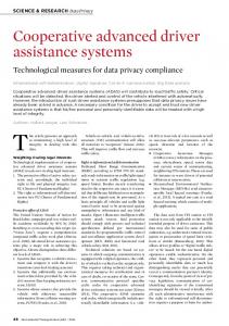
Fig. 2.
Petri Net model level 1: System context
This net corresponds to the formal representation of the system architecture in Fig. 1. On this level, all the interfaces are defined as uni-directional channels. C. Nets on the Process Level The next level is formed by the nets of process visualization. This level defines what scenarios can be passed in what sequence. In a central position are the transitions and places that provide additional application logics. To the right and to the left are two dark-grey boxes, which accommodate the interfaces to the outside. Messages sent to a receiver or received by a sender are combined in one place. At the train end the righthand box, and at the RBC end the left-hand box, is reserved for communications between train and control system.
A. Principles of the Net Structure
D. Scenario Nets
For ERTMS/ETCS modelling it was decided to visualize system context, sub-system process, operational processes in the form of scenarios and functions in an integrated manner. For this purpose, nets are decomposed to reflect these four aspects in four levels (see Table I).
The different scenarios are refined with two more aspects. The interfaces are disintegrated until individual messages are singled out. For each message there is a transition, referred to as driver, which is responsible for translating the message from the general data type ”message” into the required context
Fig. 5.
Fig. 3.
Petri Net model level 2: Process
specific type. In this context, messages are defined strictly in compliance with the definitions in chapters 7 and 8 of the System Requirements Specification [1]. In the nets themselves, the sequence of events is shown. The possibility of parallel event sequences as a function of specific initial situations and stimulations is given due consideration. Used as a basis here is SRS [1] and the related low-level documents.
Petri Net model level 4: Function
a box delimited by a dashed line; the inputs and outputs of the transitions of the higher-level net are outside this box. IV.
A. Model Complexity and Performance ERTMS/ETCS system modelling has to date proceeded to the degree of complexity given in Table II. As modelling aims at providing a detailed visualization of the air gap, the environment model only serves to produce stimulations, which is why the environment model was not taken beyond the required abstraction level. TABLE II.
Number of nets Net elements Places Transitions Hierarchy levels Lines of code (incl. comments)
Fig. 4.
Petri Net model level 3: Scenario
These nets comprise three areas: the application logics is again located in the centre, while the two boxes with the interfaces are located at the outer left and right. Next to the interfaces is a box designated radio driver and interface driver, respectively. All transitions in these boxes start with ’send’ or ’receive’; they comprise the receive or send logics for a specific message. This is why between these boxes and the application logics there are one or several more dark-grey boxes, providing one place for each individual message. The name of these boxes starts with ”messages”. This overall structure is common to all scenario nets. E. Functional Nets The functions, if explicitly modelled, form a net level of their own, and are visualized in the following way. The nets on this level are much simpler in structure: they only show the transition refinements. This is why they do not have any interfaces with external systems, even if the transition itself has such interfaces. Communication is safeguarded by the higher (scenario) level net. The net logics is accommodated in
R ESULTS
M ODEL COMPLEXITY Onboard 75 1,075 734 341 7 15,500
RBC 87 1,411 954 457 7 12,500
Environment 6 97 65 32 3 0
The model performance can be subdivided into two groups. On the one hand, modelling itself has achieved a number of aims: the SRS has been modelled in a formal way, the interface that has a central role to play for interoperability, i.e. the air gap between track and train, has been visualized, and the operational processes have been shown in the form of scenarios. A second group is represented by the simulation, which implies both simulation of the operational processes and simulation of the supervision functionality. One may compare the modeling approach chosen here, namely to use Petri nets, to one emplying state machines from the UML. Both share the idea of introducing hierarchy to offer views at different levels of detail. A main difference lies in the form in which the communication mechanism is represented. The Petri net model represents communications (or communication relations) explicitly in a graphical form via places and tokens. This is in particular helpful when communication is a major concern, as it is the case with the air gap. State machines would rather use events, i.e., non-graphical elements. This gives per se more readable results when entities partake in many activities. Here, this occurs at level 4. Our Petri net model employs “shared places” to remain readable. These are places like the one on the right in Fig. 5, which appear in more than one net.
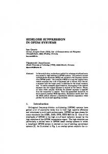
B. Quality Assurance of the Specification Validation of the model is, of course, an important aspect. The precise goal of the validation will depend on the purpose for which the model is to be used. Manual techniques like inspections or reviews [8], [9] common for program verification can be transferred to semi-formal and formal models. These manual techniques can be complemented by model animations and simulations, or by specific analyses. Some reachability analyses have already been done, in which individual scenarios and sequences of scenarios were used as examples. See Fig. 6 for an example visualisation of the results. Extended analyses will have to be the subject matter of future work. They can provide information on the possible sequences of execution of the model. V.
U SE OF THE P ETRI N ET MODEL
A. Safety Standards / Certification Support The formal model can assist in furnishing the proof of safety standards. Formal description of the system at the same time provides a clear and unequivocal definition of the system behaviour. On this basis system implementation can be tested with reference to the model, and the system behaviour can be checked for given conditions and also in an abstract manner, in the form of an analytical procedure.
3) Supporting hardware-in-the-loop tests: The approach sketched above is a way in which a single activity, namely test derivation, in standard development processes may be improved. There are more ambitious scenarios, in which test execution and the development itself might be modified. Thes require further extensions to the model. Presently, simulations of the model are made off-line, and timing is discrete in the form of discrete steps of sequences of events. Real-time simulations of models presuppose that in modelling the system, aspects of the real-time mode are given due consideration. I.e., the model needs a real-time interpretation, for which some additions to the model will be necessary. Also, a real-time compatible tool for simulating the model is needed. Adequate modelling and hardware provided, the simulatable model can support tests in the form of hardwarein-the-loop tests. For such tests, part of the real system is replaced by a simulation using suitable hardware, and one or several parts of the system are linked in the form of their implementation. This procedure allows hardware components to be tested individually. An overview about different simulations for validation and hardware-in-the-loop tests are given in the table III taken from [3]. “sim.” means here simulated. The bold numbers show the target system of the test. TABLE III.
B. Use for Test and Validation of Products In this respect, the model will serve as a reference for the behavior of the product. There are different forms of relation between model and product behavior. 1) Abstract observer: Each of the different levels of the Petri net can be viewed as an abstraction of the real system. A formal definition of the abstraction relation will map concrete traces to abstract ones (more generally, it may relate the trace sets). Then, any animation, simulation, test, or field observation of an implementation yields traces which can be checked for consistency with the model. This is a standard use case for any kind of model which has an operational semantics. On the other hand, such observations on an implementation may also be seen as a check for the correctness of the model. In system development, abstract specifications done in early design steps are often not correct in a strict interpretation of this term. For instance, they may be too restrictive (overspecification) or lack important detail (error handling, effects of low-level timing). Such discrepancies, if uncovered, can be used to correct or complete the model. Checking the observer relation is thus a means to arrive at a consistent development documentation. 2) Test construction: The scenario and functional nets provide (as indicated above) abstract view of the behavior of the implementation. These can obviously also be used as skeletons of test cases. To turn them into applicable test cases, the skeletons will have to be parameterized, translated to technical interfaces of the unit under test, and turned into executable scripts with stimuli specifications and pass/fail criteria. In other words, one may derive a test specification from the Petri net model by systematically covering the model.
onboard sim. real 1-2 0 0 1 1-n 0 0-n 1 0 1 2-n 0
trackside sim. real 1 0 1 0 0-m 1 0-2 1 0 2 0-m 1
S IMULATIONS AND T ESTS Aim Validation of oeprational procedures Test and validation of onboard subsystem Test and validation of trackside subsystem Validation of Interoperability trackside handover Stresstest
4) Interface Generators: A simulatable model can be used to supply the interfaces of a real or simulated system with stimulations. Possible approaches are presented in [7]. 5) Code Generation: Generally executable models can be transformed into software code. Analysed are the following three options of generating executable codes: 1) 2) 3)
Automatic source code generation, which is followed as a second step by conventional compilation. Compilation of the Petri net itself to produce an executable code. Execution of the net itself in the form of a system. Within the meaning of the definition of the term ’model’ this implies that the system is substituted by a model and its hardware. VI.
C ONCLUSION
On the basis of the System Requirements Specification and the relevant documents [1] an ERTMS/ETCS model was developed. This model visualizes the system in the form of three Petri net models. The onboard and trackside systems together form the core which is embedded in a model of the environment. The two core models reflect the aspects of the sub-system context, of the processes proceeding within
Fig. 6.
Occurence Graph of Transition Level 1 to Level 2/3
the sub-systems, of operational processes in the form of scenarios and specific functions. In developing these models, a combination of three elements was used: Petri nets as a means of description, an integrated method and the tool Design/CPN. It was demonstrated that during the phases of system development, covering the system specification through to the final system design, a model based on Petri nets can be used. R EFERENCES [1] [2] [3]
[4]
[5] [6] [7] [8]
[9]
UNISIG: ETCS Subset 026 - SRS. System Requirements Specification. UNISIG: TIU FFFIS. 97E117 Version 1.0. Meyer zu H¨orste, M.: Methodische Analyse und generische Modellierung von Eisenbahnleit- und -sicherungssystemen. Fortschritt-Berichte VDI. Series 12, No. 571, D¨usseldorf, 2004 (In German). GMA Unterausschuss 1.8.1 Standardisierte Beschreibungsmittel in der Automatisierungstechnik: Glossar. Braunschweig, 1998. www.ifra.ing.tubs.de/gma181/glossar.htm. K. Jensen: Coloured Petri Nets, Volume 1, Monographs in Theoretical Computer Science. Springer-Verlag, Berlin u.a. , 1992. Design/CPN: Occurrence Graph Analyser-Manual. Version 3.0, Aarhus, 1996. H.-M. Schulz: The complexity of technical testing. FORMS’98, Braunschweig, 1998. M. E. Fagan: Design and Code Inspections to Reduce Errors in Program Development. IBM Systems Journal, July 1976, pp 182–211, reprinted 1999, pp 258–287. E. Yourdon: Structured Walkthroughs. Prentice-Hall, Englewood Cliffs, NJ, 1979.