POLISH MARITIME RESEARCH 1(89) 2016 Vol. 23; pp. 31-36 10.1515/pomr-2016-0005
MODELLING THE DYNAMICS OF SHIPS WITH DIFFERENT PROPULSION SYSTEMS FOR CONTROL PURPOSE Witold Gierusz, Assoc. Prof. Gdynia Maritime University, Poland
ABSTRACT Two different propulsion systems are analyzed from point of view of future control applications. The traditional one consists of a pushing single screw propeller and a blade rudder. The other system is based on pod (pods): pulling or pushing ones. The equations describing forces and moments generated in both systems, are presented. Exemplary results of a simulation in comparison to the real-time experiments for two ships are also shown. Keywords: ship dynamics, simulation model, pod propulsion, conventional propulsion, tests results
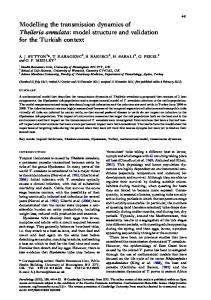
INTRODUCTION The simulation models of ship’s dynamics play an important role in synthesis process of control systems. For many years most ships were equipped with conventional propulsion system with a single screw and a blade rudder. The modelling of such system was properly performed and has rich bibliography. Nowadays a different propulsion system has become more and more popular. It is based either on azimuthing thrusters (e.g. ducted ones) or pods. Unfortunately, the way the systems work is somewhat different and each of them should be modelled separately. This article is an attempt to present distinct manners of computing the forces and moment produced by main propulsion systems, conventional one and modern, in simulation models of the ships’ dynamics. The ship floating on the water surface should be treated as a rigid body with 6 degrees of freedom (6 DOF) with 3 linear velocities and 3 angular ones. The movement of the ship can be analyzed in relation to the commonly used , two Cartesian dextrorotatory coordinate systems: the moving one fixed to the ship and the inertial one fixed to the Earth. The origin of the ship-fixed frame commonly coincides with the ship’s centre of gravity , see Fig.1.
where: m - mass of the ship, l x, Iy, Iz - moments of inertia around X-Y-Z axes, respectively, Xtot , Ytot , Ztot - total forces acting along appropriate axes, Ktot , Mtot , Ntot - total moments acting on the hull. For many control applications like the heading, speed and/or trajectory stabilization it is a common practice to neglect pitch, roll and heave motion with assuming that p = q = w = 0. Consequently, the 6 DOF model of the ship is converted to the 3 DOF model: m(u - rv) = Xtot [N] (7) m(v + ru) = Ytot [N] (8) Izr = Ntot [Nm] (9) The right hand sides of the above given equations represent forces and moments from different sources and have the form:
Ship dynamics can be described by means of strongly nonlinear dimensional equations based on Newton’s second law. m(u + qw-rv) = Xtot m(v + ru-pw) = Ytot m(w + pv-qu) = Ztot Ixp + (Iz- Iy)qr = Ktot Iyq + (Ix- Iz)rp = Mtot Izr + (Iy- Ix)pq = Ntot
(1) (2) (3) (4) (5) (6)
Fig.1. The Earth-fixed reference frame X0-Y0-Z0 and the ship-fixed reference frame X-Y-Z. The quantities u, v, w denote linear velocities and p, q, r angular ones.
POLISH MARITIME RESEARCH, No 1/2016 Unauthenticated Download Date | 5/16/16 8:26 AM
31
Xtot = X h + Xasd + Xpsd + Xdis Ytot = Y h + Yasd + Ypsd + Ydis Ntot = Nh + Nasd+ Npsd + Ndis
(10) (11) (12)
where the applied indices denote , respectively: h - hydrodynamic phenomena related to the hull movement through the water, asd - active steering devices like main propulsion or tunnel thrusters, psd - passive steering devices like blade rudder, dis - external disturbances like wind, waves etc. Based on the above presented equations the simulation model of the ship’s dynamics can be presented in a block form , Fig.2.
publications of MMG group for conventional hull shape and formulas for ships equipped with pods, presented in PhD thesis of Michael Woodward [16]). FORCES AND MOMENTS FROM MAIN PROPULSION SYSTEMS
One can consider two main cases; the traditional propulsion system consisted of a pushing single screw propeller powered by main engine , and a blade rudder, and another system based on pod (pods) propulsion, pulling or pushing one. The equations describing dynamics of both systems are shown below (The presented formulas for forces generated by main propulsion system are in general valid for ship moving with the almost constant speed (cruising speed) and the small angles between longitudinal ship axis and direction of the vessel motion, amounting no more than about ± 300. In the other case , e.g. during manoeuvres , the above mentioned equations are much more complicated.). THE SYSTEM OF SINGLE SCREW PROPELLER AND BLADE RUDDER
Fig.2. The block diagram of the ship dynamics model
THE FORCES AND MOMENTS ACTING ON THE HULL HYDRODYNAMIC FORCES AND MOMENTS
To estimate the properties of the floating vessel it is essential to determine the hydrodynamic forces and moments acting on the hull. Unfortunately, it is also the most difficult problem to solve due to the fact that the functions of ship motion parameters are complicated. There are several methods to calculate the above mentioned quantities. The most reliable seems to be a result of experimental scalemodel tests in towing tanks. But such way is expensive and time consuming. In recent years two other methods became commonly used. The first one, based on semi-empirical results , uses geometrical hull dimensions and load conditions. This method was proposed by Japanese research group named MMG, organized by the Manoeuvrability Sub-Committee of JTTC. The formulas useful for hydrodynamic forces calculation were published in [7], [8], [10]. The second solution is application of a numerical method based on advanced computer techniques named CFD (Computational Fluid Dynamics) [17]. Forces resulting from the water flowing around the hull during manoeuvres and the interaction phenomena between hull, propulsion devices and blade rudder can be estimated with increasing accuracy. The first method seems to be easier for practical implementations. When one considers the manoeuvring characteristics of the ships with different propulsion systems it should be noted that there are two ways to obtain formulas for hydrodynamic forces and moments (see the mentioned 32
The main task of the ship engine is to generate the proper longitudinal force Xprop for ahead or astern ship motion, given by formula: Xprop = (1-t)Tprop
(13a)
where: Tprop - propeller thrust t - thrust deduction factor. When the ship has a single propeller , one can introduce a small transverse force Yprop and rotating moment Nprop to take into account the lateral reaction of the screw propeller: Yprop = kprop Xprop Nprop= Yprop Lprop
(13b) (13c)
where: kprop - constant coefficient dependent on the particular propulsion system, Lprop - distance between the origin of body frame and the screw propeller. The commonly used equation for calculating the thrust is as follows [7]: (14)
where:
𝜚w - density of water,
ng - number of propeller revolutions, Dprop - screw propeller diameter, KT - non-dimensional thrust coefficient, J - advance coefficient.
POLISH MARITIME RESEARCH, No 1/2016 Unauthenticated Download Date | 5/16/16 8:26 AM
The thrust coefficient K T strongly depends on screw construction, its rotational speed and velocity of water flow around the screw propeller. This relationship is often presented graphically as follows:
The analysis of the rudder normal force Frud for different values and signs of speed, thrust and rudder angle was presented in [15]. One can assume, for simplification, that Frud ≠ 0 only for Tprop > 0, see Fig.4.
Fig.4. Two cases when the normal rudder force Frud is significantly different from zero Fig.3. Open water diagram for Wageningen B5-75 screw propeller. Exemplary relationship between the thrust coefficient KT , torque coefficient KQ , propeller efficiency η0 - versus the advance coefficient J [4]
According to the notation given beneath the equations (10) - (12) one can write: Xasd1 = Xprop , Yasd1 = Yprop , Nasd1 = Nprop Forces and moment from the blade rudder are complicated product of interaction between hull, screw propeller and rudder plate. Based on the results presented in [12] and [13] one can write the following equations: X rud = Frud sin(δef ) Yrud = (1 + aH)Frud cos(δef ) Nrud = lrud Yrud
(15) (16) (17)
where: Frud - rudder normal force, aH - rudder induction coefficient, δef - effective angle of rudder deflection, lrud - distance from rudder axis to the origin of body frame. The rudder normal force can be calculated from the following formula [15]:
More details can be found in [10], [12] and [15]. According to the notation given beneath the equations (10) - (12) one can also write for this case: Xpsd1 = X rud , Ypsd1 = Yrud , Npsd1 = Nrud POD (PODS) PROPULSION SYSTEM
The most important difference between the classic propulsion system and pod drive is the possibility of adjusting the pod angle in any position within the range (-180 ÷ +180) [deg] in relation to the longitudinal axis of the ship. Moreover, the water can flow toward the pod from any angle, especially during turning manoeuvres. There are a few publications devoted to modelling motion of the ships with pod propulsion, e.g. [2], [9], [11], [14]. Fortunately, the sailing of the ship with cruising speed involves deflection of the pod (pods) within the range similar to that of the blade rudder deflection , i.e. (-30 ÷ +30) [deg]. Therefore such mode of work is analyzed below. The main equation describing longitudinal and lateral forces resulting from pod propulsion in relation to water flow are as follows [1]: (19) (20)
(18)
where: Arud - rudder area, urud - average rudder inflow velocity, hrud - rudder vertical height, crud - rudder span. The most difficult problem related to the above given formula is proper calculation of the urud . The quantity depends (in a nonlinear manner) on ship speed and water flow direction [15].
where: npod - number of pod propeller revolutions, Dprop - diameter of the pod propeller, KTx(δrel, J), KTy(δrel, J), - non-dimensional thrust coefficients, δrel - pod angle of attack in relation to water flow direction. It should be emphasized that δrel is in general different in relation to the pod deflection angle δ , see Fig.5 for the case of the pulling screw propeller. The angle σ denotes the angle of the direction of the free water stream (big blue arrow) in relation to the ship longitudinal axis. POLISH MARITIME RESEARCH, No 1/2016
Unauthenticated Download Date | 5/16/16 8:26 AM
33
Xasd2 = Xpod , Yasd2 = Ypod ,Nasd2 = Npod Another important problem related to the pod propulsion system is estimation of the resistance forces generated by the pod construction , i.e. its strut, fin and nacelle - see Fig.7.
Fig.5. Definition of the relative pod angle of attack, δrel
The relationships between KTx(δrel, J) or KTy(δrel, J), and δrel are crucial in the modelling process [14]. The most reliable way to obtain them is to use open-water pod propulsion tests. Exemplary results for different advance coefficients are presented in Fig.6, [6]. Notice that KTy(δrel, J), for δrel = 0 is not equal to zero!
Fig.7. Definition of the longitudinal and lateral resistance forces generated by the pod construction. Big blue arrow denotes the direction of the free water stream
The formulas for the above mentioned forces in relation to the resultant water flow direction σ are as follows [16]: (24) (25)
Fig.6. The non-dimensional thrust coefficients KTx and KTy in relation to the relative pod angle of attack , δrel. The solid line was drawn for J = 0, dash-dotted line for J = 0.44 and dashed line for J = 0.71
The forces from the equations (19) and (20) are obtained in relation to the water stream direction (blue arrow in Fig. 5). More useful for modelling of the pod dynamics are forces calculated in relation to the ship axes: longitudinal and lateral one, respectively. Such forces and turning moment can be obtained from the following formulas: Xpod = Fxpod cos(σ) + Fypod cos(σ+π/2) Ypod = Fxpod sin(σ) + Fypod sin(σ+π/2) Npod = Ypod xpod + Xpod y pod
where: Sbp - transverse area of the strut and nacelle, Vrel - velocity of resultant water flow acting on the pod body, CTx, CTy - non-dimensional drag coefficients. The water stream with the speed Vrel hitting onto the strut and nacelle is a sum of two components: the first one is the free stream resulting from the whole ship motion and the second one being an effect of the pod screw rotation. More details one can find in the already mentioned Woodward’s PhD thesis. The reliable way for obtaining values of the non-dimensional drag coefficients CTx, CTy is to perform the open-water tests of the pod without screw propeller [6]. Exemplary diagrams with results of such open-water tests are presented in Fig.8.
(21) (22) (23)
where xpod and y pod denote coordinates of the rotation axis of the pod in relation to the origin of the ship body frame. According to the notation given beneath the equations (10) - (12) one can write: 34
Fig.8. The non-dimensional drag coefficients CTx and CTy versus the relative resultant angle of water flow, σ
POLISH MARITIME RESEARCH, No 1/2016 Unauthenticated Download Date | 5/16/16 8:26 AM
Both the forces Fxop and Fyop should be recalculated to forces Xop ,Yop and moment Nop in relation to the ship reference frame in the similar way as to propulsion forces. According to the notation given beneath the equations (10) - (12) one can also write for this case: Xpsd2 = Xop , Ypsd2 = Yop , Npsd2 = Nop Equations describing forces generated by other thrusters are commonly known and one can find them in e.g. [3].
THE CASE STUDY The equations presented in the previous section were applied to create simulation models of two ships. Both ships are used in the centre for training navigators run by the Foundation for Safety of Navigation and Environment Protection at the Silm lake near Ilawa , Poland. The ship named ‘’Blue Lady’’ is an isomorphous model of the VLCC tanker in 1:24 scale. Its dynamic model was described in detail in [5] and its side view is shown in Fig.9.
Fig.12. Trajectories of the real ship (solid line) and its model (dotted line) during turning manoeuvre with full ahead speed. Deflections of the blade rudder: δ = +350 on the left hand side and δ = -350 on the right hand side, respectively.
‘’Dorchester Lady’’
Fig.13. Trajectories of the real ship (solid line) and its model (dotted line) during turning manoeuvre with full ahead speed. Deflections of the blade rudder: δ = +150 on the left hand side and δ = -150 on the right hand side, respectively.
Fig.9. The side view of the model of the ship ‘’Blue Lady’’
The second ship named ‘’Dorchester Lady’’ is a model of the LNG tanker in 1:24 scale. Its side view is shown in Fig.10
Fig.14. Trajectories of the real ship (solid line) and its model (dotted line) during turning manoeuvre with full ahead speed. Deflections of the blade rudder: δ = +350 on the left hand side and δ = -350 on the right hand side, respectively. Notice the strong influence of the wind in the left hand side figure. Fig.10. The side view of the model of the ship ‘’Dorchester Lady’’
Exemplary results of the experiments with simulation models of the ships and real-time trials are presented in the next four figures (The experiments on the lake Silm began with different ship heading (e.g. Fig.14) therefore the simulation runs had to repeat the same conditions.).The reference speed was adjusted to ‘’Full-ahead’’ and deflections of the steering devices were set at two values: average one ±100 or ±150 and the large one ±350.
As one can see the fitting of the ‘’Dorchester Lady’’ simulation model is slightly worse than in the case of the ‘’Blue Lady’’. One of the reasons for this situation can be much bigger influence of the wind blowing during experiments on the lake. The LNG tanker is more sensitive to the external disturbance due to its larger topside projected area (see also Fig.10).
‘’Blue Lady’’
CONCLUSIONS
Fig.11. Trajectories of the real ship (solid line) and its model (dotted line) during turning manoeuvre with full ahead speed. Deflections of the blade rudder: δ = +100 on the left hand side and δ = -100 on the right hand side, respectively.
In the article the pod propulsion system was analysed in comparison to the conventional one in similar simple working conditions. The ship movement with cruising speed during turning manoeuvre with rather small deflections of the steering devices, was presented. It should be emphasized that the ship equipped with pods has totally different manoeuvring characteristics and poor course-keeping stability. Therefore control systems designed POLISH MARITIME RESEARCH, No 1/2016
Unauthenticated Download Date | 5/16/16 8:26 AM
35
for such ships have to be constructed in a different way than for the systems for conventional ships. The described models of driving devices can be used for speed, heading and/or trajectory stabilization but DSP systems or precise steering at small speeds should comply with equations describing hull-pod and pod-pod interactions. The proposed process for reviewing the ship’s control system is an indirect method of verification which is placed between the low-cost methods of conducting research using computer simulations and tests with the use of expensive full-size ships. The potential results obtained by using the large- scale model may be considerably closer to the phenomena occurring in reality than the results that may be obtained through computer simulations. But simulation runs performed with proper and accurate computational models of the ship dynamics are an important step which enables to avoid many mistakes in control systems before they are tested in real-time experiments. The article presents only the main equations described forces and moments acting on the ship’s hull. More details can be found in the literature referred to, below.
9. Kanar J., The Semi-empirical Method for Prediction of the Driving Characteristics of the Ships with Multi-podded Propulsion (in Polish), PhD Thesis, Gdansk University of Technology, Poland, 2009.
BIBLIOGRAPHY
14. Reichel M., The Prediction of the Manoeuvring Characteristics of the Ships with Azimuthing Propulsion (in Polish), PhD Thesis, Gdansk University of Technology, Poland, 2011.
1. Ankudinov V., Kobylinski L. K., Review of Ability to Simulate Azimuthing Device Interactions, AZIPILOT 2., Deliverable 2.3., Public.pdf, www.transport-research.info, 2012. 2. Brandner P. Renilson M. Interaction Between Two Closely Spaced Azimuthing Thrusters, Journal of Ship Research, v.42, 1998. 3. Brix J. (Ed.), Manoeuvring Technical Manual, Seehafen Verlag GmbH, Hamburg, 1993. 4. Carlton J. Marine Propellers and Propulsion, Butterworth and Heinemann, Burlington, 2007. 5. Gierusz W., Simulation model of the ship-handling training boat ,,Blue Lady’’, Int. IFAC Conference Control Applications in Marine Systems CAMS’01, Glasgow, Scotland, 2001.
10. Kose K., On a New Mathematical model of Manoeuvring Motions of a Ship and Its Applications, International Shipbuilding Progress, 1982. 11. Mello Petey de F., Advanced Podded Drive Simulation for Marine Training and Research, International Marine Safety Forum Meeting, Warnemuende, Germany, 2008. 12. Molland A.F. ,Turnock S.R., Prediction of Ship- RudderPropeller Interaction at Low speeds and in Four Quadrants of Operation, Int. IFAC Conference on Manoeuvring and Control of Marine Craft MCMC’94, Southampton, UK, 1994. 13. Ogawa A. , Kasai H, On the Mathematical Model of Manoeuvring Motion of Ships, International Shipbuilding Progress, 1978.
15. Shouji K., Ishiguro T. , Mizoguchi S., Hydrodynamic Forces by Propeller and Rudder Interaction at Low Speed, Int. IFAC Conference MARSIM and ICSM, Tokyo, Japan, 1990. 16. Woodward M., Control and Response of Pod Driven Ships, PhD Thesis, University of Newcastle-upon-Tyne, 2005. 17. The Manoeuvring Committee. Final Report and Recommendations to the 23rd ITTC, Proc. of the 23rd International Towing Tank Conference, Venice, Italy, 2002.
CONTACT WITH THE AUTHOR
6. Grygorowicz M., Hydrodynamics Characteristics of the Isolated Pod Model for Two-pods Propulsion System (in Polish), Report WOiO 3/03/BZ, Gdansk University of Technology, 2003. 7. Inoue S. , Hirano M. , Kijima K., Hydrodynamic Derivatives on Ship Manoeuvring, International Shipbuilding Progress, 1981. 8. Inoue S., Hirano M.,Kijima K. ,Takashina J., Practical Calculation Method of Ship Manoeuvering Motion, International Shipbuilding Progress, 1981. 36
POLISH MARITIME RESEARCH, No 1/2016 Unauthenticated Download Date | 5/16/16 8:26 AM
Witold Gierusz Gdynia Maritime University 83 Morska St. 81-225 Gdynia Poland e-mail:
[email protected]