PHYSICS OF PLASMAS 23, 057101 (2016)
Models, assumptions, and experimental tests of flows near boundaries in magnetized plasmas M. Umair Siddiqui,1,a),b) Derek S. Thompson,1 Cory D. Jackson,2 Justin F. Kim,2 Noah Hershkowitz,2 and Earl E. Scime1 1 2
Department of Physics and Astronomy, West Virginia University, Morgantown, West Virginia 26506, USA Department of Engineering Physics, The University of Wisconsin-Madison, Madison, Wisconsin 53706, USA
(Received 10 November 2015; accepted 21 January 2016; published online 10 March 2016) We present the first measurements of ion flows in three dimensions (3Ds) using laser-induced fluorescence in the plasma boundary region. Measurements are performed upstream from a grounded stainless steel limiter plate at various angles (w ¼ 16" to 80" ) to the background magnetic field in two argon helicon experiments (MARIA at the University of Wisconsin-Madison and HELIX at West Virginia University). The Chodura magnetic presheath model for collisionless plasmas [R. Chodura, Phys. Fluids 25, 1628 (1982)] is shown to be inaccurate for systems with sufficient ion-neutral collisions and ionization such as tokamak scrape off layers. A 3D ion fluid model that accounts for ionization and charge-exchange collisions is found to accurately describe the measured ion flows in regions where the ion flux tubes do not intersect the boundary. Ion acceleration ~# B ~ direction is observed within a few ion Larmor radii of the grounded plate for in the E w ¼ 80" . We argue that fully 3D ion and neutral acceleration in the plasma boundary are uniquely caused by the long-range presheath electric fields, and that models that omit presheath effects C 2016 under-predict observed wall erosion in tokamak divertors and Hall thruster channel walls. V AIP Publishing LLC. [http://dx.doi.org/10.1063/1.4943523] I. INTRODUCTION
The plasma boundary region with obliquely incident magnetic fields has been a subject of considerable interest since Chodura’s seminal work.1 The topic has direct relevance to a number of important plasma physics applications, such as first wall interactions in fusion experiments and Hall thrusters. While plasma boundaries in unmagnetized and weakly collisional plasmas have been investigated through theory,2,3 computer simulations, and experiments,4–6 tests of models concerning plasma boundary regions with magnetic fields oblique to the absorbing surface has been difficult to perform. In this work, we present the first fully three dimensional (3D) measurements of ion flows near an absorbing surface oriented at various angles to the background magnetic field. We argue that complete understanding of the system and accurate predictions of wall particle fluxes and erosion rates requires a kinetic analysis. Also, we show that the long-range presheath electric fields generate sputtering particle fluxes at various angles of incidence to the boundary that are not included in simpler sheath models. In this paper, we review salient results of experiments in 2D, which motivated recent 3D measurements of ion flows near the boundaries of magnetized plasmas. The new results are then discussed with respect to their implications on wall loading and sputtering of plasma first wall materials. In Secs. I A and I B, we present some background information on the “magnetic presheath” and its relevance to Note: Paper TI2 3, Bull. Am. Phys. Soc. 60, 303 (2015). a) Invited speaker. b) Present address: Phase Four, Inc., 133 Center St. Unit A. El Segundo CA, 90245. Electronic mail:
[email protected] 1070-664X/2016/23(5)/057101/14/$30.00
important plasma physics applications. The experimental setups and diagnostics are described in Section II. We discuss the previous 2D measurements in Section III A and the new 3D measurements in Section III D. A. Brief history of the “magnetic presheath”
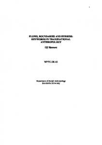
The canonical work on the plasma boundary with obliquely incident magnetic fields was produced by Chodura.1 Chodura performed a particle-in-cell (PIC) simulation of ions and electrons in the presence of a background magnetic field at an angle w to the x-axis of the Cartesian coordinate space, as shown in Figure 1. The x-axis was normal to an absorbing
FIG. 1. Chodura picture of the plasma boundary with oblique magnetic fields.
23, 057101-1
C 2016 AIP Publishing LLC V
Reuse of AIP Publishing content is subject to the terms at: https://publishing.aip.org/authors/rights-and-permissions. Downloaded to IP: 157.182.27.154 On: Thu, 10 Mar 2016 18:57:01
057101-2
Siddiqui et al.
Phys. Plasmas 23, 057101 (2016)
boundary. Particles entered the simulation at x ¼ 0 with a drift velocity vxo and exited the domain at x ¼ L. Neither collisions nor ionization were included. The simulation showed that stable equilibria were found only when the ions flowed into the simulation space with a velocity greater than the sound speed along the magnetic field line, vxo " cs cosðwÞ (the drift velocity along thep magnetic ffiffiffiffiffiffiffiffiffiffiffiffi field line was at least the sound speed), where cs ¼ Te =mi is the ion acoustic speed for Te % Ti ; Te;i is the electron/ion temperature, and mi is the ion mass. Chodura also found that ions exited the domain at x ¼ L at the sound speed along the x-axis and that plasma everywhere in the simulation space maintained quasineutrality. Using fluid model scaling arguments, he claimed that the length of this acceleration region, kmps, was given by kmps ¼
pffiffiffi cs 6 sinðwÞ; xci
(1)
where xci ¼ eB=mi is the ion cyclotron frequency.1 Chodura postulated that the plasma boundary region in the presence of obliquely incident magnetic fields is divided into three subsections near the absorbing surface: the “collisional presheath,” where ions are accelerated in a quasineutral plasma to the sound speed along the field line over a distance that scales with the ion collision length, k (k ¼ 1=nn r, where nn is the neutral density and r is the collision cross section); the “magnetic presheath,” where ions are accelerated in a quasineutral plasma to the sound speed normal to the surface over a distance kmps; and the sheath, a non-neutral region where ions fall towards the wall over a few electron Debye lengths, kD. For these arguments, kD & kmps & k. The Chodura model is now the standard paradigm of the plasma boundary with oblique magnetic fields and is presented in two textbooks.7,8 The vxo " cs cosðwÞ requirement has even been described as the “Bohm–Chodura” criterion.9 However, subsequent investigations of the magnetic presheath showed that the canonical model fails to recreate several important features of the magnetized plasma boundary. Riemann presented fully 3D fluid models of the collisional and magnetic presheaths, including the effects of ion-neutral ~' B ~ direccollisions, and found that ion fluid drifts in the E tion are comparable to cs.10 These 3D flows were later predicted by Stangeby9 and Ahedo.11,12 Ahedo also showed that when k=kmps ( 1, the collisional and magnetic presheaths merge “into a single quasineutral region, affected by both ~ ' B] ~ effects.”11 collisional and B-drift [E 13 Daube et al. argued that fluid models of the magnetic presheath break down when ion flux tubes intersect the wall and that kinetic theories are necessary for predicting ion distribution functions at the sheath edge. In this region, the ion orbits intersect the boundary but the electron orbits remain closed. Tskhakaya and Kuhn14 and Khaziev and Curreli15 have since modeled multi-dimensional ion velocity distribution functions (IVDFs) at the sheath edge with obliquely incident magnetic field using PIC simulations demonstrating fully 3D particle flows. There have been only three experimental investigations of the plasma boundary with obliquely incident magnetic fields. Kim et al.16 and later Singha et al.17 measured electric
potential structures in front of a negatively biased plate with obliquely incident magnetic fields in a low temperature argon plasma. They were unable to measure ion drift velocities and thus could not validate the Chodura magnetic presheath model. Both works investigated weakly collisional magnetic presheaths, where k=kmps " 10. They found regions of disd logð/Þ, where / is the local electric potential and x is tinct dx the distance from the biased plate. The length of one of the regions was proportional to the Chodura prediction for kmps over a variety of experimental conditions.16,17 Because ion flows were not measured, it is unclear if the electric potential structures corresponded to Chodura’s predictions. Siddiqui et al.18 measured 2D ion flows to a grounded plate with an obliquely incident magnetic field in the plane of the electric ~ B ~ plane) using laser-induced and magnetic fields (the Ejj fluorescence (LIF). The measurements were performed in a helicon discharge at different neutral pressures such that k=kmps ¼ 0:5 to 4. These 2D ion flow measurements motivated our recent 3D ion flow measurements in the magnetic presheath. Both the 2D and recent 3D LIF measurements are the focus of this paper. B. Importance of magnetic presheath physics 1. Tokamak wall loading
Understanding the magnetized plasma boundary is critical for mitigating deleterious effects in a number of important plasma applications. Tokamak first wall surfaces, such as divertor and limiter plates, are intersected by the background magnetic fields at large angles of incidence (w " 80) ). The predicted particle heat fluxes for the next generation of tokamaks, such as the National Spherical Torus ExperimentUpgrade (NSTX-U), exceed the melting threshold for divertor materials19 prompting the use of novel first wall surfaces and “snowflake” magnetic geometries.20 Even with these creative solutions, wall particle fluxes generate significant impurities that detrimentally affect fusing plasma efficiency and particle transport.21,22 The sputtering rate of typical tokamak first wall materials is known to be non-linearly dependent on the impacting particle mass, velocity, and angle of incidence.23 Understanding the physics of 3D ion and neutral distribution function evolution near absorbing surfaces with obliquely incident magnetic fields is critical for predictive modeling of sputtering, recycling, and erosion rates of fusion experiment divertor materials in both normal and snowflake magnetic geometries. 2. Tokamak fluid model boundary conditions
Many models exist that investigate plasma flows in tokamaks. The velocity boundary conditions for ideal MHD codes are often given by null-flow or no slip conditions at the plasma-wall interface. The consequences of these boundary conditions are a topic of on-going discussion.24 Twofluid scrape off layer turbulence models have started to account for detailed magnetic presheath physics including ~' B ~ and gradient drift effects.25 The electric fields that E drive ions towards the absorbing boundaries are generated by electron pressure gradients along and perpendicular to the background magnetic fields. These fields arise through the
Reuse of AIP Publishing content is subject to the terms at: https://publishing.aip.org/authors/rights-and-permissions. Downloaded to IP: 157.182.27.154 On: Thu, 10 Mar 2016 18:57:01
057101-3
Siddiqui et al.
rpe term in non-ideal MHD equations. Experimental investigation of the plasma boundary with oblique magnetic fields is necessary to check theories of self-consistent electric field formation, and thus ion exit velocity conditions, in tokamakrelevant plasmas. 3. Hall thruster channel erosion
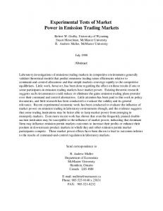
Hall thrusters are efficient plasma propulsion engines used for station-keeping on many manmade satellites and are candidate engines for the next generation of deep space science and exploration missions. Similar to experimental fusion reactors, a major limiting factor for Hall thruster operational lifetimes is the rate of erosion of the ionacceleration channel walls due to ion bombardment. Testing of Hall thruster prototypes is performed in the laboratory and via predictive computer codes of thruster wall erosion. HPHall, a popular hybrid PIC-ion fluid-electron code, predicts steady state potential and density profiles and ion impact velocities to the walls of common Hall thrusters.26,27 The code estimates wall sputtering rates using estimates for sputtering yields. Frequently, these models under-predict experimentally observed erosion rates. The ion acceleration channels contain largely radial magnetic fields to confine the ~! B ~ drifts. The magnetic fields intersect the electrons by E thruster channel walls at oblique angles. Figure 2 shows HPHall-predicted erosion of an SPT-100 Hall thruster after 840 h of run time presented by GameroCasta~ no and Katz28 in Figure 2. The red horizontal outlines at radial positions of 0.035 and 0.05 m, extending from an axial position of 0 to 0.025 m, represent the locations of the
Phys. Plasmas 23, 057101 (2016)
thruster acceleration channel walls. The semicircular region in the right hand sides of the panels represents the plasma plume expansion into free space. The exit aperture of the thruster is located at an axial position of 0.025 m. Panels (a), (b), and (c) show color plots of the plasma density [m"3], electric potential [V], and electron temperature [eV] in the thruster channel. Panels (d), (e), and (f) show the same parameters after 840 h of thruster run time as predicted by HPHall. The predicted erosion of the channel walls is evidenced by the recessed locations of the red wall outlines in panels (d), (e), and (f), especially at axial positions near 0.02 m. The black lines in panels (b) and (e) show stream lines of the magnetic fields in the system. The magnetic fields are on the order of 100 G, and the propellant is xenon. Xenon is ionized at low axial positions and accelerated by the axial electric field near the exit aperture. The acceleration of the ions produces net thrust. Figure 3 compares the wall erosion prediction from Figure 2 to an experimental 1000 h wall erosion test.28 The pink and black lines show the location of the upper channel wall of the Hall thruster in the simulation and experiments, respectively. The different symbols represent different times in the tests. HPHall accurately predicts experimentally observed wall erosion rates near the thruster exit aperture at an axial position of 0.025 m. However, the model significantly underpredicts the observed erosion upstream in the thruster channel around an axial position of 0.02 m in Figure 3. The discrepancy may be caused by the common assumption that the ions are unmagnetized everywhere in the sys~! B ~ direction tem. HPHall neglects the ion motion in the E
FIG. 2. HPHall wall erosion test results of an SPT-100 Hall thruster, with permission from Gamero-Casta~ no and Katz.28 Panels (a)–(c) show the simulation space setup, and panels (d)–(f) show the simulation space and the predicted recession of the thruster channel walls after 840 h of thruster run time.
Reuse of AIP Publishing content is subject to the terms at: https://publishing.aip.org/authors/rights-and-permissions. Downloaded to IP: 157.182.27.154 On: Thu, 10 Mar 2016 18:57:01
057101-4
Siddiqui et al.
Phys. Plasmas 23, 057101 (2016) TABLE I. Comparison between typical helicon discharge parameters and detached divertor scrape off layer parameters from DIII-D33 and an upstream region of a high power BHT-600 Hall thruster.30
FIG. 3. A comparison of HPHall wall erosion test results of an SPT-100 Hall thruster from Figure 2 to experimental results, with permission from Gamero-Casta~no and Katz.28
during the particle push stage of the ion PIC code.29 In the upstream region, the ions have low energy as they have not yet been accelerated by the axial electric field around the exit aperture, and the magnetic fields are obliquely incident to the walls. As with tokamak first wall sputtering, the sputtering yields of typical thruster wall materials (typically alumina or boron nitride) are highly dependent on the impacting species energy and angle of incidence.30 In this paper, we show that the under-predicted wall erosion in the upstream regions of Hall thrusters may be due to unaccounted magnetized 3D acceleration of ions near the wall, especially in the ~! B ~ direction. E II. EXPERIMENTAL SETUP
In this work, we present ion flow measurements to a grounded stainless steel limiter plate held at varying angles relative to the background magnetic fields in argon helicon discharges to check models of the plasma boundary with obliquely incident magnetic fields under plasma conditions relevant to the applications noted in Secs. I A and I B. The initial measurements were performed in the Magnetized AnisotRopic Ion distribution Apparatus (MARIA) at the University of Wisconsin-Madison, which motivated further measurements in the Hot hELIcon eXperiment (HELIX) at West Virginia University. A. Helicon apparatus
Helicon discharges are plasmas maintained by resonant interaction of a bounded radio-frequency (RF) whistler wave and other coupled modes with the ionized gas. Recent reviews on helicon plasmas are given by Scime et al.31 and Chen.32 Helicon plasmas are ideal for studying technologically relevant boundaries in magnetized plasmas, as they contain background magnetic fields and generate plasma densities and temperatures comparable to the boundary regions of tokamaks and high power Hall thrusters. Table I
Plasma parameter
DIII-D detached SOL33
BHT-600 Hall thruster30
Helicon plasma
no (m#3) nn (m#3) Te (eV) Ti (eV) B (kG) kD (m) k (m) qi (m)
1019 # 1020 1018 # 1020 1–20 %Te 1–10 &10#5 &0.005