Poster Session
Modification of Surface of Polymeric Materials under Plasma-Beam Imitations of Flight in the Ionosphere1 V.N. Chernik, Yu.I. Tarasov, G.G. Bondarenko*, and A.I. Gaydar* D.V. Skobeltsyn Scientific Research Institute of Nuclear Physics of M.V. Lomonosov Moscow State University, 1, Leninskie gory, build. 2, Moscow, 119992, Russia, E-mail:
[email protected] *Research Institute of Advanced Materials and Technologies of MSIEM/TU 12, Malaya Pionerskaya str., Moscow, 115054, Russia, E-mail:
[email protected] Abstract – Oxygen plasma beam facility is considered to simulative test of spacecraft polymers. The plasma source is a magnetoplasmadynamic accelerator, adopted to oxygen gas operation by means of a double plasma contraction to reduce a contamination of the oxygen plasma beam. The Cu contamination content (3.6 ⋅ 10–6) is measured by X-ray microanalysis of deposition probe technique. Plasma beam exposed films of polyethylene, polymethyl methacrylate, polyimide were observed by a scanning electron microscopy. It is shown the heterogeneous etching forms the surface topology constituted cone or column-like protuberances, directed towards the beam. As in space the topology formed under the plasma beam is socalled carpet-like structure 1. Introduction Flight of a spacecraft in an ionosphere is accompanied by modification of surface of constructional polymeric materials under influence of environmental condition. One of the principal damaging factors of space in low Earth orbits (LEO) is the incident flow of atomic oxygen (АO). The flow is forming in an atmosphere of the Earth during photo-dissociation of oxygen molecules by ultraviolet radiation of the Sun. The AO high energy of 5 eV and chemical activity led to the rapid destruction of the materials. Since polymer-based materials are widely used on spacecrafts and most of them are susceptible to AO attack, their resistance to AO attack is of major importance in prolonged exposures of materials on the outside surfaces of spacecraft. Sources of molecular, plasma and ion beams are used for the accelerated ground-based tests of perspective materials of spacecraft. The long-term LEO flight simulation requires irradiation of materials with AO high fluence up to 1022–1023 cm–2. Simulator beam intensities do not exceed 1017 cm–2 s–1 (usually 1015– 1016 cm–2 ⋅ s–1) at 5 eV that results in practically unacceptable test duration [1]. The reduction of test duration is achieved by the increase of the particles beam energy within the limits of conservation of the interaction mechanism with the test material. _____________ 1
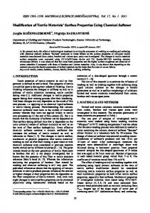
For this purpose in the work application of oxygen plasma beam from the plasma accelerator of a duoplasmatron type containing both atomic and molecular particles is described. The particles have been accelerated up to average speed of 13–16 km/s. Influence of such beam on materials leads to more intensive destruction of polymers than in natural conditions. 2. Experimental technique In our work, the accelerated simulative materials tests were carried out in oxygen plasma beams with average energy of oxygen atomic particles of 20 eV, formed by the plasma accelerator [2]. The plasma source is a magnetoplasmadynamic accelerator (MPDA) type, adopted to oxygen gas operation. A double plasma contraction is applied like in duoplasmatron to reduce a contamination of the oxygen plasma beam by electrode erosion emission [3]. During formation of a beam the special attention was given to decrease a concentration of both gaseous and electrode material impurities in it. The plasma jet contamination problem being minor for thruster is important for material test source. The cathode erosion products and inert gas are the impurities of the oxygen plasma Jet of the MPDA. The electrode material atoms are transported by plasma jet to an irradiated surface, are deposited and disturbed its behaviors. The inert gas is pumped poorly by some type of oil-free vacuum pumps as sputter-ion ones. To reduce the impurities yield to the plasma stream we employed magnetic andgeometric arc contraction by ferromagnetic intermediate electrode (IE) as in the duoplasmatron. The contraction creates potential barriers limiting cathode plasma ions (cum contaminants) moving towards the anode plasma in which the jet is formed. For the more complete decrease of the neutral impurities yield to the anode plasma, the IE hollow is pumped complementary. The pumping reduces pressure in the IE and maintains in the IE channel gas flow which is contrary the electrons. It hinders the diffusion of neutral particles Thus, contamination of the plasma jet by the ionized and neutral impurities from the cathode decreases. We can see this effect in Fig. 1.
The work is executed at support of the Russian Foundation for Basic Research (Grant No. 07-08-13656).
305
Modification of Material Properties
It shows the relative contents of the cathode gas xenon in the beam as function of the pressure in the intermediate electrode, or, in other words, of the pumping-off speed. As seen, at sufficient pumping-off rate the xenon yield sharply drops below sensitivity limit of 10–4. In Fig. 2, the mass spectrum of ions is shown. 8.5
10
Xe/O + O2, %
8 Xe0k
6
Xe10i 4
3. Result and discussion
2 0.043
0
0 0.42
This fact allows executing tests in the accelerated time scale by a method of EF using the witness polyimide film mass loss. The EF is not an absolute measure of AO projectiles arriving at the surface but it is the calculation of a fluence of a fictitious 5 eV AO beam that would initiate the same polyimide mass loss as observed in the facility. The EF is used as a means of comparison LEO AO impact with simulative ground based effect when AO energy may differ from 5 eV. The EF was calculated in an assumption of the polyimide erosion yield Y = 4.4 ⋅ 10–24 g/atom O under LEO impact.
2
4
ρk, pi
6
8 10 9.656363
Pressure, Pa Fig. 1. IE pressure dependence of Xe yield as discharge off (on the left), discharge current 10 A (on the right)
To evaluate the material surface contamination we use deposition probe technique as the sample played a part of the probe. For the analysis, we selected the polyvinyl thrimethyl silane (PVTMS) owing to its low AO erosion. We applied X-ray microanalysis (XMA) on scanning electron microscopy (SEM) basis to the sample exposed at the plasma beam with AO effective fluence of 1.4 ⋅ 1021 cm–1. The analysis results are shown in the Table.
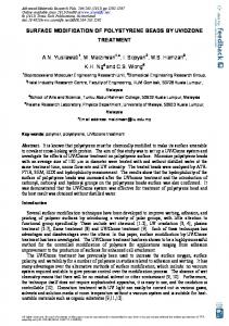
It contains, mainly, atomic and molecular oxyO exgen with a dissociation Table. Elemental composition of the PVTMS surface 21 –2 degree of 85 percents. Ar- posed at oxygen plasma beam with AO EF of 1.4 ⋅ 10 cm gon has arisen as an impuUnn. concen., Norm. concen., Element A# Error rity in the oxygen feed at % at % tank of the accelerator. Carbon 6 18.1 28.8 2.3 Xenon that feeds the holFluorine 9 12.5 12.6 2.0 low cathode, and other Aluminium 13 10.5 7.4 0.5 contaminants are not found at a sensitivity limit of Silicon 14 34.9 23.8 1.3 10–4. As the contaminants + Copper 29 1.7 0.5 0.1 O2 were not found out by Oxygen 8 22.3 26.7 2.8 mass-spectrometry, we have Total 90.6 100.00 employed an impurity deAr+ position probe technique. We observed a Cu line on the spectrum of exposed The beam impurity Fig.2. Mass spectrum of –6 sample which was not on the initial one. Deep profile level 3.5 ⋅ 10 metals ions in the plasma beam of X-ray emission shown the mean thickness of ob(from Fe to Cu) atoms per O atom is measured by deposition probe with post served layer was 1 micron approximately. On basis of exposition Rutherford back scattering analysis [3]. the findings we calculated Cu contamination in the layer composed approximately a Thus in the experiments it has been achieved the plasma beam. The –4 –2 mass of 1.5 ⋅ 10 g cm . As molecular mass of monolowering of concentration of metal impurity in a beam –6 mer C H Si is 100 a.u.m. or 1.7 ⋅ 10–22 g, that the 5 12 to a level below 3.5 ⋅ 10 atoms/oxygen ion and for 18 –2 xenon atoms below a limit of detection of mass- number of observed molecule is 10 mol ⋅ cm . The 16 spectrometers of 0.4%. It was possible due to double Cu portion is 0.5% or 0.5 ⋅ 10 atoms. Assuming contraction of discharge and the organization of a back 100% Cu atoms sticking to surface the Cu content is 16 21 –6 current of gas in an intermediate electrode channel 0.5 ⋅ 10 /1.4 ⋅ 10 = 3.6 ⋅ 10 Cu atom / О atom. Hence by introduction of additional evacuation of impurities. the oxygen plasma beam yields the contamination The plasma beam diagnostics is accomplished by monolayer under relatively high AO of 1.4 ⋅ 1021 cm–2. plasma electric probe, electrostatic energy analyzer, A SEM image of PVMTS is shown in Fig. 3. monopolar mass-spectrometer. Neutrals are evaluated As seen a branch of braids are formed under AO by means of bolometer / torsion balance device. impact. A depth of cavities between them is much smaller To evaluate the erosion yield we followed the than that one. The structure is shallow and directed standard technique of an AO effective fluence (EF) along the surface. That topology type is appeared calculation in ground-based facilities [4]. owing to low erosion yield of the silicone. 306 +
Poster Session
relief is grown, formed by buried regions and profile peaks. The topology form is characteristic for each polymer type. The surface topology of PE, PMMA, PI constitute cone or column-like protuberances, directed towards the beam.
Fig. 3. SEM image of PVMTS exposed in oxygen plasma beam with AO EF of 1.4 ⋅ 1021 cm–2. The visible margin of 50 microns
SEM images of polyethylene (PE), polymethyl methacrylate (PMMA), polyimide (PI) are shown in Figs. 4 and 5. Fig. 5. SEM image of PI exposed in oxygen plasma beam with AO EF of 0.5 ⋅ 1021 cm–2. The visible margin of 10 microns
Their heights exceed their diameters in many times. It is a result of the high-speed ratio of oxygen particles in the beam, leading to the anisotropic etching. Comparison of plasma-beam imitation with flight data has shown conformity for structure of polymeric materials tested. As in space the topology formed under the plasma beam is so-called carpet-like structure [5]. The peak forms differ drastically from PVMTS and display a variety of polymer bulk structures. References
Fig. 4. SEM image of PE (on top) and PMMA (below) exposed in oxygen plasma beam with AO EF of 0.5 ⋅ 1021 cm–2. The visible margin of 50 microns
Under oxygen plasma beam, the polymer surfaces are undergone heterogeneous destruction. The micro-
[1] J. Kleiman, Z. Iskanderova, Y. Gudimenko, and S. Horodetsky, in Proc. 9th Int. Symp. on Materials in Space Environments, 2003, pp. 313–324. [2] L.S. Novikov, V.N. Chernik, S.F. Naumov, S.P. Sokolova, T.I. Gerasimova, A.O. Kurilyonok, and T.N. Smirnova, J. of Spacecraft and Rockets 43/3, 534–537 (2006). [3] V.N. Chernik, in Proc. 7th Int. Symp. On Materials in Space Environment, 1997, pp. 237–241. [4] ASTM. Standard Practices for Ground Laboratory Atomic Oxygen Interaction Evaluation of Material for Space Applications. Designation E 2089-00, June 2000. [5] B.A. Banks, S.K. Miller, and Kim K. de Groh, Low Earth Orbital Atomic Oxygen Interactions with Materials NASA/TM-2004-213223 04, AIAA– 2004–5638, Glenn Research Center, Cleveland, Ohio.
307