CITATION: Usman, M. J., Xing, Z., Chiroma, H., Gital, A. Y. U., Abubakar, A. I., Usman, A. M., & Herawan, T. (2014). Modified Low Energy Adaptive Clustering Hierarchy Protocol for Efficient Energy Consumption in Wireless Sensor Networks. International Review on Computers and Software (IRECOS), 9(11), 1904-1915.
Modified Low-Energy Adaptive Clustering Hierarchy Protocol for Efficient Energy Consumption in Wireless Sensor Networks for Healthcare Applications Mohammed Joda Usman1, Zhang Xing1, Haruna Chiroma2a*, Tutut Herawan3 1 School of Electronics and Information Engineering, Liaoning University of Technology, Jinzhou 121001, China 2* Department of Artificial Intelligence 3 Department of Information System University of Malaya, Kuala Lumpur, Malaysia a Department of Computer Science Federal College of Education (Technical) Gombe, Nigeria
[email protected],
[email protected],
[email protected],
[email protected], *
Corresponding Author: Haruna Chiroma, Department of Artificial Intelligence, University of Malaya, Kuala Lumpur, Malaysia. +60143873685.
Abstract: In healthcare system, the sensor nodes are usually deployed in an unattended field or environment and replacement of batteries is very difficult if not impossible. In this paper, LowEnergy Adaptive Clustering Hierarchy (LEACH) protocol was modified (MoLEACH) to improve energy efficiency of the LEACH for healthcare applications. In cluster head selection, the MoLEACH consider the residual energy of each node for calculation of the threshold value for the next round, unlike the original LEACH that uses the residual energy of the network. Comparative simulation analysis between the MoLEACH and LEACH in testing different parameters such as first node dead, half node dead, the effect of the number of nodes to the network lifetime, and energy distribution was performed. The simulation results show that the number of nodes affects the network lifetime in which increments of number of nodes decrease the network lifetime. In small area, minimum number of nodes is better for network lifetime in both MoLEACH and LEACH protocols. The MoLEACH shows improvement of energy efficiency over the LEACH in energy distribution. The MoLEACH was found to improve the energy efficiency of the LEACH, hence, prolong the network lifetime, thus achieved high residual battery capacity. The MoLEACH proposed in this study can be used effectively in healthcare applications, thereby reduces the need for frequent recharging or replacement of batteries. The MoLEACH is an alternative to the LEACH in healthcare application systems such as in in-home monitoring, in-hospital monitoring, ambulatory monitoring, vital sign monitoring in-hospitals, monitoring elderly people at home care, monitoring in mass-casualty disasters and clinical monitoring for automatic patient monitoring without disturbing patient comfort by the need for frequent recharging or replacement of batteries.
Keywords: Wireless Sensor Networks; LEACH Protocol; Healthcare; Cluster-Based Routing; Energy Efficiency; Low-Energy Adaptive Clustering Hierarchy
1. Introduction Recently, a new class of network called Wireless Sensor Networks (WSNs) [1-2] emerged. The aim of this technology is to provide efficient and effective connection between the physical and virtual world. Propose applications of sensor networks include: environmental monitoring, natural disaster prediction and relief, security, healthcare, manufacturing, transportation, and home appliances. The WSN applied to healthcare applications are referred to as Healthcare Wireless Sensor Networks (HCWSNs) [3]. The difference between HCWSNs and WSNs technology application is the criticality and the excellence, reliability of data transmission, which has a number of characteristics that differentiate HCWSNs from the standard WSNs and WLAN. Hence reliability is of paramount importance in the HCWSNs. A WSNs is a network consisting of numerous sensor nodes with the capability of sensing wireless communications and perform computing capabilities. These sensor nodes are scattered in an unattended environment (i.e. Sensing area) to sense the physical world. The sensed data can be collected by a few sink nodes which have access to infrastructure networks like the Internet. Subsequently, end user can remotely fetch the sensed data by accessing the infrastructure networks. These networks have the capabilities of collecting audio, seismic and other type of data and collaborate to perform a high level task in the network [3-4]. It has been observed that about 70% of energy is consumed during the data transmission phase. Thus, energy consumption is one of the major problems in WSNs applications. In healthcare system, the sensor nodes are usually deployed in an unattended field or environment and replacement of batteries is very difficult if not impossible. The sensor nodes are used to monitor patients, track doctors, and nurses, transmit accurate sense information about some hospital resources to the Base Station (BS) for analysis. These communication activities cause the depletion of the sensor node energy quickly, reduce network lifetime, and hence expose the patient's life into risk due to the need of real time information about the patient condition and the current location of the doctors/nurses in case of any emergency [2,4-6]. As far as wireless environment is concerned, it consumes significant amount of energy. Sensor node should consume as little energy as possible for receiving and transmitting data. Currently, researchers put their efforts in sensor networks focusing on the issues involving the development of an energy efficiency protocol. Recently, many algorithms and protocols about energy efficiency have been proposed in the literature. It was found that the cluster-based model is better than single-hop or multi-hop model in the optimization of energy efficiency in WSNs as discussed in [7]. The Low-Energy Adaptive Clustering Hierarchy (LEACH) was proposed to improved energy efficiency in WSNs. Yet, the LEACH has been susceptible to the limitations [7]: LEACH is not efficient for large-scale networks. Fix percentage of cluster-heads for any size of network (5%). The protocol may lead to concentration of cluster-heads in one area of the network. The LEACH assumes that all nodes can communicate over one hop (directly) with the BS. Uniform energy dissipation assumed in any given round. All nodes start with equal energy residual levels. In this paper, we propose to modify the LEACH (MoLEACH) protocol to improve
efficient energy consumption of the LEACH in order to increase the lifetime of the networks.
2. Related work A survey of clustering algorithms for WSNs was presented by Anastasi et al. [2]. The authors presented a taxonomy and classification of typical clustering schemes. The summary of the different clustering algorithms for WSNs based on classification of variable convergence time, protocols and constant convergence time were highlighted. Abbasi et al. further compared performances of clustering approaches based on energy conservation, convergence rate, cluster stability, cluster overlapping, location-awareness and support for node mobility. RMCP groups wireless sensor nodes were integrated into clusters to detect signals with the goal of prolonging the MASN lifetime, load balancing, and scalability. It was stated that the RMCP differs from LEACH protocols because it takes into consideration the energy level determination of sensor nodes, event-triggered and energy-aware cluster formation [8]. Malan et al. [3] presented a comparison survey between different clustering protocols. The study briefly analyzed LEACHbased protocols as well as proactive and reactive algorithms in WSNs. The main characteristics of these protocols were compared and relevant application areas were pointed out. The operations of clustering protocols were discussed in the survey presented by Hande et al. [9], the strengths and limitations of each one of these algorithms were analyzed. Seven popular clustering algorithms of the WSNs such as the LEACH, TL-LEACH, EECS, TEEN, APTEEN, etc were considered. In addition, the survey compared these clustering protocols in terms of energy consumption and network lifetime.
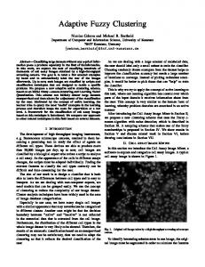
3. Methodology 3.1 The Original Low-Energy Adaptive Clustering Hierarchy LEACH algorithm is a cluster members elect a cluster head to avoid excessive energy consumption [10]. LEACH is a self-organizing, adaptive clustering protocol that uses randomization to distribute the energy load evenly among sensors in the network as shown in Fig.1. In LEACH, the nodes organize themselves into local clusters, with one node acting as the local BS or cluster-head. If the cluster heads were chosen as priori and fixed throughout the system lifetime similar to conventional clustering algorithms, it is easy to see that the unlucky sensors chosen to be cluster-heads would die quickly, ending the useful lifetime of all nodes belonging to those clusters.
Fig. 1 The LEACH protocol for Wireless Sensor Network. LEACH protocol includes the sensor nodes, which randomly organize into a local cluster with one becoming the cluster head. The LEACH consists of 2 phases: set-up phase and steadyphase. In the setup phase, sensors can be selected randomly among themselves as a local cluster head with a certain probability. By doing so, the network may balance energy dissipation across the whole network. The optimal number of cluster heads is 5% of the total. After the cluster heads are selected, the heads advertise to all sensor nodes in the network that they are new cluster heads. Once the nodes receive the advertisements, they decide which head they belong. In the steady-phase, sensors sense and transmit data to the sink through their cluster heads. In the same manner, other clustering routing protocols, transmits their information to the sink, and thus, they make mono-level hierarchy in WSNs. After a certain period spent in the steady state, the network goes into the setup phase again and enters another round of selecting cluster heads [10]. Heinzelman et al. [7] LEACH forms clusters using a distributed algorithm in which nodes make autonomous decisions without any central control. In the beginning of round r + 1 (which start at time (t)) with probability T(n), let each sensor n selects itself to be CH. T(n) is chosen such that the expected number of CH nodes for this round is k. Thus, if there are N nodes in the network then: (1) Ensuring that all nodes are CH, the same number of times requires each node to be a CH one in rounds on average. If Cn(t) is the indicator function to determine whether node has been a CH in the most recent (r mod rounds i.e Cn(t) = 0, if node has been a CH and one otherwise), then each node should choose to become a CH at round r with probability (2)
This means that only nodes that have not previously been a CH and considered to have more energy available from the node that recently have intensive energy function can be a CH at round r + 1. The expected number of nodes that have not been a CH in the first rounds r is N – K × r. After rounds, all nodes expected to have been CH once, following which they are eligible to perform this task in the next sequence of rounds. Since Cn(t) is one if node n is eligible to be a CH at time t and zero otherwise, the term represent the total number of nodes that are eligible to be a CH at time t and (3) This ensures that all nodes are having approximately equal energy after (2) and (3), the expected number of CH per round is
rounds. Using Eqns.
(4) Each CH dissipates energy receiving signals from the nodes beam forming the signals and transmitting the aggregate signal to the BS. Since the BS is located away from the nodes, it can be assumed that the distance of BS is greater than the crossover distance and the energy dissipation follows a two-ray ground model (e.g d4 power loss). The energy dissipated in the CH node during a single frame can be expressed as: (5) Where l is the number of bits in each data and d4toBS is the distance from the CH to the BS. Finally, when a node has selected itself as a CH based on Eqn. 2, it broadcasts an advertisement message informing all nodes that it is a cluster head. This advertisement is done using Carrier Sense Multiple Access (CSMA) protocol. Non-cluster heads use these messages from the cluster heads to choose the cluster they want to belong for this round based on the received signal strength of the advertisement message. 3.2 The Propose Modification of the Low-Energy Adaptive Clustering Hierarchy protocol LEACH uses a distributed algorithm for the formation of the cluster head node, each node make decisions by itself without a central control. In the case of MoLEACH, the cluster head is selected randomly and nodes become the cluster head if cluster heads have the same initial energy. To increase the lifetime of the networks, the MoLEACH uses a probability function while considering the use of node residual energy for cluster configuration whereas LEACH only utilizes a probability function. In the case of the nodes which do not have the same amount of energy (for second round and afterward), the nodes with higher residual energy will become a CH more often than nodes that have less energy to ensure that all nodes die approximately at the same time. This can be achieved by setting the probability of becoming a cluster head as a function of a node’s energy level relative to the aggregate energy remaining in the network, rather than purely as a function of the number of times the node has been head clustered, thus,
(6)
where p is the desired percentage of cluster heads, r is the current round number, G is the set of nodes that have not been CHs in the last rounds, Eresidual is the current residual energy of node and (7) where Etotal is the total energy of the entire network and by using these probabilities, the nodes with higher energy will become cluster heads rather than nodes with less energy. The expected number of cluster head nodes is given by Eqn. (8) (8) The optimal value of cluster, k can be determined as explained in the original LEACH. To calculate the threshold value (Eqn. 6) for nodes to become CH for the next round, it is essential for each node to transmit their current residual energy to BS so that the total energy for entire network can be calculated using Eqn. 7. This process is done in pre set-up phase which is the improvement on the original LEACH [7]. The the flow chart and pseudo code of the proposed MoLEACH are depicted in Fig. 3 and Fig. 4. The three phases of the MoLEACH are described as follows: 3.2.1 Set-up Phase Each node generates a random probability (pn) at the beginning of a new round and computes the threshold value T (n) by using Eqn. 6. If r = 1 (i.e. the first round) and Eresidual for each node are the same. In case of pn < p, the node is selected as a CH. A selected CH broadcasts an advertised message over neighbor nodes. The neighbor nodes collect advertised messages during a given time interval and then send a “join REQ” message to the nearest CH. The cluster head receives the “join- REQ” messages and builds a cluster member list and a Time Division Multiple Access (TDMA) schedule. Subsequently, broadcast over neighbor nodes. The member node receives and save the message for data transfer. 3.2.2 Steady-state phase The timeline of the proposed MoLEACH algorithm, the steady-state operation is divided into frames. The main activities in this phase are sensing and transmission of sensed data. Each sensor nodes senses and transmits the sensed data to its CH according to TDMA table as shown in Fig. 2. In addition, for next round to occur, it is required for the cluster node to transmit together their current energy and their ID’s. When data and energy status has been received, the CH performs data fusion and aggregation in order to reduce the amount of data. Finally, each CH transmits data to BS along the CH-to-CH routing path which have been formed during the setup phase.
Fig. 2 MoLEACH algorithm TDMA frame 3.2.3 Pre set-up Phase Before the last frame of a round completes, the CH sends BS the residual energy value of each nodes that belong to its own cluster. BS collects all residual energy values from CHs, finds the total residual energy value (Etotal) of the network, and Etotal back to CHs. The CH broadcasts Etotal over cluster nodes. Each nodes save the value of Etotal for the next computation of T(n) and the current round is terminated.
Fig. 3 Pre set-up phase for MoLEACH algorithm
BEGIN 1) Specify the probability, p and the number of nodes; (nrNodes) // p is set to 0.05 2) Eresidual (n) = E0 , n = 1,2,…,m; // initial energy for each nodes SET-UP PHASE 3) Compute threshold value T (n); 4) While (cluster head counts < Needed cluster head, p) && (node < nrNodes) 5) Assign a random number to each nodes; 6) If (random number < threshold value); 7) Cluster head = TRUE; //only 5% nodes become cluster head 8) Else 9) Cluster head = FALSE; 10) End if 11) If ( CH (n) = TRUE) then 12) BC (ADV) ; //Broadcast and advertisement message 13) Join (IDi); // non-cluster head node i join into the closest cluster head 14) Cluster c; // form cluster c 15) End if STEADY-STATE PHASE 15) If (CH (n) = TRUE) then 16) Receive (IDi, DataPCK); // Received data packet and residual energy from members 17) Aggregate (IDi, DataPCK); // aggregate receive data and residual energy 18) SendtoBS (IDi, DataPCK); // transmit receive data and residual energy to BS 19) Else 20) If (MyTimeSlot = TRUE) then 21) SendtoCH (IDi, DataPCK); // transmit sensed data 22) Else 23) SleepMode (n) = TRUE; // node n in sleep mode 24) End if 25) End if //round done for first round PRE SET-UP PHASE 26) statusNodeReceive (IDi, DataPCK); // received data and residual energy from cluster head 27) for (n = 0; n < total node; n++) 28) calculate TotalEnergy = ; // Calculate maximum residual energy 29) BC (MaxEnergy); // Broadcast maximum residual energy to the network through CH 30) Go to 1; // Start for second and next round
Fig. 4 Pseudo-code of the MoLEACH Algorithm 3.4 Implementation of MoLEACH 3.4.1 Snapshot of OMNET++ Simulation for moLEACH Algorithm The development of moLEACH under OMNeT++ requires a NED (module description) and a C++ (functionality description) for implementation. For that purpose, we use the solar-LEACH simulation developed by Voigt et al. [11]. The NED file for moLEACH algorithm was developed using GNED editor in OMNeT++ version 4.1. GNED is a graphical environment, facilitating the development and debugging of simulation topologies. Fig. 5 is the graphical and text representations of model topologies that can be used interchangeably so that editing, visualization and parameter setting can be done in the text or graphical views. GNED supports two views of the model topology: graphical editing view, which is the default view, the simulator
starts up and display the NED source code editor (see Fig. 5).
Fig. 5 Graphical and source view for LEACH implementation in GNED editor 3.4.2 Experiment Setup The layout of the MoLEACH network is shown in Fig. 6; the nodes are randomly distributed in the field region.
Fig. 6 Node Detail for LEACH network The network started the setup phase by sending status of the nodes to the BS. Each node has a random number to calculate the threshold value and determine the CH as depicted in Fig. 7 .
Fig. 7 Each node sends its status to the BS The red nodes are the CHs that have been chosen for comparing the random number to the threshold value as shown in Fig. 8.
Fig. 8. Cluster head formation in LEACH network simulation After a selection of CHs, the algorithm Moloch proceeds with a steady - state phase where TDMA schedule is created as shown in Fig. 9.
Fig. 9 TDMA schedule creation Fig. 10 shows the data sensed by nodes which is transmitted to CH and thus, the data were aggregated to BS and Fig. 11 shows the nodes after a couple of rounds.
Fig. 10 Data gathering by the nodes
Fig. 11 Snapshot after a couple of rounds 3.4. 3 Implementation of LEACH Algorithm for evaluation The LEACH C++ implementation consists of two different files: the header (.h) file, which contains forward declarations of variables, structures and subroutines, and source (.cc) file, which contains the implementation of the LEACH algorithm. 3.4.4 Initialization of The Module Network Parameters The initialization of the network parameters was made through the omnetpp.ini file, a simulation initialization file required to set the initial simulation values. The parameters and their corresponding values are: 3.4.5 Generic parameters: (omnetpp.ini) i. solar.numNodes: Number of sensor nodes in the network ii. solar.xMax: Maximum x-position on grid of the node iii. solar.yMax: Maximum y-position on grid of the node iv. solar.rounds: Number of rounds for which the solution is to be run v. solar.frames: Number of frames sent to head by each node in cluster 3.4.6 Simulation Parameters For the purpose of simulation, the simple radio model was adopted from [7]. The described model in the referred source assumes energy dissipation of Eelec = 50 nJ/bit to run the transmitter or receiver circuitry and Eamp = 100 pJ/bit/m2 for the transmit amplifier to achieve
an acceptable (Signal to Noise Ratio). The first order radio model is as shown in Fig. 12. Other parameters used in the simulation are described in Table 1 and Fig. 13 display screenshot of the parameter settings in the simulator.
Fig. 12. First order radio model [7] Table 1 Parameters used in the simulation Type Network
Application
Radio Model
Parameter Network Grid (3 × 3)
Value From (0,0) to 1) (500, 500), to 2) (1000,1000) and to 3) (1500, 1500)
Base Station
100, 150, 200 meter
Initial Energy
0.5 Joule/battery/node
Node Distribution (N)
100 nodes randomly distributed
Rounds (frame)
5, 10, 20, 25 TDMA frames
Broadcast packet size
25 bytes
Packet header size
25 bytes
Transmitter energy consumption (ETXelec) Receiver energy consumption (ERX-elec) (ETX-elec = ERX-elec = Eelec) Amplifier energy consumption (Eamp)
50 nJoule/bit 50 nJoule/bit 100 pJ/bit/m2
It also assumes that, an r2 energy loss due to the channel transmission. Thus, to transmit and receive a k-bit message a distance (d) using this radio model, the radio expends as expressed in Eqn. (9) and (10):
(9) (10)
where λ represent a path-loss exponent. The value of these parameters makes the message transmission and reception not low cost operations. Therefore, the protocols should minimize the number of transmit and receive operations by means of switching its state between active and sleep (or idle) when required in order to minimize the energy consumption. 3.5 Testing Parameters for the Simulation In order to obtain multiple results, a series of test has been prepared for the different routing protocols earlier described. The network grid shows the different areas of the network used in the simulations (500x500 m2, 1000x1000 m2 and 1500x1500 m2 ) as shown in Fig. 12. Each of these areas has been simulated in which the BS was set to 100, 150 and 200 meters to the closest node of the network to find out the behavior of the protocols when the BS is placed at different distances far from the sensor nodes. For each of the conditions, each protocol has been simulated with rounds comprised of 5, 10, 20 and 25 TDMA frames, which results in a short or long steady-state phase (see Fig. 3). All the parameters implemented in omnetpp.ini file in OMNeT++ were altered each time the simulation is executed.
Fig. 13. Omnetpp.ini file for parameter setting Therefore, based on the initial energy parameter (see Table 1), a full-charged battery energy level of 0.5 Joules has been chosen, since it is sufficient to see the differences in the results among the different protocols evaluated. In all the simulations, the network always consists of 100 nodes. Hence, in large area networks such as 1500x1500 m2, the node density is lower than in small area networks such as 500x500 m2.
4 Results and discussion 4.1 First Node Dead In the case of a short steady phase and a small area network, the MoLEACH gets better results, by achieving more than 2 times the lifetime of the LEACH as shown in Fig. 14.
Rounds Done
500 X 500 & 5 Frames 400 300 200 100 0
MoLEACH LEACH 100
150 BS Distance (m)
200
(a)
Rounds Done
1000 X 1000 & 5 Frames 400 350 300 250 200 150 100 50 0
MoLEACH
LEACH
100
150
200
BS Distance (m)
(b)
Rounds Done
1500 X 1500 & 5 Frames 400 350 300 250 200 150 100 50 0
MoLEACH LEACH
100
150
200
BS Distance (m)
(c) Fig. 14. Number of rounds when the first node is dead in LEACH and MoLEACH for 5 frames in different BS distances. When the node density decreases or the area, network increases, the results of both protocols get closer, but MoLEACH still have better results as shown in Fig. 15.
Rounds Done
500 X 500 & 10 Frames 200
100
MoLEACH
0
LEACH
100
150
200
BS Distance (m)
(a)
Rounds Done
1000 X 1000 & 10 Frames 200 150 100 50 0
MoLEACH LEACH
100
150
200
BS Distance (m)
(b) 1500 X 1500 & 10 Frames Rounds Done
150 100 MoLEACH
50
LEACH
0 100
150
200
BS Distance (m)
(c) Fig. 15 Number of rounds when the first node is dead in LEACH and MoLEACH for 10 frames in different BS distance. If the duration of the steady-state phase increases, the lifetime of both protocols will decrease as observed in Fig. 16. The results show that the MoLEACH outperforms the performance of LEACH as shown in Fig. 17.
(a)
1000 X 1000 & 20 Frames Rounds Done
80
60 40
MoLEACH
20
LEACH
0
100
150
200
BS Distance (m)
(b) 1500 X 1500 & 20 Frames Rounds Done
80 60 40 MoLEACH
20
LEACH
0 100
150
200
BS Distance (m) (c)
(c) Fig. 16 Number of rounds when the first node dead in LEACH and MoLEACH for 20 frames in different BS distance
Fig. 17 indicates the results of both protocols with 20 frames. It shows that the network lifetime becomes shorter as previously mentioned, but MoLEACH still get the highest number of rounds before first node dead. It can also be seen that the more the distance from the BS to the node, the more network lifetime is decreased.
500 x 500 & 25 Frames
Rounds Done
50 40
30 20
MoLEACH
10
LEACH
0 100
150
200
BS Distance (m)
(a) 1000 x 1000 & 25 Frames
Rounds Done
50 40 30 20
MoLEACH
10
LEACH
0 100
150
200
BS Distance (m)
(b)
1500 x 1500 & 25 Frames Rounds Done
50 40 30 MoLEACH
20
LEACH
10 0 100
150
200
BS Distance (m)
(c) Fig. 17 Number of rounds for the first node dead in LEACH and MoLEACH for 25 frames from different BS distance The results of the two protocols (MoLEACH and LEACH) obtain in a steady-state phase of 25 frames, shows that both protocols have short lifetime when the steady-state phase is long. The results further indicated that even though the network lifetime decreases, MoLEACH network was found to be 2 times better than LEACH. It can be observed in Figs.14-17 that in the long steady-state phase, the network lifetime for both the protocols decreases as explained earlier. The proposed MoLEACH prolong the network lifetime. The consideration of node residual energy during cluster head selection, processing can maintain the balanced energy consumption of the sensor network. 4.2 Half Node Dead The analysis of the half node dead is performed to observe the overall performance of LEACH and MoLEACH. Comparison among all the protocols in the rounds was achieved until half of the nodes are dead. It is clear that the number of half node dead in MoLEACH occur in the rounds about 2 times as in the first node dead as shown in Fig. 18. The more the network size increase, the more the network lifetime of MoLEACH and LEACH protocols decreases.
(a)
(b)
(c) Fig. 18 Number of rounds when the half node dead in LEACH and MoLEACH for 5 frames from different BS distance. Steady-state that is formed by 10 frames in a small and large area network is explained based on Fig. 19. In the case of a steady phase formed by 20 frames, the results of both protocols show a similar behavior in the previous case. Their respective outcomes get closer to each other in a
large area network, but LEACH shows more constant behavior than the MoLEACH with the BS placed at different distances.
(a)
(b)
(c)
Fig. 19 Number of rounds when the Half Node Dead in LEACH and MoLEACH for 10 frames from different BS distance
(a)
(b)
(c)
Fig. 20 Number of rounds when the Half Node Dead in LEACH and MoLEACH for 20 frames from different BS distance. When the steady phase has double the number of frames of the previous case, the behavior of both protocols remains the same, but decreasing the number of rounds will achieve almost half of the protocol's behavior as shown in Fig. 20. This situation can be explained as an example of a low-cost set-up phase in energy terms, whereas the high cost steady-state phase is due to a nonoptimal election of the cluster heads and the direct communication between cluster heads and base station. It can also be observed that the farther the BS from the nodes, the more the network lifetime is decreased.
(a)
(b) Fig. 21 Number of rounds when the Half Node Dead in LEACH and MoLEACH for 25 frames from different BS distance. In this scenario the results of both protocols with the longest steady phase simulated outcomes are really similar to the previous ones as expected, but decreasing the overall amount of rounds achieved. By analyzing the result from Figs.18-21, modified LEACH still achieves a higher
number of rounds, but it decreases as the TDMA frame increases. The network lifetime for both protocols becomes worse as the network size increases. As the network size and TDMA frame increases, the result for both protocols become closer to each other. 4.3 Effect of Number of Nodes to the Network Lifetime The simulation was performed to study the effect of different number of nodes on the network lifetime. In the simulation 50, 75 and 100 nodes were implemented in 500 x 500 m2, 1000 x 1000 m2 and 1500 x 1500 m2 network sizes.
(a)
(b) Fig. 22. First Node Dead results for different nodes implemented in different network size The first node dead comparison for different number of nodes and network size is shown in Fig. 22, when the number of nodes increases, the network lifetime decreases for both protocols. For larger number of nodes and bigger network size, the network lifetime becomes closer to each other, but MoLEACH has shown improvement over LEACH. It can also be observed that the LEACH shows a stable network lifetime for bigger network size, whereas MoLEACH shows
that the network lifetime decreases linearly and outperform the LEACH.
(a)
(b) Fig. 23 Half Node Dead results for different nodes implemented in different network size Half Node Dead for both protocols decrease with the increment of the number of nodes as depicted in Fig. 23. The network size increases, the network lifetime shows a slight decrement. But as mentioned earlier in the above analysis, it is concluded that performance of modified LEACH is still better than LEACH. 4.4 Improvement made by MoLEACH The network lifetime improvement of MoLEACH over LEACH is described in this section. From the simulation and analysis in the preceding sections, the network size and the TDMA frames affect the performance of the network lifetime in WSNs. The percentage of improvement made by MoLEACH over the original LEACH is computed and reported in Table 1.
The improvement of MoLEACH is greater with short steady-state phase, small network size and closeness of BS distance from the nodes. This is expected because the energy used to aggregate data, when BS is closer is less than energy if the BS distance is far away. When the steady-state becomes longer, the improvement becomes less, yet, MoLEACH shows a better network lifetime than the LEACH. For First Node Dead improvement, the shorter steady-state phase shows only a slight improvement over LEACH. The improvement becomes worse, when the BS distance is far away both protocols almost have the same performance. It shows that the steady-state phase improvement of MoLEACH is better than the original LEACH in short distance. Table 2. Percentage of improvement made by MoLEACH for First Node Dead MoLEACH Improvement for Healthcare Applications Area Network(m²)
500 x 500
1500 x 1500
BS distance (m)
100
150
200
100
150
200
5 frames (%)
67
65
71
43
60
50
25 frames (%)
9
6
4
12
17
10
4.5 Distribution of Energy in LEACH and Modified LEACH The distribution of energy in LEACH algorithm is uneven between the node if the CH becomes unreasonable. The proposed MoLEACH has encountered this problem by taking into account the node’s residual energy in selecting the CH for the purpose of simulation, each node is supplied with 0.5 Joule battery. Fig. 24 shows the energy distribution between each node for LEACH and MoLEACH after the simulation.
Fig. 24 Energy distributions in LEACH and MoLEACH In LEACH, there is a different amount of energy for cluster formation at the beginning of each round, as the total energy depends on the number of nodes that select themselves to be CH and their locations from the network. A large number of CH nodes imply that more energy is dissipated in the network. Thus, the MoLEACH shows more energy-efficient than the original LEACH in which better cluster can be determined than the distributed algorithm used in the LEACH. The probable reasons for the energy efficiency of the MoLEACH can best be explained by the following two possibilities: (1) The MoLEACH used a probability function while considering the use of node residual energy for cluster configuration which could have probably improved the energy efficiency of the MoLEACH. (2) The probability function might have improves the CH selection by taking into account the residual energy of each node for threshold calculation before another round started. The MoLEACH can effectively replace the LEACH in healthcare application systems such as in-home monitoring, in-hospital monitoring, ambulatory monitoring, vital sign monitoring in-hospitals, monitoring elderly people at home care, monitoring in mass-casualty disasters and clinical monitoring for automatic patient monitoring without disturbing patient comfort by the need for frequent recharging or replacement of batteries.
5. Conclusions In this paper, we proposed to modify LEACH to improve its energy efficiency in WSNs for healthcare applications. The original LEACH was modified in the research and code name as MoLEACH. The MoLEACH and the LEACH has been implemented in the OMNeT++ and evaluated in different simulation scenarios of large scope clustered type networks. The evaluation of the simulation scenarios was performed using several testing parameters such as TDMA frames in different network sizes, BS distances, number of nodes, network size, First Node Dead and Half Node Dead. The simulated comparative analysis of the results clearly indicates that the performance of MoLEACH in terms of network lifetime outperforms the LEACH. Thus, the MoLEACH advance the energy efficiency of the original LEACH. Therefore, it can be determined that the MoLEACH proposed in this study can be implemented in the design of HCWSNs architecture for effective, robust, energy efficient and promising applications
in healthcare systems to significantly reduce the need for frequent recharging or replacement of batteries. Conflict of Interests “The authors declare that there is no conflict of interests regarding the publication of this paper” Acknowledgment. This work is supported by High Impact Research Grant University of Malaya no vote UM.C/628/HIR/MOHE/SC/13/2. References 1 Akyildiz IF, Su W, Sankarasubramaniam Y, Cayirci E: Wireless sensor networks: A survey. Computer Networks, 2002, 38(4): 393-422. 2 Anastasi G, Conti MD, Francesco M, Passarella A: Energy conservation in wireless sensor networks: a survey. Ad Hoc Networks, 2009, 7(3): 537–568. 3 Malan D, Fulford-Jones T, Welsh M, Moulton–CodeBlue S: An ad-hoc sensor network infrastructure for emergency medical care. International Workshop on Wearable and Implantable Body Sensor Networks, 2004, 4(5): 12-14. 4 Wang L, Xiao Y: A survey of energy-efficient scheduling mechanisms in sensor networks. Mobile Network Application, 2006, 11(5): 723-740. 5 Tilak S, Abu-Ghazaleh NB, Heinzelman W: A taxonomy of wireless micro-sensor network models. ACM SIGMOBILE, 2006, 6(2): 28-36. 6 Yick J, Mukherjee B, Ghosal D: Wireless sensor network survey. Computer Networks. 2008, 52(12): 2292-2330. 7 Heinzelman WR, Chandrakasan A, Balakrishnan H: Energy-efficient communication protocol for wireless microsensor networks. Proc. of the 33rd Hawaii International Conference on System Sciences, IEEE Explore. New Delhi, 2010, 1-10. 8 Young Jang K, Kim K, Yong Youn H: An energy efficient routing scheme for wireless sensor networks. International Conference on Computational Science and its Application (ICCSA). Kuala Lumpur, Malaysia 2007, 195-206. 9 Hande A, CemErsoy E. Wireless sensor networks for healthcare: a survey. Computer Networks, 2010; 54(15): 2688–2710. 10 Tao L, Qing-Xin Z, Luqiao Z: An improvement for LEACH algorithm in wireless sensor network. Proc. of the 5th International Conference on Industrial Electronics and Application. IEEE Explore, 2010, 1811-1814. 11 Varga A: OMNeT++ Manual. http://www.omnetpp.org, 2002-03-16/2003-11-02.