the use of formal verification to ensure that processes satisfy safety ... on the first page. To copy ...... In Proceedings of IEEE International EDOC Confer- ence ...
Modular Context-Sensitive and Aspect-Oriented Processes with Dynamic Condition Response Graphs Thomas Hildebrandt1 1
Raghava Rao Mukkamala1
Tijs Slaats1,2
Francesco Zanitti1
IT University of Copenhagen, Rued Langgaardsvej 7, 2300 Copenhagen, Denmark 2 Exformatics A/S, Lautrupsgade 13, 2100 Copenhagen, Denmark {rao, hilde, tslaats, zanitti}@itu.dk
Abstract
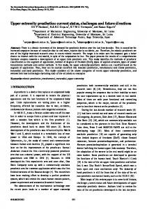
discuss how merging is similar to adding advices and weaving of aspects in AOP. The examples also show how the join operator can We propose the recently introduced declarative and event-based be used to refine and more generally adapt behavior of a process, Dynamic Condition Response (DCR) Graphs process model as a i.e. by replacing an event or a complete sub process with a new formal basis for modular implementation of context-sensitive and process. aspect-oriented processes. The proposal is supported by a new join It should be stressed that the proposal in the present paper is operator allowing modular composition and refinement of DCR very initial work. The DCR Graph model was developed with anGraphs. We give small illustrative examples of DCR Graphs definother application area in mind as a foundation for flexible working context-sensitive processes where context-events dynamically flow languages as part of the second author’s PhD project [12]. enable and disable the need for authentication and the join operaIt has then subsequently been continued in the (ongoing) PhD tor is used to add authentication to a process. Finally, we discuss projects of the third and fourth authors focussing on respectively the use of formal verification to ensure that processes satisfy safety developing a formal foundation for the implementation of flexiand liveness properties, and define two liveness properties (deadble, cross-organizational workflow systems [5] and developing a lock freedom and liveness) that can be verified directly on the state process-oriented event-based programming language (PEPL) [4] graph for DCR Graphs. for context-sensitive services based on DCR Graphs. In Fig. 1 below we give a concrete example of a contextCategories and Subject Descriptors D.3.1 [Programming Lansensitive authorization process that we will use as running example. guages]: Formal Definitions and Theory - Semantics, Syntax The example is inspired by a concrete case study of an oncology General Terms Design, Languages, Reliability, Verification workflow process at a danish hospital [11]. The graph consists of five events (shown as boxes). Each event corresponds to the (possibly repeated) execution of an activity, 1. Introduction which is indicated by a label assigned to the event and shown inside The terms context-sensitivity, context-awareness and context-dependency the box. The activities in the example are thus action, authorize, are generally used to describe systems that adapt their behavior acreauthorize, normal and emergency. cording to changes in their context. Changes in the context are naturally described as events, either provided by sensors, user inputs or messages from other programs. This suggests the application of event-driven programming to implement context-aware systems. Event-driven systems are normally based on the publish-subscribe pattern. That is, at any time the system subscribes to specific (patterns of) events. Whenever a pattern has been detected, the system reacts by performing a block of code, possibly publishing new events. In the present paper we propose to use the recently introduced event-based declarative process model, Dynamic Condition Response Graphs (DCR Graphs) [3, 6, 7, 13], as a formal basis for modular and aspect-oriented construction of context-sensitive systems. The modular and aspect-oriented construction is facilitated by a new, general join operator. We give small examples that illustrate how the join operator can be used to merge processes, and Figure 1. Context-sensitive authorization process as DCR Graph.
Permission to make digital or hard copies of all or part of this work for personal or classroom use is granted without fee provided that copies are not made or distributed for profit or commercial advantage and that copies bear this notice and the full citation on the first page. To copy otherwise, to republish, to post on servers or to redistribute to lists, requires prior specific permission and/or a fee. FOAL’13, March 26, 2013, Fukuoka, Japan. c 2013 ACM 978-1-4503-1865-5/13/03. . . $15.00 Copyright
One way to think of a DCR Graph is as an event-driven reactive program, where the code-blocks usually executed when an event pattern is detected have been replaced by specifications of response events, specifying activities that must eventually be executed (by the process or the environment) whenever possible. That is, the occurrence of an event schedules other events that must be executed in the future in order for the process to progress. The response events are specified in the graph by the response relation, indicated
graphically by the arrow with a bullet at the source and coloured blue to make it more easily visible. In the example we thus have a response relation from the reauthorize to the authorize event. Moreover, every event can have a list of condition events and milestone events. In order for an event to be enabled, i.e. its activity to be executable, its condition events must have been executed at least once in the past and its milestone events must not currently be scheduled for execution. In the example, the authorize event is a condition for the reauthorize event and a milestone for the action event. The condition relation means in this example that reauthorize can not be executed if authorize has not been executed at least once in the past. The milestone relation means that the action event is blocked if an authorize event is scheduled for execution. Finally, in addition to the specification of response, condition and milestone events, a novel idea of DCR Graphs is the specification of events that are excluded and included when an event happen. Exclusion and inclusion of events have a cross-cutting effect on the system similar to turning aspects on and off in aspect oriented programming: An excluded event is ignored as condition and milestone of events and even if it is currently scheduled it will not be required to be executed unless it is included again. In the example, the event emergency excludes the authorize and reauthorize events and the event normal includes the two events. Note we use the nested DCR Graphs notation introduced in [6], a relation to a box around events is simply a short hand for having the relation to all the sub events. Now, if an emergency event happens (e.g. representing that the condition of the patient becomes critical), then the events authorize and reauthorize are excluded. This means that even if authorize is scheduled for execution and a milestone for action, then it is not disabling the action event. However, if the normal event happens, then authorize and reauthorize are again included. The five relations (condition, response, milestone, include and exclude) completely describe the dynamic behavior of the process. Moreover, the state of a running process can be described by a triple of finite sets of events, (Ex, Re, In) similar to markings of Petri Nets [15, 16]. The set Ex records the previously executed events, the set Re describes the events scheduled for execution, and the set In denotes the currently included events. The set Re thus contains events schedules as responses to events that have been executed, but we also allow to define that some events are scheduled in the initial marking of the graph. We graphically visualize a marking (Ex, Re, In) by adding a (green) checkmark to every box for events in the Ex set, a (red) exclamation mark to every box for events in the Re set, and making the border dashed of boxes for events which are not in the In set. A run of a DCR Graph is then a (possibly infinite) sequence of markings, where the (n + 1)th marking is obtained by executing one of the enabled events in the nth marking (adding it to the set Ex) and updating the Re and In sets according to the relations. An example run of the process in Fig. 1 is shown in Fig. 2. In the initial marking (at the top), nothing has been executed, the events action and authorize are scheduled, and every event is included. This state is described by the marking (∅, {action, authorize}, E), where E is the set of all five events. In this state, only the events authorize, normal and emergency are enabled. The event action is blocked because it has authorize as milestone and authorize is scheduled for execution. The event reauthorize is blocked because it has authorize as condition, and this event has never been executed. Now, if the emergency event is executed then the state changes to the marking ({emergency}, {action, authorize}, E\{authorize, reauthorize}), shown at the graph in the middle of Fig. 2. That is, emergency is recorded as executed, whereas action and authorize are still scheduled, but authorize and reauthorize are ex-
cluded. This implies that authorize is not longer considered as milestone for action, which therefore is enabled. The marking shown at the bottom of Fig. 2 shows the state if the event action is executed.
Figure 2. An example run of the authorization process. Note that action can be executed several times. However, if normal is now executed, i.e. if the patient condition is no longer critical, then system moves to the marking shown in Fig. 3, where authorize and reauthorize are included again.
Figure 3. If the normal event is executed, then authorize is again required before action can be executed. Since authorize is still scheduled in the marking in Fig. 3, the event action is not enabled and can not be executed unless
authorize is executed or excluded because the event emergency is executed again. Runs may be finite or infinite. We say that a run is accepting if whenever an event is scheduled, it eventually gets excluded or executed. As shown in [12, 13], DCR Graphs can be mapped to the standard B¨uchi-automata model, characterizing all runs as well as fair runs as the accepting runs, and subsequently verified for safety and liveness properties using the SPIN model checker [9]. However, it can also be represented directly (and more compactly) as a so-called transition system with responses [2], which is simply a labelled transition system where each state is annotated by a set of labels, referred to as the response actions. The accepting runs of a transition system with responses is then the finite or infinite runs where whenever a label is included in the response set of an intermediate state in the run, it will be excluded from the response set in a subsequent state or executed. It is worth stressing that there is no explicit sequencing of commands in the DCR Graphs process model. This makes it possible to weave, refine and adapt processes by the general join operator introduced in Sec. 3. If a new event is joined as a milestone for some existing events in a process, and such that this new event is scheduled whenever the existing events are scheduled as responses, then the new event must be executed before the existing events become enabled. Thus, the new event is similar to an advice in AOP, that must be executed before the targetted set of existing events which correspond to join points. After briefly recalling the formal definition of DCR Graphs in Sec. 2, we exemplify this aspect-oriented modularity in Sec. 3 where the DCR Graph shown in Fig. 1 is joined with a another process describing a context-sensitive request/reply process shown in Fig. 4 We end by briefly summarizing the techniques for formal verification and distribution of DCR Graphs developed so-far in the above mentioned research projects and briefly touch on related work.
2.
DCR Graphs
In this section we give the formal definitions of DCR Graphs. We employ the following notation. Notation: For a set E we write P(E) for the power set of E (i.e. set of all subsets of E). For a binary relation →⊆ E × E and a subset ξ ⊆ E we write → ξ and ξ → for the set {e ∈ E | (∃e0 ∈ ξ | e → e0 )} and the set {e ∈ E | (∃e0 ∈ ξ | e0 → e)} respectively, and abuse notation writing → e and e → for → {e} and {e} → respectively when e ∈ E. Formally, a DCR Graph is defined as follows. D EFINITION 1. A Dynamic Condition Response Graph (DCR Graph) G is a tuple (E, M, →•, •→, →�, →+, →%, L, l), where (i) E is a set of events, (ii) M ∈ isthemarking, P(E) × P(E) × P(E), (iii) →•, •→, →�, →+, →%⊆ E × E is the condition, response, milestone, include and exclude relation respectively. (iv) L is the set of labels and l : E → P(L) is a labeling function mapping events to labels. As explained in the introduction, the marking (ii) represents the state of the DCR Graph and the five binary relations over the events (iii) define the constraints on the events and dynamic inclusion and exclusion. Finally, each event is mapped to a set of labels (iv). In Def. 2 we formally define that an event e of a DCR Graph with marking M = (Ex, Re, In) is enabled, written G ` e, when e is included in the current marking, i.e. e ∈ In, and all the included events that are conditions for it are in the set of executed events, i.e. (In∩ →• e) ⊆ Ex, and none of the included events that are
milestones for it are in the set of scheduled response events, i.e. (In∩ →� e) ⊆ E\Re. We then further define the change of the marking when an enabled event e is executed: Firstly, the event e is added to the set of executed events (Ex ∪ {e}). Secondly, the event is removed from the set of scheduled responses and all events that are a response to the event e are added to the set of scheduled responses ((Re \ {e}) ∪ e •→). Note that if an event is a response to itself, it will remain in the set of scheduled responses after its execution. Finally, the included events set is updated to the set (In\e →%)∪e →+, i.e. all the events that are excluded by e are removed, and then all the events that are included by e are added. D EFINITION 2. For a Dynamic Condition Response Graph G = (E, M, →•, •→, →�, →+, →%, L, l), and M = (Ex, Re, In) we define that an event e ∈ E is enabled, written G ` e, if e ∈ In ∧ (In∩ →• e) ⊆ Ex and (In∩ →� e) ⊆ E\Re. We further define the result of executing the event e as (Ex, Re, In) � ⊕G e =def Ex ∪ {e}, (Re \ {e}) ∪ e •→, (In \ e →%) ∪ e →+ . Having defined when events are enabled for execution and the effect of executing an event we define in Def. 3 the notion of finite and infinite executions and when they are accepting. Intuitively, an execution is accepting if any event which is scheduled and included in any intermediate marking, is eventually executed or excluded. D EFINITION 3. For a Dynamic Condition Response Graph G = (E, M, →•, •→, →�, →+, →%, L, l) we define an execution of G to be a (finite or infinite) sequence of tuples {(Mi , ei , ai , M0i )}i∈[k] each consisting of a marking, an event, a label and another marking (the result of executing the event) such that M = M0 and ∀i ∈ [k].ai ∈ l(ei ) ∧ Gi ` ei ∧ M0i = Mi ⊕G ei and ∀i ∈ [k − 1].M0i = Mi+1 , where Gi = (E, Mi , →•, •→, →�, →+, →%, L, l). We say the execution is accepting if ∀i ∈ [k]. ∀e ∈ Ini ∩ Rei .∃j ≥ � i.ej = e ∨ e 6∈ In0j ) , where Mi = (Exi , Ini , Rei ) and M0j = (Ex0j , In0j , Re0j ). Let exeM (G) and accM (G) denote respectively the set of all executions and all accepting executions of G starting in marking M. Finally we say that a marking M0 is reachable in G (from the marking M) if there exists a finite execution ending in M0 and let MM→∗ (G) denote the set of all reachable markings from M. A marking in a DCR Graph is accepting, if there are no included scheduled events that required as responses. Thus, a deadlock state can be defined as a state where there is an included scheduled event, but without any enabled events. We say that a DCR Graph is deadlock free if and only if there is no reachable deadlock state. D EFINITION 4. For a dynamic condition response graph G = (E, M, →•, •→, →�, →+, →%, L, l) we define that G is deadlock free, if ∀M0 = (Ex0 , In0 , Re0 ) ∈ MM→∗ .(∃e ∈ E.G0 ` e ∨ (In0 ∩ Re0 = ∅)), for G0 = (E, M0 , →•, •→, →�, →+, →%, L, l). A DCR Graph is defined to be live if and only if, in every reachable marking, it is always possible to continue along an accepting run. D EFINITION 5. For a dynamic condition response graph G = (E, M, →•, •→, →�, →+, →%, L, l) we define that the DCR Graph is live, if ∀M0 ∈ MM→∗ .accM0 (G) 6= ∅.
3.
Process Composition
In this section we define a new general join operation on DCR Graphs which supports modular, aspect-oriented composition and refinement of DCR Graphs. The join operation is defined relative to two join relations C and B, which specify which events in the left (right) graph are replaced by events in the right (left) graph.
In particular the join operation allows in special cases for basic union of graphs and refinement of events, that is, substituting an event by an entire new sub graph. Before giving the formal definition, we will give an example of how to join a process graph with another, where one event in the former graph is refined by two events in the latter process. The DCR Graph Grr in Fig. 4 below shows a process for a context-sensitive request/reply pattern.
a convinient way to represent relations to both authorize and action. To ease readability we may adopt a programming language notation for the join operation, writing the above join as follows. Listing 1. Using Join to Authorize a Reply CSRequestReplyAuth = j o i n C S R e q u e s t R e p l y and C S A u t h o r i z a t i o n where r e p l y < { a u t h o r i z e , a c t i o n }
Below we give the formal definition of the join operator. D EFINITION 6. Assume DCR Graphs Gi = (Ei , Mi , →•i , •→i , →�i , →+i , →%i , Li , li ) where Mi = (Exi , Rei , Ini ) for i ∈ {1, 2} and join relations C: E1 * P(E2 ) and B: E2 * P(E1 ). The join of G1 and G2 relative to C and B is defined as G1 CB G2 = (E, M, →•, •→, →�, →+, →%, L, l), where
Figure 4. A context-sensitive request/reply process If a request event happens, the reply is scheduled as response. The reply event is excluded if it is executed, or a cancel event subsequently happens. However, it will be included (and scheduled) again if a new request event happens. As for the example given in the introduction, the cancel event may be triggered by some change of conditions in the context of the process. We can now use the join operation to define a context-sensitive request/reply process where the reply needs (context-sensitive) authorization as defined in the DCR Graph Gauth given in Fig. 1 in the introduction. The intention is to merge the two process graphs, but such that the reply event in Grr is replaced by the authorize and action events in Gauth . The result is the graph shown in Fig. 5 and formally defined as Grrauth = Grr CB Gauth for C= {(reply, {authorize, action})} and B= ∅.
(i) ∀e ∈ dom(C). C (e) ∩ dom(B) = ∅ and ∀e ∈ dom(B). B (e) ∩ dom(C) = ∅ (ii) E = E01 ∪ E02 for E01 = E1 \dom(C) and E02 = E2 \dom(B) (iii) M = (Ex, Re, In), where: Ex = Ex1 ∩ E01 ∪ Ex2 ∩ E02 , In = In1 ∩ E01 ∪ In2 ∩ E02 and Re = Re1 ∩ E01 ∪ Re2 ∩ E02 , (iv) →=E−1 →1 ∪ →1 E ∪ D−1 →2 ∪ →2 D for each →∈ {→• , •→, →�, →+, →%} and E= {(e, e0 ) | e ∈ E1 ∧ e0 ∈C (e) ∪ {e}} and D= {(e, e0 ) | e ∈ E2 ∧ e0 ∈B (e) ∪ {e}} (v) L = L1 ∪ L2 l1 (e) ∪ l2 (e) if e ∈ E01 ∩ E02 (vi) l(e) = l1 (e) if e ∈ E01 \E02 l (e) if e ∈ E02 \E01 2 The first condition, (i), guarantees that there are no circular refinements. That is, an event in G1 can not be refined by an event in G2 which is also refined by an event in G1 and vice versa. The second condition, (ii), states that the set of events in the joined graph consists of all the events of the two graphs, that have not been refined by events in the other graph. The third condition, (iii), defines the join of the markings of the graphs. It simply inherits the markings from the two graphs. Note that the fact that markings are also joined means that we can also apply the join operator on computing processes. Condition (iv) defines the extension of the relations to the refining events. The relation E is the reflexive closure of the left join C relation, i.e. e E e0 if and only if e C e0 or e = e0 . Similarly, D is the reflexive closure of B. The relation E−1 →1 is then the relational composition of E−1 (the inverse of E) and the relation →1 , and similarly the relation →1 E is the relational composition of →1 and E. That is, e(E−1 →1 ∪ →1 E)e0 if • e →1 e0 , or • e →1 e000 and e000 C e0 , or • e00 C e and e00 →1 e0 .
Figure 5. Joining context-sensitive request/reply and authorization processes Informally, the two event sets have been joined, replacing the reply event in the graph Grr with the two events authorize and action in the Gauth graph, while inheriting all relations between the replaced event and other events in Grr . Recall, that relations to the box around authorize and action is merely
Considering our example in Fig. 5, this definition implies that e.g. cancel will exclude both action and authorize. But note that the self-exclude relation on reply, enforcing the ”linearity” constraint that only one reply can only be carried out for each request, is not kept. This is because relations between events that are replaced, and thus in particular self-relations are not kept. The rationale for not keeping these relations are that a join should allow for removing constraints on the refined events. To keep the property that the action can only be carried out once for each request, the refining graph Gauth should have an exclude relation from action to itself. Finally, conditions (v) and (vi) define the label set as the union of the two label sets, and the labeling of events by the original label for events that are not shared and the union of the label set
for shared events. Since we have not used the label function in the present paper it can safely be ignored. For the curious reader, the labeling function allows to have distinct events with the same ”external” label, which is useful for some practical applications, as well as for proving that every B¨uchi-automaton can be represented by a DCR Graph. This means in particular that the DCR Graphsmodel is more expressive that LTL. As indicated in the beginning of the section, we may derive operations G\e, G[e C G0 ] and G ∪ G0 for respectively discarding an event e, refining an event e by G0 and taking the union of two graphs G and G0 as special cases of the join operator. D EFINITION 7. For a DCR Graph G = (E1 , Mi , →•i , •→i , →�i , →+i , →%i , Li , li ) for i ∈ {1, 2} and e ∈ E1 define • (Discard) G1 \e = G1 CB G∅ where C= (e, ∅) and G∅ is the
empty DCR Graph, i.e. the DCR Graph with no events, • (Refine) G1 [e C G2 ] = G1 CB G2 where C= (e, E2 ) and
B= ∅, • (Union) G1 ∪ G2 = G1 CB G2 where C= ∅ and B= ∅.
As an example of the discard operation, we may remove the ability to cancel requests in the graph Grrauth in Fig. 5 by discarding the cancel event, taking the graph Grrauth \cancel. As an example of the refine operation, we may add the ”linearity” constraint to action in Grrauth , i.e. that it can be executed at most once for every request. This is done with a refine operation Grrauth [action C Glinact ], where Glinact is the DCR Graph ({action}, (∅, ∅, ∅), ∅, ∅, ∅, ∅, (action, action), ∅, ∅), i.e. the graph with an empty marking and a single event action related to itself by the exclude relation, and no other relations. 3.1
Aspect Oriented and Modular DCR Graphs
In an aspect oriented language based on DCR Graphs, we propose using the join operator to define an operator for adding ”before” advices for a subset of events (the joincut). This could for instance be done by refining every event e in the joincut by a DCR Graph that adds an advice sub process as a milestone before the event e, ad e.g. the authorize event before the action event in Fig. 1. Then, every time an event e in the join cut is scheduled for execution, every event in the advice sub process will also be scheduled for execution, and must be executed before executing e due to the milestone relation. Dually, an ”after” advice may be added to an event e by joining a graph that has a response, condition and include relation from e to the advice sub process, like for the request and reply events in the Grr graph in Fig. 4. This ensures that the advice must be carried out once after the event e. These two operations can then be combined to have both ”before” and ”after” advices. Toggling of advices, e.g. as a result of context-events, can be achieved by joining in events that include and exclude the advice sub processes, e.g. like the normal and emergency events in Fig. 1. One can further constrain when an advice can be toggled as in Fig. 4, where the reply action can be cancelled, but only after the request has happened. Finally, the join operator can also be considered as a general way of allowing modular definition of DCR Graphs. However, it should be stressed, that the join operator provide no guarantees for preserving safety and liveness properties. Indeed, it is easy to join graphs and achieve a circular condition dependency between events that may lead to a deadlock state if one of the events are required as response (and can not be excluded). Similarly, the join operator may introduce the possibility of a life lock, i.e. a DCR Graph with an infinite run that is not accepting and has no way of breaking out of the loop.
It is possible to verify safety and liveness properties of the composed DCR Graphs, e.g. by mapping the DCR Graph to a B¨uchiautomaton and verify the properties using the SPIN model checker as shown in [12]. This is however time consuming when the size of the processes grow. A more efficient verification currently explored is to carry out the verification on the corresponding transition systems with responses. Finally, an even more efficient guarantee of well-behaved modular composition, which we are currently investigating, is to define a notion of behavioral type for DCR Graphs based on the work on session types, which then guarantee that 1) well-typed graphs are safe and live, and 2) if compatible, welltyped DCR Graphs are joined, then the resulting graph is again well-typed.
4.
Conclusion
We have proposed the declarative, event-based DCR Graphs model as a foundation for modular construction of context-sensitive, aspect-oriented processes. Concretely, we showed how the dynamic exclusion and inclusion primitives of DCR Graphs allow to turn the relevance of events as conditions/milestones and responses for any other event in the model on and off. It was exemplified by a simple authorization process fragment, where the need for authorization can be toggled by events signaling wether the context situation is an emergency or normal. Another example was a request/reply process fragment, where the reply can be cancelled by a cancel event in the context. Moreover, we presented a new join operator for DCR Graphs, allowing both modular composition and refinement, exemplified by joining the request/reply process and the authorization process, by which the reply was refined into two events, an action event (i.e. representing the reply) and an authorization event, and the remaining events and relations for authorization were inherited. A key point is that aspects are not turned on and off when processes are initiated, but asynchronously at any point during the execution of the process. Another key point is that the formal semantics allows us to verify if the defined process, e.g. obtained by joining processes, have safety or liveness problems. As shown in [12, 13], DCR Graphs can be mapped to B¨uchi-automata. In [12] an implementation of this mapping and its application to verify safety and liveness properties of DCR Graphs using the SPIN model-checker are described. Recently we have developed a model checker that allows to verify properties directly on DCR Graphs. It avoids the translation to B¨uchi-automata and seems more efficient, however this is still work in progress. In [7] we have developed a technique for distributing DCR Graphs, which is somehow reverse to the composition operator. It allows to divide a DCR Graph in a collection of (not necessarily disjoint) sub graphs, which can then be executed at different locations. Finally, the fourth author has developed a prototype implemenation of PEPL [4] where events are extended with data, and the third author has implemented a workflow engine at Exformatics A/S based on DCR Graphs with data. Related work: It goes beyond the scope of the present paper to give a comprehensive overview of related work. Context-oriented programming (e.g. [8, 18]) introduces the notion of layers in normal object-oriented, block structured programming languages such as Java, allowing features (aspects) to be activated or deactivated depending on the current context. The selection of active layers are typically done using the with primitive when methods are invoked. In [10], the event-driven and context-oriented approaches are combined, allowing events triggered in other threads to activate and de-activate layers somewhat similar to the include and exclude primitives of DCR Graphs. The use of declarative primitives for the description of processes, and workflow processes in particular, is also treated in the work on Declare [19, 20]. Declare is similar to DCR Graphs in
that processes are specified by temporal relations between events, indeed, the condition and responses relations are specified using the same graphical notation. Another related approac would be to specify processes using a temporal logic like LTL [14, 17] or CTL [1]. In [14] is shown that primitives similar to those used in DCR Graphs can indeed be represented in LTL. However, neither Declare, LTL nor CTL have explicit operators for the inclusion and exclusion of events as in DCR Graphs. Consequently, toggling of aspects can not simply be added by joining additional constraints. It is instead necessary to rewrite the logical formula (or Declare process) in a non trivial way. As an example, consider the request-reply-cancel pattern in Fig. 4. The request-reply pattern alone would typically be expressed in LTL by a formula like G(request =⇒ F reply) ∧ (F reply =⇒ ¬replyU request) ∧ G(reply =⇒ N (F reply =⇒ ¬replyU request)), where G reads Generally, F reads Future, U reads Until and N is the Next operator. That is, 1) it is generally the case that if a request happens, then a reply happens in the future, 2) if a reply happens, then that reply can not happen before at least one request has happened, and 3) if a reply happens, then if another reply happens some time in the future, it will not happen before a new request has happened. Now, to add the cancel option, it is ncecessary to rewrite the formula, it is not possible simply to add new constraints e.g. as a conjunction. This is because 1) a reply is not required if a cancel event happens, i.e. one must change the first conjunct to G(request =⇒ F (reply ∨ cancel)), 2) after a cancel event, a reply should not occur until we have seen a new request, i.e. the third conjunct becomes G(reply ∨ cancel =⇒ N (F reply =⇒ ¬replyU request)) and 3) a cancel event should not occur before the first request has happened, i.e. we should add an additional conjunct (F cancel =⇒ ¬cancelU request). In general, if the LTL formula does not have this specific form as given by DCR Graphs, we claim that it would be non-trivial to define how formulas should be changed to toggle aspects on and off, and at least not as simple as the join operator of DCR Graphs proposed in the present paper.
[6]
[7]
[8]
[9] [10]
[11]
[12]
[13]
[14]
Acknowledgments
[15]
This research is supported by IT University of Copenhagen, Exformatics A/S, an Industrial PhD grant and the Danish Council for Strategic Research through the Jingling Genies project, grant no.: 2106-080046. We would like to thank the anonymous reviewers for careful reviews and suggestions.
[16] [17] [18]
References [1] M. Ben-Ari, Z. Manna, and A. Pnueli. The temporal logic of branching time. In J. White, R. J. Lipton, and P. C. Goldberg, editors, POPL, pages 164–176. ACM Press, 1981. ISBN 0-89791-029-X. 6 [2] M. Carbone, T. T. Hildebrandt, G. Perrone, and A. Wasowski. Refinement for transition systems with responses. In S. S. Bauer and J.-B. Raclet, editors, FIT, volume 87 of EPTCS, pages 48–55, 2012. 3 [3] T. Hildebrandt and R. R. Mukkamala. Declarative eventbased workflow as distributed dynamic condition response graphs. In PLACES, volume 69 of EPTCS, pages 59–73, 2011. URL http://www.itu.dk/people/rao/rao_files/ dcrsplacescamredver.pdf. 1 [4] T. Hildebrandt and F. Zanitti. A process-oriented event-based programming language. In F. Bry, A. Paschke, P. T. Eugster, C. Fetzer, and A. Behrend, editors, DEBS, pages 377–378. ACM, 2012. ISBN 978-1-4503-1315-5. 1, 5 [5] T. Hildebrandt, R. R. Mukkamala, and T. Slaats. Designing a crossorganizational case management system using dynamic condition response graphs. In Proceedings of IEEE International EDOC Confer-
[19]
[20]
ence, 2011. URL http://www.itu.dk/people/rao/pubs_ accepted/dcrscasestudy-edoc11.pdf. 1 T. Hildebrandt, R. R. Mukkamala, and T. Slaats. Nested dynamic condition response graphs. In Proceedings of Fundamentals of Software Engineering (FSEN), April 2011. URL http://www.itu.dk/ people/rao/pubs_accepted/fsenpaper.pdf. 1, 2 T. Hildebrandt, R. R. Mukkamala, and T. Slaats. Safe distribution of declarative processes. In 9th International Conference on Software Engineering and Formal Methods (SEFM) 2011, 2011. 1, 5 R. Hirschfeld, P. Costanza, and O. Nierstrasz. Context-oriented programming. Journal of Object Technology, 7(3):125151, March Aprile 2008. 5 G. J. Holzmann. SPIN Model Checker, The: Primer and Reference Manual. Addison-Wesley Professional, 2004. 3 T. Kamina, T. Aotani, and H. Masuhara. Eventcj: a context-oriented programming language with declarative event-based context transition. In Proceedings of the tenth international conference on Aspect-oriented software development, AOSD ’11, pages 253–264, New York, NY, USA, 2011. ACM. ISBN 978-1-4503-0605-8. doi: 10.1145/1960275.1960305. URL http://doi.acm.org/10. 1145/1960275.1960305. 5 K. M. Lyng, T. Hildebrandt, and R. R. Mukkamala. From paper based clinical practice guidelines to declarative workflow management. In Process-oriented information systems in healthcare (ProHealth 08), pages 36–43. BPM 2008 Workshops, 2008. URL http://www. itu.dk/people/hilde/Papers/ProHealth08.pdf. 1 R. R. Mukkamala. A Formal Model For Declarative Workflows: Dynamic Condition Response Graphs. PhD thesis, IT University of Copenhagen, June 2012. http://www.itu.dk/people/rao/ phd-thesis/DCRGraphs-rao-PhD-thesis.pdf. 1, 3, 5 R. R. Mukkamala and T. Hildebrandt. From dynamic condition response structures to b¨uchi automata. In Proceedings of 4th IEEE International Symposium on Theoretical Aspects of Software Engineering (TASE 2010), August 2010. URL http://www.itu.dk/people/rao/rao_files/ dcrsextendedabstractTase2010.pdf. 1, 3, 5 R. R. Mukkamala, T. Hildebrandt, and J. B. Tøth. The resultmaker online consultant: From declarative workflow management in practice to LTL. In Proceeding of DDBP, 2008. 6 J. L. Peterson. Petri Net Theory and the Modeling of Systems. Prentice Hall PTR, Upper Saddle River, NJ, USA, 1981. ISBN 0136619835. 2 C. A. Petri. Kommunikation mit Automaten. PhD thesis, Universitet Hamburg, 1962. 2 A. Pnueli. The temporal logic of programs. In FOCS, pages 46–57. IEEE Computer Society, 1977. 6 G. Salvaneschi, C. Ghezzi, and M. Pradella. Context-oriented programming: A programming paradigm for autonomic systems. CoRR, abs/1105.0069, 2011. 5 W. van der Aalst, M. Pesic, H. Schonenberg, M. Westergaard, and F. M. Maggi. Declare. Webpage, 2010. http://www.win.tue. nl/declare/. 5 W. M. van der Aalst and M. Pesic. A declarative approach for flexible business processes management. In Proceedings DPM 2006, LNCS. Springer Verlag, 2006. ISBN 978-3-540-38444-1. 5