Modular Design Supporting System with Management of Interface Information Kazuhiro Aoyama, Shoji Takechi and Toshiharu Nomoto The University of Tokyo, School of Engineering Department of Environmental and Ocean Engineering 7-3-1 Hongo, Bunkyo-ku, Tokyo 113-8656, Japan
[email protected],
[email protected] and
[email protected]
Abstract Recently, because of the importance of the production with considering the product life cycle and the dynamic change in manufacturing paradigm from the current mass production to the sustainable production, a modular design attracts attention very much. The module of a product has the interface functionally connected to other modules on a structure, so it is important to take into consideration the interface of the module that assembles a product. In this paper, authors propose the modular design supporting system based on a management of the product's joint information. The new design methodology for the modular design that generates the joint information stepwise is proposed by this system. In order to support the modular design with considering the product life cycle, this methodology shows one design scenario for the modularization by arrangement of the flows of a product design and a modular design.
1. Introduction At present, the significance of a new manufacturing system that can shift from “mass production” and consider life cycles of a product is pointed out and extremely expected. In such a situation, it is recognized that a modular design is the important design methodology which realizes the new production system which enables “cost reduction”, “flexible production of a multifunctional artifact”, ”settlement of an environmental issue” and etc. [1]. A module of a product is defined as “The parts group made into the sub-system from a certain specific viewpoint”, and it has interfaces to connect with others functionally or structurally. All the functions of all products are realized by connection of these interfaces. Therefore, the combination of the module and the connection of the interface between modules, etc. are important in the modular design with various evaluations of a product at its life cycle. However, since it is difficult to set the judgment criteria of modularizing uniquely, the modularizing criterion does not exist clearly. In the current state, this criterion depends on the designer’s intention based on his/her experience. In addition to recognizing the above-mentioned importance of interface
information, we have to take the property of a product design into consideration. In a product design, product information is generated step by step. We must take account of this stepwise generating information at a design stage to develop design support system. In this paper, we propose the modular design supporting system, which can catch and respond designer’s various intentions in a modular design, by managing the joint and interface information between modules that play an important role in a product design.
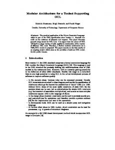
2. Design system to support modular design 2.1 The modular design in a product design The interface of the modularized product means the functional and structural joints between modules to realize a product. Therefore, it is very important for the design of a product to fully take the interface between modules into consideration. It becomes difficult to design a modular interface since the number and the associated information on a component become huge in a product design when a design progresses to a down-stream stage. If a modularization is considered step by step from the upper stage of a product design, examination of the modularization in the suitable range at each design stage is realized, and it can be expected to examine the whole modularization. Moreover, the optimal design of a product is very difficult with thinking of the combination of a desirable module may not necessarily guarantee interfaces, when a product design is carried out by the combination of the existing module. By the way, on the assumption that the modular design is dividing the product currently generated with consistency of the joint information between product’s parts/sub-systems, by selecting interfaces from the designed joints between the modules, a module can be defined with the adjustment of an interface. Moreover, a designer can examine the product information that is easy to carry out a modularization, the specification of an interface, etc. by feeding back of the examination result of the interface in a modularization to a product design. The cycle shown in Figure 1 is the basic sequence of a modular design proposed in this research, and this
Product Design Phase
Genarating interface information Design the detailed and actual part of an interface
Product Design Re-design of interface information
Evaluate Module
Consideration the connection nature of an interface Reference of the information on an interface
A A
D
A1
D
A2 B1
abstract,conceptual
C1
B
C
D
To Detail Meeting The Specifications
To Detail
Detailed Design Detailed Informations
Detailed Estimation of Relations
Materialization of Modularization Estimate Module Plans with Detailed Information
B2
D1 D2
concrete,detailed A
To Detail
abstractly. The instance of that information is a location or a type of joint. And when design goes to a downstream stage, detailed shape of parts are defined, and detailed shape, direction of joints are designed.
C B
C
B
Estimation of Module Specifications Decide The Specifications of Relation
Figure 3. Two characteristic phases for a modular design
Figure 1. The design cycle of a modular design
P ro du c t In fo rm atio n
Estimate The Specifications of Relations
Abstract Design
Relation (Function-Function) Relation (Entitiy-Entity) Relation (Function-Entity)
Modular Design
Module Design Phase
A1 A2 C1 D1 D2 B1 B2
Figure 2. Detailing product information step by step research considers support of the modular design carried out stepwise according to advance of a product design.
2.2 Interface information In a modular design, the guarantee of interface between modules is very important. Therefore, it is necessary to think carefully about the interface information that can manage the interface of the modularized product. Interface information can be classified into functional one and structural one from a view of a design and evaluation purpose [2]. Functional-Interface Information, Functional-interface has information on the flow of material, energy, and signal, and the means, mechanism and direction of transmission. At an upstream design stage, it is an abstract and intentional one such as “transmission of electric energy”, and when a product design progresses to a downstream stage, its information becomes detailed and concrete one such as “transmission of 100-watt electric energy by cable”. Structural-Interface Information, Structural-interface has information on the specification of a joint, such as a type and a shape of joint. At an upstream stage, the layout of parts is defined, but a shape of parts is designed
We expect that the integrated management of interface information enable to realize a modular design with consideration to the evaluation module. Moreover, it is expected that a designer can think about the specification in an appropriate structure of modules and influence of an interface on a design element.
2.3 Stepwise detailing modular design In an actual design, the product information is generated in detail and specified stage by stage (Figure 2). At an upstream design stage, an outline of design information on product configuration element and those interfaces are generated, and then that information is specified at a downstream design stage. If the module can be positively considered by each design phase, the component by which the modular design is considered and the specification of interface information can be considered at stages. In this research, an outline of modular design at an upstream stage is called “Consideration to the module specification”, and a detailed modular design at a downstream is called “Materialization of the modularization”(Figure 3). We develop the design support system that manages product information from an upstream to a downstream to specify product information. In this system, a modular design and a product design are considered mutually, and product and module information are generated and specified hierarchically (Figure 4).
2.4 Generating module plans and evaluation The graph model of a product, which represents the product element and joint as nodes and links respectively, is used as a model for considering and evaluating assembly-ness and disassembly-ness. In this research,
CD
A
C
A
C
B
D
B
D
change design plan (simplify interfaces)
B
CD
B
CD
compare A
modularization
A
3. Evaluation of module plans
A
modularization
A B
A
C
A
B
D
B
C D
B
CD
(A) Plan of Module Specifications A B
A1 A2
C D
A
A B
B1 B2
C B
CD A1
deveide to submodules
D
A2
C1
devide to submodules
B1
simplificasion of interfaces
D1 C D2
D1 B2
D2
(B) Matrialize Module Plan
Figure 4. Modules are planed step by step Generation of Module Plan by Cut-Set
A
C
B
D
Input The Designer's Intention Don't separate here
Module Plans
Module Plans
Figure 5. Generating module plans by cut-set from product’s graph authors introduce one graph model of a product, which can manage the information on the interface explicitly, and propose a modular design environment by which a designer can design and evaluate modules with mainly the module’s interface. In this graph, a modular design can be substituted for the problem how to get a cut-set from this graph, because the candidate module plans are generated as the sub-graph by cut-set calculation on the graph theory (Figure 5). The calculated cut-set corresponds to the interface between modules, which is an important part where the product function and structure are guaranteed, furthermore it is regarded as a target of actual job for assembly and disassembly through the life cycle of a product. Then, interface information between module components is used to judge the quality of modules in a modular design.
3.1 Viewpoint of product’s life cycle There are two loops at the life cycle of a product. One is a closed-loop type of “production–use–disposal” of a product, and another is an open-loop type including “recycle/reuse” of parts or module. At the defining an evaluation index of the life cycle cost of the modular designed product, the cost of assembly and disassembly (decomposition) through the product’s life cycle is evaluated in a closed-loop. And furthermore, the recycle / reuse cost of a module is evaluated in an open-loop. Thus, the evaluation item taking account of the product’s life cycle can be arranged as follows; - The minimization of performance for an assembly and a disassembly: Considering a position and a method of a joint to enable easy assembly and disassembly. - The minimization of frequency for an assembly and a disassembly: Making a module by grouping parts with the longevity of the period. - The maximization of value of recyclable and reusable module: Evaluating the value of the functional module by value analysis (VA), and design the high valued module to enable recycle and reuse effectively.
3.2 Evaluation from viewpoint of assembly and disassembly This research pays attention on the product components configuration, and evaluates the interfaces of modules. The specification of the interface and the separating/dividing method are related deeply to the evaluation. This research introduces an evaluation technique that is referred to DAC3 that is developed in Sony [3] and can measure the cost of assembly and disassembly.
3.3 Evaluation from viewpoint of product’s life If the life is described in each product element, we can calculate the standard deviation of the longevity of each product element. By this evaluation, we can design the combination of the product element for composing the module.
3.4 Evaluation from viewpoint of product function We estimate and evaluate the value of module function using the graph model of the product with information on
its function. The value of a module is estimated by a following equation; V=F/C, where V is value of a module, F is a estimated current cost of module’s function. C is an objective cost of module’s function. It is the lowest cost that is necessary to realize the required function to the module [4]. The modular designer distributes a current cost of each module with considering the contribution to a product’s function of each module’s function, and decides the objective cost by the comparison with other functions.
3.5 Overall evaluation and selection a satisfied module plan In a modular design, it is necessary to solve the problem “Difficulty of optimization the functional performance, the cost, weight and etc. of a product due to a considering the module” and “Difficulty of the development of the product variation due to the guarantee of the module interface”. It is important to make the design environment where a designer can feel free to think about the trade-off of the modularization. In general, it is hard to generate a good module plan overall with the satisfaction of all demands, because of there are various aspects for evaluation of module plans. Design Phase
Modularization Phase
START
Generate Abstract Module Plans
Abstract Function Design
Assembly/ Disassembly
Product Function
Abstract Entity Design
Product Life
Relation between Entities
Total Estimation Choose The Best Plan
Relation between Function And Entity No
Input The Weight of Each Viewpoint
Is It A Good Plan?
Authors have been developing the system to support of a top down oriented product design. In this research, we apply this system to a modular design. This chapter shows the feature and outline of the modular design support system. Figure 5 shows the flow of the modular design and evaluation according to the product design.
4.1 The Information model for description products The proposed design system expresses product information by “Product function”, “Entity”, and those “Relation”, and three information layers, “Function Layer”, “Entity Layer” and “Attribute Layer” are defined (Figure 6). Using these three layers, a designer can generate and evaluate information on a product step by step (Figure 6(A1)) [5]. Product Function: This function is defined to meet the required specification of a product. This is represented as a function node, and connected with others. This node are linked to “Entity node” that represents the entity corresponding to this function.
Yes
Product Specification And Module Specification Detail Function Design
Generate Detail Module Plans
Detail Function Detail Relation between Functions
Entity's Shape Connect's Length/Direction
4. Development of modular design support system
Estimate form The Viewpoint of...
Function Stracture Relation between Functions
Detail Entity Design
The degree of importance of the designer’s evaluation for a module from each viewpoint described to the abovementioned paragraph is different. In this research, we assume that designers want to evaluate overall based on their degree, and they want to select own module plan. So, the degree of importance of each viewpoint is set as a ratio for an overall evaluation according to designer's degree of importance. Therefore, all the module plans satisfy the designer’s intention as much as possible is generated in this research.
Estimate form The Viewpoint of... Product Function
Relation between Function And Entity
Assembly/ Disassembly
Product Life
Total Estimation Choose The Best Plan Is It A Good Plan?
No
Yes
Detail Product Design Plan And Module Plan END
Figure 5. Flow of a product design and modular design
Entity and Attribute: “Entity” is an informational frame for the product’s sub-system, element or parts. “Entity” has relations (part-of, association and etc.) and “Attribute” to input and store actual product data. “Attribute” is represented as a node in an attribute layer, and has constrains that are represented as links. Relation: There is a relation of a lot of kinds. They are classified as follows; - Relation between functions: They are functional relations. These relations shows flows of energy, material, and signal, etc.. - Relation between entities: They are physical relations between entities. - Relation between function and entity: This relation is correspondence “Function” with “Entity”.
4.2 Hierarchical network model The product functions and entities are generated the hierarchical network, according as they and their relations are generated in detail. This process of designing in detail are stored and managed as the hierarchical network in this system. Handling the network of entities carries out the modular design. In this system, entities are generated hierarchically and linked with the corresponded product function. Therefore, designers can take account of functions and up stream’s entities and check the effects of their module plan. The visualization of information structure of a product helps designers to make module plans with trial and error (Figure 6). Figure 6 (A)(B) shows the flow of the modular design, and (C) shows the design the interface and module in detail under planed module’s specifications at upper design stage.
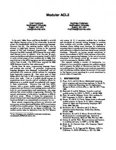
Step1: Four entities are defined to design the hair drier with considering its product functions (Figure 7(A)). A designer makes specifications for module and its interface. These interface specifications are managed in the relations between functions node. The instance of this specification is like a designer’s intention, the requirement of the joint between “heating air” and “ control hot air” in this case.
Electric Power Unit
Controller
Blower Unit
Heating Unit
Electric Power Unit
Controller
Configuration Design Blower Unit
Heating Unit
4.3 The example of a modular design
Attribute Layer
The example of a modular design for the hair drier with the prototype system, which authors developed in this research, is shown. Electric Power
Generate Hot Air Air Stream
Electric Power
Hair Dryer Hot Air
Control Hot Air
Controller
Blower Unit
Heat
Electric Power
Sub-systems network
Heating Air
Supply Electic Power
Candidate module plans network
correspondence
Hot Air
Generate Air Stream
(A) Configuration design hair dryer (define entities, relations and attributes)
10 Module Plans
never divide this interface
Heating Unit
Reduce of generation for candidate module plan
Electric Power Unit
Electric Power
correspondence correspondence
(A) Plan of Product Specification Electric Power
(B) Module Plan correspondence
Generate Hot Air Air Stream
Hot Air
Generate Air Stream
Electric Power
Hot Air
Controller
Module Plan 1
Module Plan 2
Blower Unit
Heat
Electric Power
Heating Air
Supply Electic Power
5 Module Plans
(B) Generating module plans from entities network
Hair Dryer
Control Hot Air
Sub-systems network
Heating Unit Electric Power Unit
Electric Power
Module Plans
Important Function Interface
(C) Design Product in detail and Design Interface and Module under Module specifications Module Plan 3 Motor
Controle Air Direction
Rotation Power
Switch
Generate Heat
Supply Electric Power
Functional Interface Function
1.00 0.56 0.36
Fan
Cable
re-considering interface
Module Plans by Functions
Evaluationof ModulePlan
0.6/0.2 Assemblyand Dissassembly
Convert Wind Power
Controle Electric Power
Front Grill
Heater Detailed Module Plans
Product Life
0.97 1.00 0.83
0.2/0.6 Valueof Product Function
0.72 0.84 1.00
ModulePlan#1
ModulePlan#2
ModulePlan#3
0.938/0.826
0.792/0.816
0.668/0.838
AssemblyandDisassembly/ Valueof Product Function
(C) Evaluate module plans and select satisfied plan
Phisical Interface Entity
0.2/0.2
Module
Figure 6. Multi-phased product design and modular design
Figure 7. Example of modular design (design product, make module plans and evaluate them)
Product Design
Product Design
Heating Unit Electric Power Unit
Blower Unit
Modular Design
Modular Design
Modular Design
Design detailed shape of interface
compare Figure 8. Example result of modular design at the detailed design phase Step2: Then, five module plans are generated by cut the product graph with considering a designer’s intention that is input to the function interface (Figure 7(B)). Step3: The cost of assembly and disassembly are estimated, and the standard deviation of longevity of a designed module is calculated. Figure 7(C) shows the evaluations of three module plans selected from five plans. The overall product value of each plan is estimated. The evaluate value of module plan #1 is estimates at 0.938, plan #2 is at 0.792 and plan #3 is 0.668 from the aspect of assembly and disassembly. From the aspect of product’s function value, plan #3 is the best one. Setting the weight to each evaluation respectively enables these estimations. Step4: Module plan #1 is selected as best one, the joint between “Power-supply unit” and “Heating apparatus” is deleted in order to reconsider the specification of interface. In this case, there is a little change in the evaluation result from the viewpoint of assembly, but #1 module plan is evaluated as best plan. Step5: As design proceeds, module plan #1 is specified at a down-stream design (Figure 8). Finally, the modules of the hair dryer are shown.
5. Conclusion and remarks This paper discussed and arranged the modular design from the viewpoint of the modular design and introduced the product graph model for a modular design in order to develop the modular design support system. The top down
oriented design concept is applied the modular design and importance of interface and joint information is discussed. The design model, by which the top down oriented modular design is carried out step by step, is proposed based on this arrangement. To realize top down oriented managing and generating information in detail, the hierarchical network model of “Product Functions”, “Entity” and “Attribute” are proposed. Using this network, this paper shows that the modular design can be carried out with guaranteeing the correspondence in the interface. In the future, we have to arrange the consideration item of the modular design that uses more detailed information than the shape etc. of entity. And furthermore, we plan to advance the consideration to overall support of the modular design from the upstream to the downstream.
6. References [1] Yasushi Umeda: State and Perspective of Modular Design and Manufacturing, Journal of the Japan Society for Precision Engineering, 2000.7. Vol.66 [2] G.Pahl and W.Beitz: Engineering Design –a systematic approach (Japanese edition), Baifuu-Kan, 1995 [3] Official site of Value Engineering organization, http://www. sjve.org/ [4] Yasuyuki Yamagiwa: Design for Assembly and disassembly to realize Life cycle design (in Japanese), Kogyo-chyosa-kai, 1997 [5] N.P.Suh: The Principles of Design (Japanese edition), Asakura-shyoten, 1992