Abstract â With the improvement of soft magnetic composite. (SMC) material, electric machine design is no longer limited to the traditional iron lamination ...
Research Report
2005-30 Modular Permanent Magnet Machine Based on Soft Magnetic Composite
W. Ouyang*, S. Huang**, A. Good***, T. A. Lipo*
*Department of Electrical and Computer Engineering University of Wisconsin-Madison 1415 Engineering Drive Madison, WI 53706
**Department of Automation Shanghai University Shanghai, 200072, P.R.China
*** Burgess-Norton Mfg.Co. 737 Peyton Street, Geneva, IL, 60134
Work performed at WEMPEC sponsored by CPES.
isconsin lectric achines & ower lectronics onsortium
University of Wisconsin-Madison College of Engineering Wisconsin Power Electronics Research Center 2559D Engineering Hall 1415 Engineering Drive Madison, WI 53706-1691 © 2005 Confidential
Modular Permanent Magnet Machine Based on Soft Magnetic Composite Wen Ouyang*,
Surong Huang**,
*Department of Electrical and Computer Engineering University of Wisconsin-Madison 1415 Engineering Drive Madison, WI 53706
Anne Good***,
**Department of Automation Shanghai University Shanghai, 200072, P.R.China
Abstract — With the improvement of soft magnetic composite (SMC) material, electric machine design is no longer limited to the traditional iron lamination technology. The single extrusion fabrication process of the SMC material simplifies construction of machine armature core. Moreover, the isotropic material property can be exploited for various machine structure design, compared with the 2D flux distribution of typical iron laminations. In this paper, a drive system based on a novel multi phase modular permanent magnet machine is proposed. The concentric winding structure simplifies the stator structure with the benefit of less end winding loss, which also offers the potential of fault tolerant capability. The performance of the drive system is analyzed and discussed with the simulation results provided.
T.A. Lipo* *** Burgess-Norton Mfg.Co. 737 Peyton Street, Geneva, IL, 60134
at the cost of air-gap length adjustment and current compensation for the starting and pulsating torque. For the multiphase design, a five phase drive system is proposed with less torque ripple and potential for the phase fault operation capability, but at the cost of significant increase number of switching devices in the drive circuit.
Keywords — Soft Magnetic Composite, Permanent Magnet (PM), Concentric Windings, Single Phase, Multiple Phase, Fault Tolerant
I.
INTRODUCTION
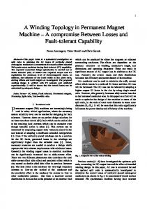
The emergence of soft magnetic composite material has greatly changed the nature of the electrical machine construction process. The possibility of a “one-punch” module reduces the work effort in lamination and stacking. Less copper loss can be achieved with the concentric winding design due to the shorter end windings for the pole piece modules.[1] The progressive improvement of soft magnetic composite (SMC) material property as illustrated in Figure 1. The isotropic property to create a 3D magnetic circuit creates possibilities for various novel electric machine designs. Some prototypes based on SMC have been reported[2-7], with[1] illustrating typical machine designs of surface permanent magnet motor, and [8] small induction motors. In this paper, novel single phase and multiphase permanent magnet drive system based on SMC modules are proposed and compared. The machine stator is assembled by independent pole pieces fabricated from the SMC material, with each pole piece mounted by an independent concentric phase winding, which also simplifies the winding efforts in machine fabrication. The rotor structure can be designed with surface permanent magnet (SPM) or internal permanent magnet (IPM) for different application requirement. For the single phase design, the machine winding achieves the maximum winding factor and minimum switching devices
Fig. 1: Magnetic property of SMC
II.
MACHINE STRUCTURE
In order to compare the effective usage of machine material, the winding factor Kw is typically defined as in [9]. A higher winding factor means higher utilization of the stator module, which includes stator winding and stator iron volume for the energy conversion, thus higher power density when the other factors are same. The general expression of Kwh with consideration of harmonic order h is expressed as:
K wh = K ph K dh K χh K sh
(1)
Kph, Kdh, Kxh, and Ksh are factors for pitch, distribution, slot opening, and skew. For the surface PM machine discussed in this paper, the distribution, skew and slot opening factors are unity due to the concentric winding, non-skew rotor structure and relative small slot opening design. Thus, the winding factor will be virtually determined by the pole pitch factor, which is generally defined as (2) [9]:
K ph = sin(
hW π hπ ) ⋅ sin( ) τp 2 2
(2)
The quantity W denotes the concentric winding span, and τp is the pole pitch. For the fundamental component, the
maximum winding factor is achieved when winding span is equal to the pole pitch, which leads to the single phase machine concept as illustrated in Figure 2. The square wave of back EMF also suggests the square waveform of current supply to achieve the maximum power density. N
S
A
ψ A
ψm
N
B
S
C
waveform and the resulting machine torque are provided in Figure 5 for comparison.
N
D EMF
π
θ
B
Fig. 4: Simulation of square wave current supply and machine torque
Fig. 2: Single phase surface PM machine concept
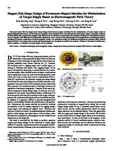
However, the intrinsic starting problems of the single phase PM motor make it necessary to apply some variation on the stator teeth shape [10]. One of the suggested techniques is to create a tapered air-gap length by shaping the tooth tip depth. By making use of the cogging torque generated by the asymmetric reluctance centers around the tooth axis, the motor can pass the zero torque production point at the cost of flexibility in rotation direction. Figure 3 gives an example design based on the single phase machine concept with tapered stator teeth and the corresponding cogging torque property. The machine stator is an assembly of eight pole pieces fabricated from SMC material or even steel laminations. The air-gap length between rotor rare earth PMs and stator poles is varied from 0.7 mm to 1.3 mm.
Fig. 3: Single phase machine example design and the cogging torque property
When the PM axes are aligned with the stator pole piece axes, which corresponds to the rotor position of 22.5 degrees, the machine still develops significant cogging torque to ride over the point with difficulty in the active torque production, where is usually the rotor position point for current commutation. With a rated square waveform current supply, the machine total torque property is simulated as shown in Figure 4. Although the average torque is significantly higher than the rated torque of a typical 3 hp induction machine (GE-5K182BC218A) at 1755rpm for the same effective machine volume, the machine torque fluctuations and the corresponding noise and vibration problems reduce its scope of application. By pushing limit of the winding factor, the intrinsic pulsation problem that comes with this machine structure can be compensated by the active control on the current supply [11]. The compensating current
Fig. 5: Simulation of current compensation and machine torque
Although the machine torque can be improved by current compensation, the torque curve contains a sag point where the machine stator current is in the commutation process. By proper design of the machine pole shape, the torque value at this sag position can still be enhanced, but this necessity depends on the application requirement. In most cases, efforts are usually focused on the reduction of cogging torque. While in this case, the cogging torque helps the operation of machine. The current compensation also increases the stress on the switching devices due to the maximum value and the significant harmonic components, which also directly impacts the health of the capacitors on the DC bus. Moreover, due to the pulsating MMF when the machine is operated in single phase manner, the synchronism of the rotor and the excitation phase angle is a concern. The information on rotor position is necessary for the properly applied current phase, with the current amplitude controlled by the feed back from current tracking devices as a common practice. A single phase machine benefits from its simple machine structure based on SMC modules. The pole piece number can be selected with flexibility for different power rating requirements. From an investigation of an example design, the SMC based modular single phase machine can be shown to achieve significant higher power density compared with the commercial induction machine. With the large scale fabrication base, the machine cost can be further reduced. The drive circuit can also be optimally implemented by only two switching devices. All these merits make it attractive for the low cost applications. However, as mentioned before, the increased complexity of current controller and the intrinsic machine torque pulsation and the corresponding noise and vibration problems may also limit its application range. Thus, the
multiphase modular machine structure is proposed and compared with the single phase machine. Due to the fact of modular structure of stator, each module can be wounded by a concentric winding separately, which not only simplifies the labor effort on windings, but also offers flexibility of multi phase number and control strategies. In Figure 6, a stator module is illustrated based on this design concept. The module further benefits from the SMC’s flexibility of 3D flux path for its extension of pole shoe and yoke sections, as discussed by other researchers. With the same total machine volume, this stator module can make full usage of the machine air-gap space, enhancing machine’s torque production.
Based on the classic energy conversion, the machine torque and speed production equals the power input from the inverter side as (6), if the resistance and other losses are neglected.
Te ⋅ ω m = [e] ⋅ [i ] T
(6)
In this study, two typical rotor structures, surface permanent magnet (SPM) and internal permanent magnet (IPM), are discussed, as these two typical machine topologies illustrated in Figure 8. The SPM machines are widely used in industry applications for its low cost and high performance, but with the difficulties in the expended speed operation for its limited field weakening capability, due to the fact the flux from the PMs cannot be turned off and the current capability limited by the supply. However, the IPM machine exhibits impressive field weakening capability for the relatively higher machine inductance due to the less effective air-gap length.
Fig. 6: Stator module concept
In Figure 7, a five phase machine concept is illustrated based on the modular machine structure. The theoretical flux linkage and back EMF curves are also depicted for two of the phases, with π/5 electrical angle shift between phases. The fundamental winding factor 0.951 can be directly obtained from (2). N
S
A
ψ
ψm
N
B
π 5
S
C
N
D
S
E
4π 5
EMF
θ
A
B
Fig. 7: Six pole five phase surface PM machine concept
Although the winding factor is not as high as the full pitch single phase machine suggested before, the machine can be operated more easily with acceptable power density performance. (3) ~ (6) describe the machine’s governing equations of general operation.
[v ] = [e] + [r ][i ] + d [λ ] dt
(3)
where v, e, i, λ denotes the vector of phase terminal voltage, back EMF (emf), current, and flux linkage.
[λ ] = [L] ⋅ [i ] L11 L 21 [ L] = L31 L41 L51
L12 L22 L32 L42 L52
L13 L23 L33 L43 L53
(4) L14 L24 L34 L44 L54
L15 L25 L35 L45 L55
(5)
(a) (b) Fig. 8: Six pole five phase machine concept. (a) SPM. (b) IPM
For the SPM rotor design as illustrated in Figure 8, the inductance matrix L exhibits low coupling between phases due to the low mutual inductance, which benefits dealing with phase fault operation. This typical design leads to the L matrix (mH) as described in (7) simulated by software package Maxwell. On the diagonal of the matrix L in (7), the self inductance exhibits quite similar values due to the large air gap taken by the PMs. While for the off-diagonal terms, the mutual inductances are relatively coupled stronger with the adjacent phase windings for the shorter flux path, although this kind of coupling is still weak with the coupling coefficient of 0.236 and 0.174 for the adjacent and non-adjacent phase coupling. 7.89 1.89 [ LSPM ] = 1.42 1.45 1.97
1.89 8.13 2.09 1.50 1.46
1.42 2.09 8.42 2.14 1.59
1.45 1.50 2.14 8.48 2.22
1.97 1.46 1.59 2.22 8.47
(7)
With an internal permanent magnet design for the rotor structure, the effective air-gap length could be reduced significantly, resulting in a relatively higher machine inductance matrix as shown in (8). It can be observed that the self-inductances of the IPM rotor design are significantly increased. Moreover, the self inductance varies noticeably due to the d-q axis effect, which can be neglected in the SPM rotor structure. The d-axis inductance Lq = 26.22mH, with Ld =
18.11mH for this typical design. The adjacent phase coupling is quite similar with SPM for the coupling coefficient 0.266, although the inductance value is nearly tripled. The coupling between the non-adjacent phases is further reduced to around 0.164. 18.11 5.18 3.41 3.28 5.20 5.18 21.01 6.71 3.90 3.98 [ LIPM ] = 3.41 6.71 23.97 8.75 3.82 3.28 3.90 8.75 24.71 7.42 5.20 3.98 3.82 7.42 21.66
(8)
As discussed before, it is difficult to operate SPM machine in the extended speed range due to the limited filed weakening capability of this machine due to the limited controllability of flux which depends on the inductance and current product L·i. With an IPM design, the higher inductance makes it feasible to obtain an extended speed operation in field weakening range. Moreover, the lower air gap flux distribution favors IPM machine for in the high speed range as shown in Figure 9. In these two typical SPM and IPM rotor designs, rare earth (NdFeB) is used for the simulation. The thickness of PMs in the SPM design varies from 3.5mm to 6mm, while for IPM, 3mm PMs are inserted into the slots. The average air gap flux density per pole of IPM design is nearly halved compared with the SPM design. Due to the existence of saturated bridges on the rotor side structure, significant flux bypassed the main flux path as purely leakage. To design an IPM rotor with specified d-q axis reactance under wide range operation is still a challenging task for the variable load conditions and corresponding saturation level. The saturation bridges are designed with considerations for both electromagnetic and mechanical stresses, especially when the machine is operated in the high speed range.
by the independent switching devices, with the option of mounting control module with the machine module at acceptable cost. In normal operation, the machine’s square wave current is in phase with the back EMF. In case of phase winding failure, a compensation implemented by control strategy helps to maintain the machine torque. Most of the phase faults are directly related with the winding failure, i.e., open circuit and short circuit. Open circuit is quite common for the terminal connection failure, and also, the switching device failure. In Figure 10, the five-phase SPM machine with different open circuit cases are simulated. Generally, the average torque is directly proportional to the phase number in service with the same control strategy assumed for the normal operation. It is a common practice to boost the torque loss by applying compensating current in the normal phases.
Fig.10: Square wave phase current and machine torque under various open circuit failures Fig.9: Air gap radial flux distribution for SPM and IPM
One of the main merits of this modular machine structure is its fault tolerant capability and easy replacement of modules. The concentric winding is wound on each stator SMC module, resulting in an independent control unit with the feature of replacement in case of unit failure. Each unit is also controlled
However, when the winding failure is short circuited, which is usually related with the insulation defect, it is still a tough task to mitigate the failure for the huge current circulating in the shorted winding. With the IPM design, it is possible make use of the specifically injected current of the normal phase windings to reduce the flux linkage of the shorted
winding. Thus, the failure could be tolerated and the machine can still be operated under limited conditions. III.
CONCLUSION
In this paper, a novel modular PM machine with fault tolerant capability is discussed. The single phase design can make full usage of the machine material for its highest winding factor, but it is vulnerable to starting problems which cannot be avoided by normal machine design. The machine can be operated with a trade-off between specially designed air-gap length and complexity of the control circuit. Thus, the multi-phase modular concept is proposed for the applications require fault tolerant capability with comparable power density. A five phase modular machine with SPM and IPM rotor structure is studied. From the preliminary simulation results, 5 phase modular machine exhibits satisfactory torque capability both in normal operation compared with a typical 3 HP induction machine and under a fault condition with one or two phase leg loss. The prototype machine is under construction. The testing results will be reported in a future paper.
APPENDIX 5 phase SPM machine parameters Parameters
IM (GE/3HP)
5 Phase SPM Motor
OD
190mm
120mm
ID
120mm
72mm
RPM
1750
1800
Machine Length
70mm(iron)/150mm(full)
140mm
Torque (T)
11.87Nm
13.26Nm
Effective Volume
-3
3
1.5834×10⁻³ m3
4.2529×10 m
Torque Density
2.791×10 Nm/m
8.374×10³ Nm/m3
Cogging Torque
0
3.01% of rated
Torque Density Ratio
3
3
5 phase PM / IM = 3.0
REFERENCE [1]
L. O. Hultman and A. G. Jack, "Soft magnetic composites-materials and applications," 2003. IEMDC'03, vol.1, pp: 516, June 2003. [2] A. Jack, "Experience with using soft magnetic composites for electrical machines" , New Magnetic Materials - Bonded Iron, Lamination Steels, Sintered Iron and Permanent Magnets, IEE Colloquium on 28, May 1998 pp:3/1 - 3/4. [3] A. G. Jack, B. C. Mecrow, C. P. Maddison, and N. A. Wahab, "Claw pole armature permanent magnet machines exploiting soft iron powder metallurgy," Electric Machines and Drives Conference Record, 1997, IEEE International, pp.18-21, May 1997. [4] A. G. Jack, B. C. Mecrow, P. G. Dickinson, D. Stephenson, J. S. Burdess, N. Fawcett, and J. T. Evans, "Permanent-magnet machines with powdered iron cores and prepressed windings," Industry Applications, IEEE Transactions on, vol. 36, pp. 1077, 2000. [5] Y. G. Guo, J. G. Zhu, P. A. Watterson, and W. Wu, "Comparative study of 3D flux electrical machines with soft magnetic composite cores", Industry Applications Conference, 2002. 37th IAS Annual Meeting, pp.1147 vol.2 [6] B. C. Mecrow, A. G. Jack, D. J. Atkinson, P. G. Dickinson, and S. Swaddle, "High torque machines for power hand tool applications”,
Power Electronics, Machines and Drives, 2002. International Conference, June 2002, pp.644 [7] J. Cros and P. Viarouge, "New structures of polyphase claw-pole machines", Industry Applications Conference, 37th IAS Annual Meeting, Oct. 2002, pp.2267, vol.4 [8] R. Qu, G. B. Kliman, and R. Carl, "Split-phase claw-pole induction machines with soft magnetic composite cores", Industry Applications Conference, 39th IAS Annual Meeting, Oct. 2004, pp.2514, vol.4 [9] T.A.Lipo, “Introduction to AC Machine Design”, (book), University of Wisconsin, 2004. [10] S. Bentouati, Z. Q. Zhu, and D. Howe, "Influence of design parameters on the starting torque of a single-phase PM brushless DC motor," Magnetics, IEEE Transactions on, vol. 36, pp. 3533, 2000. [11] T. M. Jahns, Wen L. Soong, “Pulsating Torque Minimization Techniques for Permanent Magnet AC Motor Drives – A Revew”, Industrial Electronics, IEEE Transactions on, vol. 43, pp. 321, April, 1996. [12] B.A. Welchko, J. Wai, T.M. Jahns, T.A. ;Lipo,, “Magnet flux control of interior PM machine drives for improved response to short-circuit faults”, IAS 2004, IEEE conference, Volume 1, pp.3. 2004.