for the Intel IXP1200 network processor. StepNP [14] is a design framework for network processors that uses Click for specifying the application. In the CLIFF [9] ...
C. Sauer, M. Gries, S. Sonntag: Modular Reference Implementation of an IP-DSLAM, 10th IEEE Symposium on Computers and Communications (ISCC), June 2005
Modular Reference Implementation of an IP-DSLAM Christian Sauer, Matthias Gries, S¨oren Sonntag Infineon Technologies, Corporate Research, Munich, Germany {Christian.Sauer|Matthias.Gries|Soeren.Sonntag}@infineon.com Abstract We describe a modular reference implementation of an IPbased DSL access multiplexer (DSLAM). We identify deployment trends and primary tasks a future DSLAM has to offer. The implementation is representative of applications in access networks and indicative of real-world performance. To accomplish these goals our tool flow CRACC takes a modular application description and generates code for embedded processors that can easily be ported to different platforms. The derived implementation serves as a benchmark for DSLAM systems. It therefore allows the comparison of different architectures, partitioning, and mapping decisions. In addition to a full system benchmark, our reference implementation is a functionally correct realization with defined evaluation environment, traffic sources, and load scenarios. We present evaluation results of our DSLAM implementation on several embedded processors.
1. Introduction DSLAMs connect individual customers with the broadband service provider network. Today’s DSLAMs can become quite large systems by aggregating several thousands of subscriber lines. They are built modularly out of different line cards, a backplane, and at least one trunk card, see Figure 1. Figure 2 highlights our future outlook on aggregation and transport technologies, where most of the traditional equipment has become obsolete. Narrowband switches and ATM switches have completely disappeared. Former broadband remote access server (BRAS) functions have become partly obsolete, partly distributed. The IP-DSLAM now represents the central access point for all narrow- and broadband services. In order to build such systems, well defined traffic scenarios and application benchmarks are required to explore design trade-offs. These design trade-offs are not bound to the architecture of a line or trunk card, but affect the functional partition between these cards, too. However, no system-level benchmarks have been defined so far that specify both comparable and representative DSLAM usage scenarios. Existing benchmarks often focus on function kernels only, e. g. packet forwarding, MPLS, or IPSec. Although most of these kernels represent typical computa-
tional loads they often cannot be used off-the-shelf for a particular application. This is why we recognize the need for a reference implementation of a complete DSLAM system to first enable design space exploration and furthermore simplify the programming of the resulting system. This process is particularly eased if the benchmark application can be derived in a modular way for evaluating different partitioning and mapping decisions. Such a reference implementation has to capture the following trends in access networks: • ATM is slowly vanishing out of the core and access networks and replaced by Ethernet based solutions. Our reference therefore must support Ethernet as well as ATM as layer-2 protocols. • Addressing the trend to use Ethernet protocol even for the first/last mile, we further require our DSLAM to support Quality-of-Service (QoS) features, including metering, policing, and scheduling [6], based on Internet Protocol. IP eventually will be the only remaining layer-3 protocol and used end-to-end. • Although IPv4 currently is the dominating protocol, IPv6 needs to be supported in the near future [4]. • Emerging applications, such as video broadcasting, can be implemented efficiently if a DSLAM system supports multicast traffic in downstream direction. DSLAM Architecture xDSL
Line card
xDSL
Line card
xDSL
Line card
Trunk card Back plane
ISP
Service card DSLAM Control
Upstream traffic Downstream traffic
Figure 1. DSLAM system architecture. In addition to the network trends above, we observe the trend to deploy Ethernet even within a DSLAM system since the switched backplane can be built from cost-efficient commodity products. Due to the variety in protocols a modular, executable, comparable, and representative application development framework is mandatory so that customizations of, e. g., firmware can quickly be achieved. In this
paper we introduce an application description of a future IPbased DSLAM that is modular, executable, and provides an efficient path to implementation. The specification is based on Click [8] and thus also provides a natural documentation of the functionality. A case study underpins the usefulness of our approach for application-driven design space exploration. Customer-Premises Equipment (CPE)
CPE CPE CPE
xDSL
Internet Ethernet
Multiple Services provider network (voice, video, data)
or ATM Router
IPIP-DSLAM Digital Subscriber Line Access Multiplexer
Figure 2. IP-DSLAM deployment scenario. This paper is structured as follows. In the following section, we describe line and trunk card configurations, as well as typical traffic mixes generated by customers. Section 3 continues with specifying a functional application model of an IP-DSLAM. Section 4 presents the results of profiling the DSLAM application on different embedded core architectures. In Section 5 we discuss our results with respect to related work. Section 6 concludes this paper.
2. Definition of DSLAM Scenarios Describing and implementing the functionality of an IPDSLAM is not a straightforward task. Already at the application level, the designer needs to make numerous choices, e. g., which traffic classes and protocols to support. Keeping in mind that we are looking for a reference implementation that can be used for design space exploration, we describe the various design and configuration axes for such a reference implementation in three categories. • Function – Functional parameters vary the functionality of the DSLAM itself. • Architecture – Architectural parameters determine, for instance, the total number of subscriber lines. • Environment – These parameters define traffic assumptions for the IP-DSLAM and the surrounding testbench. Next, we describe line and trunk card configurations and define typical traffic scenarios based on existing and future Internet applications. We summarize the relevant parameter sets for system configuration at the end of this section. 2.1. Architectural Assumptions A DSLAM internally consists of up to 32 line cards, where each line card aggregates up to 72 customer xDSL lines (cf. Sec. 2.2). The number of line cards is usually bounded by
physical dimensions of the DSLAM and the regional distribution of customers. The number of ports per line card is determined by the type of multi-pair binder cables used for distribution. Traffic from the line cards is bundled by one to two trunk cards towards the service provider. The internal multiplexer/demultiplexer cascade of our DSLAM between line and trunk cards is realized using one or multiple Ethernet switch(es). These highvolume standard parts enable a cost-efficient system design. Packets that cross the backplane require Ethernet framing/deframing functionality. Per-packet state needs to be sent along with the frame using header fields and/or a conveyance header. The Ethernet switch can potentially be a bottleneck of the system. We therefore require policing on the line cards to prevent the switch from being flooded by bursts. Short bursts should be queued rather than dropped. Different partitions of functionality between line and trunk cards are possible and motivated by several reasons: • The regional distribution of customers may lead to underused line cards so that centralized processing on the trunk card leads to better resource utilization. • High per-packet and customer-specific processing favors a de-centralized implementation on the line cards, where computations can be done at lower traffic rates. • A partitioning can be chosen so that line and trunk card architectures can be based on the same platform. • The costs of the Ethernet backplane might be a dominant factor so that most of the processing (including drop decisions) should be done before traffic is switched through the backplane, thus favoring a distributed version that distributes the processing among line and trunk cards. • The functionality can be reduced if we can rely on certain assumptions, e. g., that the customer premises equipment can be configured by the ISP. In this case, traffic is marked and policed by the trusted customer. 2.2. Traffic Aggregation Since the line cards are at the network edge to the customer, they are often dimensioned for the worst-case. In order to avoid a customer’s non-conforming traffic to affect other customers, a line card should be able to handle the worst-case of small packets at peak rates. Table 1 gives an overview of typical line card configurations for three representative subscriber line technologies: ADSL, VDSL, and SHDSL. The upcoming ADSL2+ standard can be seen as a line technology between ADSL and VDSL and is therefore not listed. ADSL2+ supports up to double the peak bandwidth of plain ADSL within the same geographical radius. Since ISPs want to bound the maximum number of customers affected by a possible defect on one of the line cards, the maximum number of ports is typically restricted to 64 ports in Europe, whereas we also find multiple of 24 ports (up to 72) in the American market.
Table 1. Peak traffic rates, DSLAM line card. Customer line (ports per LC) ADSL (64) VDSL (16) SHDSL (64)
Peak bandwidth per port [Mbps] down up 8 52 2.3
1 6.4 2.3
Peak bandwidth per line card [Mbps] down up 512 832 148
64 103 148
Table 2. Sustainable rates, DSLAM trunk card. Customer line ADSL VDSL SHDSL
Number of active ports 320 48 512
Number of line cards 20 12 32
Sustained bandwidth down [Mbps] up [Mbps] 1280 160 1248 154 589 589
Since a DSLAM may aggregate the traffic from up to 32 line cards, a trunk card built for the worst-case needs considerably more resources than a line card. We can however exploit statistical traffic properties known from measurements of ISPs. We assume that on the average only one fourth of all customers connected to a DSLAM are online at a time, and these use only half of their peak bandwidth. That means the required sustainable rate is only one eighth of the theoretical peak rate. Table 2 shows potential working points for a trunk card, derived from the peak bandwidth of a 10 Gbps link to the ISP network. For the ADSL and VDSL cases, the maximum number of line cards is not reached. The sustainable rate can be increased by putting up to 32 line cards into a DSLAM, depending on the compute and storage resources that are available. The requirements can further be reduced if a typical traffic mix is assumed. This traffic mix is discussed next. 2.3. Traffic Mix and Setups In a future multi-service access network, QoS is a mandatory feature to protect customer traffic from other traffic and to support hard guarantees in terms of delay and loss rate. Differentiated Services (DiffServ) [3] have been introduced for this purpose. The most common scheme distinguishes three different service levels: • Expedited Forwarding (EF) – The highest service level is usually used for low-latency low-bandwidth non-reactive UDP traffic, such as voice traffic. • Assured Forwarding (AF) – AF can be subdivided into traffic classes with varying loss rate and delay properties. Typical traffic for AF is based on non-reactive UDP traffic with higher bandwidth demand, but less strict requirements on delay and loss. Examples are video-on-demand and tele-conferencing. • Best Effort (BE) – Traffic without defined QoS belongs to this class, such as TCP-based elastic Internet traffic. In order to get an idea what a realistic traffic mix is, we list common and future applications for the Internet in Table 3. Currently, a typical traffic mix contains one to three
VoIP telephone connections as EF traffic, one video-ondemand connection at 1 to 2 Mbps as AF traffic, and ftp/http traffic for BE. We assume that although the available bandwidth will grow, the relative partitioning among these traffic classes remains the same. VoIP traffic will be replaced by video phones, video-on-demand will use DVD quality, and so on. We therefore assume the following traffic mix for each customer: • The EF traffic is bound to 10 % and uses small packets (64 to 100 Byte length). • AF traffic is bound to 30 % of the available bandwidth. The average packet length is relatively large (550 Byte), since video traffic is assumed. • The remaining 60 % represent BE Internet traffic. We assume the simple Internet traffic mix (Imix [1]) that corresponds to an average IP packet length of about 340 Byte. Table 3. Internet application requirements. Application VoIP, compressed MP3 (44.1 KHz, 16 bit, stereo) MPEG2/Main Level (720 x 480) MPEG4: DivX MPEG2/HDTV Level (1440 x 1080) Application HTML page MP3 song (5 min) Panorama JPEG (8K x 1K) Photo-realistic VR model MPEG4/DivX movie (90 min)
Required bandwidth/user 9.6 Kbit/s 140 Kbit/s 6 Mbit/s 1 Mbit/s 25 Mbit/s Load time File size (at 20 Mbit/s) 200 KByte 0.1 s 5 MByte 2.5 s 3 MByte 1.5 s 300 MByte 2.5 min 700 MByte 6.0 min
The described traffic mix has an average packet length of about 260 Byte. If the DSLAM has only headers to process and is built for the traffic mix, it is safe to say that the computational requirements can be reduced to one fourth of the worst-case (64 Byte packets). We distinguish three traffic setups: The QoS traffic mix described in the preceding subsection, QoS traffic mix with multicast where part of the BE traffic is replaced by multicast traffic, and a traffic mix that adds IP errors and ICMP (network management) packets to the multicast setup. 2.4. Parameter Sets Table 4 summarizes the DSLAM configuration parameters discussed in this section. All possible combinations of these parameters define valid deployment scenarios and affect the dimensioning of the corresponding DSLAM. In the next section, the DSLAM application is described. Possible platform architectures are then evaluated in Section 4 for several parameter combinations listed in Table 4.
3. Design of an IP-DSLAM in Click We model the functionality of the IP-DSLAM in Click [8], a domain-specific framework for describing network applications. We have chosen Click for several reasons: Click
Table 4. Parameter sets for DSLAM reference implementations. Function DSL port protocol • ATM • Ethernet
IP version • •
IPv4 IPv6
Uplink protocol • ATM • Ethernet
Number of line cards 1–32
Architecture Ports per Function split line card • distributed 1–72 • centralized • decentralized
models are modular, executable, implementation independent, and capture inherent parallelism in packet flows and dependencies among elements (Click components). Click’s abstraction level and the existing extensible element library allow us to focus on application specifics during the implementation. By using Click, a functionally correct model of the application can be derived quickly. The subsequent performance optimization can focus on individual elements and the partitioning of elements onto processing cores. Our IP-DSLAM model implements the data plane only. The interface between control and data plane, however, is implemented on the data-plane side. ICMP packets targeted for the control plane are currently discarded after classification. Other data structures that are shared among data and control plane are modeled accordingly. Lookup tables, for instance, are accessed read-only, the management information base (MIB) is only written. 3.1. Click Characteristics Click applications are composed in a domain-specific language from elements written in C++ that can be linked by directed connections. The elements describe common computational network operations, whereas connections specify the flow of packets between elements. Packets are the only data type that can be communicated. All application state is kept local within elements. Two patterns of packet communication are distinguished in Click: Push and pull. Push communication is initiated by a source element and models the arrival of packets at the system. Pull communication is initiated by a sink and models space that becomes available in an outbound resource. Figure 3 shows a Click example using a common graphical syntax to represent the interaction of elements. Packets are inserted by the FromDevice element into the system (push outputs [black]). The packets are then fed into a packet classifier. This element forwards a packet to one of its output ports depending on, e. g., filtering header fields. Two outputs are connected to queues. In Click, queues are explicit elements that have push inputs and pull outputs (white). Thus, the packet scheduler can pull packets out of the queue at its own rate removing them from the system. Packet generation for evaluating our IP-DSLAM is done in a modular and extensible manner. We implemented a number of new click elements that can be used to compose layered packet sources. Such a source first generates a chunk of data which is encapsulated repeatedly depend-
Environment Packet length
Traffic setup
Port throughput
QoS traffic partition • Traffic mix
•
QoS Multicast • ICMP/errors
ADSL/VDSL (asymmetric) • SHDSL (symmetric)
•
•
•
Queue0
FromDevice
Classifier
Queue1
Scheduler
ToDevice
Discard
Figure 3. Click example. ing on the desired protocol stack. Multiple of these layered sources are multiplexed in order to provide the required protocol and traffic scenarios for our IP-DSLAM reference. We use Click’s paint and user annotation concepts to carry sideband information with the packet. Currently, 4 Byte are used to encode protocol type, port number on the line card, line card number, and traffic class. In upstream direction this data specifies the source, in downstream direction the destination of the packet. 3.2. General Concept Figure 4 shows the principal Click top level of the DSLAM. The DSLAM consists of the actual DSLAM function (grey compound box) and a testbench that contains traffic sources and sinks. This testbench together with the DSLAM configuration, i. e. the setup of routing tables, classifiers, and traffic rates, defines a particular environment for the DSLAM. DSL DSL0 source DSL1 source DSL1 source source n DSL DSL0 source DSL1 source DSL1 source source n
Line card 0
Crossbar channel
Line card 1
Crossbar channel Trunk card
DSL DSL0 source DSL1 source DSL1 source source n
Line card m
Upstream sink
Crossbar channel IP-DSLAM — upstream dataflow
Figure 4. DSLAM upstream top level in Click. The DSLAM function is partitioned into upstream (shown in the figure) and downstream flows, which are implemented independently since they do not interact directly at the data plane level. They can be mapped onto the same processor element. In both directions the DSLAM consists of line cards and trunk cards that implement aggregation and processing tasks. Individual connections called (crossbar-) channels connect the cards with each other. The channels are the abstraction of an Ethernet switch (or switching cascade). They provide point-to-point links with limited bandwidth.
Line cards have a number of individual DSL ports and one port to the internal crossbar. Trunk cards have a number of crossbar ports and one uplink port. This functionally correct arrangement has been chosen for ease of implementation. Real world trunk cards have only one high speed port to the crossbar instead, thus leaving the multiplex/demultiplex step to the crossbar. A DSLAM that intends to exploit the switching capabilities between line cards would have to use a refined abstraction of the Ethernet backplane. All cards have push inputs and pull outputs, and some queuing is required on the cards. The channels pull packets with constant bitrates from one card and push them into the next card, similarly to sources (push) and sinks (pull). The rates of sources, sinks, and channel elements have to be balanced for an operational model. 3.3. DSLAM Functionality The functionality of a future DSLAM can be described by a set of eleven primary tasks that are explained next. A primary task may contain several Click elements: • Ethernet encapsulation: Encapsulated IP packets that are received on an ingress port are extracted from the frame, processed, and encapsulated again to be transported over the internal backplane or to egress ports. We use Click’s EtherEncap, SetCRC32, CheckCRC32, and Strip elements for that purpose. They are encapsulated in from eth and to eth compound elements. • AAL5: AAL5 splits IP packets into a ATM cells or reassembles them, respectively. We use ATM solely as layer-2 point-to-point protocol. Our IP-DSLAM does not rely on any of ATM’s QoS features. Two Click elements IP2ATM and ATM2IP have been implemented for AAL5. • IP header check: Packets are checked as specified in RFC1812 [2]. This includes checksum and TTL/ HLIM verification. We use modified CheckIPHeader and CheckIP6Header elements. • IP source address/port verification: In upstream direction for each DSL port the source addresses are verified. An IPVerifyPort element has been implemented that uses reverse-path forwarding on the IP source address to verify the annotated port information. • 5-tuple classification/destination lookup: Based on IP source/destination addresses, protocol type, and layer-4 protocols and port numbers a classification is performed to determine traffic class and forwarding information. Click’s IPFilter and a derived IPFilterAnno are used. • Traffic policing and QoS: In downstream direction the classification result is used for traffic conditioning. In upstream direction traffic profiles derived from service-level agreements are enforced. We use Click’s BandwidthMeter for policing the connected queues. Schedulers provide the required QoS distinction.
• Multicast duplication: Multicast duplication may be performed in downstream direction in up to two stages, depending on the function split between the cards. On the trunk card stage one duplicates packets per line card; stage two on the line card duplicates packets per port. • Queuing: Traffic is queued per traffic class based on Click’s SimpleQueue. • Priority scheduling: Click provides a set of scheduling schemes, e. g. fixed priority, round robin, and deficit round robin. We currently use fixed priority (PrioSched) for our implementation. • Set DiffServ codepoint: In upstream direction, the classification result is annotated to the IP packet using the Differentiated Services (DiffServ) codepoint. This enables trusted systems further upstream to reuse the result. • Decrement TTL/HLIM: The time-to-live field (IPv4) and the hop-limit field (IPv6) are decremented before a packet leaves the system. Table 5 shows an example, how the described primary tasks can be used to implement a distributed DSLAM. In the following subsection, Click specifications for this configuration are explained in more detail. Table 5. Deployed functions in a distributed split between line (LC) and trunk card (TC). DSLAM Function Ethernet deframing or AAL5 reassembly IP header check IP source address/DSL port verification Traffic classification/Forwarding lookup Traffic policing and QoS Multicast duplication Queuing by traffic classes Priority scheduling Set DiffServ codepoint Decrement TTL/HLIM, update CRC Ethernet encap or AAL5 segmentation
LC
up TC
down TC LC
+/+ + + +/– + + + + – – +/–
+/– – – –/– – – + + + + +/+
+/+ + – +/+ – + + + – – +/–
+/– – – –/– – + (+) + – + +/+
3.4. A Reference DSLAM for Distributed Function Split Using the distributed scenario from the previous section, we now describe the corresponding Click implementation. Due to limited space we refrain from showing all possible functional partitions. Figure 5 shows the upstream packet flow. The line card shown in the figure embodies different protocol scenarios. It implements four ports that are configured for the four possible protocol combinations Ethernet/IPv4, ATM/IPv4, ATM/IPv6, and Ethernet/IPv6. To a large extent these steps are implemented per DSL port, i. e. per customer. This is natural since policing and queuing need to be done per customer anyway in order to be fair. The traffic is then aggregated into one set of QoS queues per line card. The corresponding trunk card deploys an Ethernet uplink port in the
Bandwidth meter Bandwidth meter Bandwidth meter
SetAnno (3,0) SetAnno (3,1)
a) IPv4 only Decrement IPTTL
SetAnno (3,tc-1) Queue
Bandwidth meter Bandwidth meter Bandwidth meter
Bandwidth meter Bandwidth meter Bandwidth meter
SetAnno (3,0) SetAnno (3,1)
Queue 0 Queue
SetAnno (3,tc-1)
Queue 1
SetAnno (3,0) SetAnno (3,1)
Queue tc-1
CheckPaint
Decrement IPTTL
Decrement IPv6HLIM
Queue
b) IPv4/IPv6
SetAnno (3,tc-1) Queue
Bandwidth meter Bandwidth meter Bandwidth meter
Decrement IPv6HLIM
SetAnno (3,0) SetAnno (3,1) SetAnno (3,tc-1)
c) IPv6 only Line Card Upstream
p — Number of ports tc — Number of traffic classes
Trunk Card Upstream tc — Number of traffic classes
Figure 5. Exemplary upstream line card (left) and trunk card (right) combining IPv4 and IPv6. Queue 0
Queue
Queue 1
Queue
Queue tc-1
Queue Queue 0 Queue 1
Queue
Queue tc-1
Queue 0 Queue 1
Queue
Queue tc-1
Queue
Trunk Card Downstream
Line Card Downstream
tc — Number of traffic classes n — Number of line cards
p — Number of ports
Figure 6. Exemplary downstream trunk card (left) and line card (right). example. Different IP protocol variants (a-c) are demonstrated in the figure. The cards in downstream direction are shown in Figure 6. The trunk card in downstream direction again deploys an Ethernet uplink port and supports a mixed IPv4/IPv6 scenario. In downstream direction, packet forwarding and traffic management per line card are necessary besides the usual packet verification. Additionally, multicast packets need to be handled. It should be noted that the destination lookup provides a combined record with destination line card ID and port ID, multicast group (if any), and traffic class information. In this way, only one classification step is necessary. ICMP packets addressed for the IP-DSLAM itself are filtered out of the packet stream as soon as the IP header verification has been successful. Similar to the upstream line card, the downstream line card shows all ATM/Ethernet/IPv4/IPv6 combinations. The multicast duplication is implemented in two stages to keep the internal system load as low as possible. The 2-stage approach requires only a simple traffic management scheme (two buffers per port) on the line card to ensure that traffic with higher priorities precedes the best effort multicast traffic. The QoS packet scheduling has already been performed on the trunk card. The pure Click description of an exemplary distributed DSLAM requires only 266 lines-of-code (w/o comments), representing 932 connected Click elements for four line cards, one trunk card, four ports per line card, three QoS classes per customer, and layered traffic sources and sinks.
4. DSLAM Architecture Evaluation In this section, we discuss different platform implementation alternatives of the DSLAM functionality described in the preceding section. We have modeled several functional partitions between line and trunk cards in Click and use our design flow CRACC [15] to generate code for a set of ten embedded processors, which includes the common 32-bit cores MIPS, ARM, and PowerPC. We use C-compilers and cycle-accurate simulators for the performance evaluation of different partitions. 4.1. CRACC – Click for Embedded Processors Click [8] is written in C++. Since most embedded processors can only be programmed in C, we have developed CRACC, a framework that allows us to generate C from Click descriptions. The application programmer models the functionality on any host where Click can be simulated. After a functionally correct model of the application has been derived, which can be done quickly, CRACC’s Click frontend is used to generate a netlist and the corresponding configurations for CRACC library elements. The source code can be cross-compiled and profiled on the respective embedded platform. Details on CRACC can be found in [15]. 4.2. Performance Results For this study, we evaluated different function partitions between line and trunk cards of the IP-DSLAM. We have a look at the three corner cases mentioned earlier: 1) A centralized implementation (most processing on trunk card), 2)
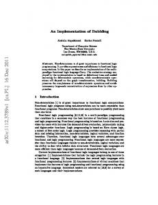
a de-centralized implementation (processing on line cards), and 3) a distributed implementation, where most of the processing is done near the ingress point of the traffic. In Figure 7, the profiling results for the three variants are shown for three 32-bit embedded cores: ARM, MIPS, and PowerPC. The results are scaled down to the number of cycles required for the processing of a single packet. For the centralized and decentralized cases, one can clearly recognize the shift of the cycle demand from trunk card to line card. The computation demand of the trunk card is asymmetric because in downstream direction a forwarding decision must be made to route traffic to the correct line card. The results for the distributed implementation reveal that some functionality of a centralized trunk card can be shifted to the line card in upstream direction. In all cases, the ARM processor has the lowest computation requirement per packet, whereas the PowerPC shows the largest. To put these results into the right perspective, we use a MIPS core running at 300 MHz as comparison basis. As described in Section 2.2, we dimension the line card for the worst-case (maximum DSL throughput per port, small packets only), while a trunk card can be built for the average case (traffic mix and statistical multiplex of customer traffic). We assume 64 ports per line card at ADSL and SHDSL line rates and 16 ports for VDSL respectively. 20 / 12 / 32 line cards per DSLAM are assumed for ADSL / VDSL / SHDSL. We list the number of required MIPS cores (running at 300 MHz) in Table 6 for our three corner cases. Table 6. Required number of MIPS cores. 300 MHz cores ADSL Line card Trunk card VDSL Line card Trunk card SHDSL Line card Trunk card
Distributed 3 6 5 5 3 3
Centralized 3 6 4 6 2 4
Decentralized 6 3 10 3 4 2
There is almost no difference between a distributed and centralized solution for asymmetric customer links. The CPU utilization decreases by 16 % on the line cards and increases by 4 % on the trunk card if a centralized organization is used. That means, although some upstream functionality of a line card can be moved to a trunk card, the upstream traffic volume is too low to affect the utilization significantly. On the other hand, for symmetrical customer lines, the line card requirements can be reduced by one core. In any case, as expected, the decentralized solution needs the most CPUs on a line card. Other factors are not discussed here but affect a particular organization, such as packet delay, memory requirements, and the dimensioning of the Ethernet backplane. We would like to point out that these elaborations can be done quickly using our tool flow [15]. The platform architecture
discussion in this paper serves as a case study to underpin the usefulness of a modular specification and implementation framework for rapid prototyping.
5. Related Work and Discussion Related work can be found in three areas: Click for application specification, benchmarking, and case studies. Click [8] is implemented on Linux using C++. Recent extensions to Click include SMP-Click [5] and NP-Click [16]. In [5], a multi-threaded Linux implementation for general-purpose PC hardware is described. In [16], Shah et al. show how Click, augmented with some abstracted architectural features, can be used as a programming model for the Intel IXP 1200 network processor. StepNP [14] is a design framework for network processors that uses Click for specifying the application. In the CLIFF [9] work, Click elements are mapped to FPGAs. We are aware of seven NP benchmarking efforts: CommBench [17], EEMBC (www.eembc.org), MiBench [7], NetBench [12], NpBench [10], NPF BWG (www.npforum.org), and Linley-Bench (www.linleygroup.com). The granularity of the benchmarks can be distinguished in micro, function, and system-level. Most of the suites define micro-level benchmarks, e. g. CRC32 and table lookup. Some suites define function-level benchmarks. The most common function is IPv4 forwarding. However, none of the approaches defines a system-level benchmark as needed in our case, including multicast, QoS, and layer-2 functionality. Publications on DSLAMs can only sparsely be found. The description of a trunk card in [13] is based on Intel IXP network processors and also elaborates on control plane aspects. The functionality on the data plane includes AAL5 and forwarding. An implementation of DiffServ on Intel’s IXP NPs is described in [11]. These implementations are programmed in assembly for the most part. Discussion. To promote reuse and wide acceptance among embedded software developers, we employ an library-based ANSI-C tool flow that uses modular Click components for specification. This is a reasonable trade-off between implementation efficiency and portability, since C is often the only abstraction above assembler that is offered for programming embedded systems. We choose Click due to its wide acceptance in the network processing domain. From our case studies we notice a large application design productivity gain from using a modular and systematic tool flow. A DSLAM scenario can be input within a day, and testing and configuration of filters and lookup tables take another few days. This enables rapid prototyping and design space exploration, whereas in plain assembly a single implementation may take months. Moreover, a performance optimization can focus on individual components, whereas in assembly often modifications to the whole code base are required.
3500
3500 ARM
MIPS
PowerPC
ARM
MIPS
3500
PowerPC
ARM
3000
3000
3000
2500
2500
2500
2000
2000
2000
1500
1500
1500
1000
1000
1000
500
500
500
0
0 Linecard upstream
Linecard downstream
Trunkcard upstream
Trunkcard downstream
MIPS
PowerPC
0
Linecard upstream
Linecard downstream
Trunkcard upstream
Trunkcard downstream
Linecard upstream
Linecard downstream
Trunkcard upstream
Trunkcard downstream
Figure 7. Centralized (L), decentralized (M), and distributed (R) DSLAM performance [cycles/packet].
6. Conclusion
References
The goal of this work is the development of a modular specification of a future DSLAM that enables the systematic evaluation of partitioning and mapping trade offs. For this purpose we have captured trends, such as QoS per customer, downstream multicast, and the prevalent use of Ethernet/IP end-to-end. We have identified eleven primary tasks that a future DSLAM has to support and developed a realistic system environment including traffic workload. Based on our findings we have restricted the design space to a set of reasonable alternatives for DSLAM implementations. Our framework CRACC [15] that we use to derive a DSLAM reference implementation on embedded processors allows the designer to specify the application with correct functionality from the very beginning. Since the Click input is used for code generation, the resulting program is indicative of real-world performance. The modularity of Click/CRACC enables a natural encapsulation of local data and processing required for certain tasks. The number of mapping and partitioning choices can thus be reduced considerably to a set of rational alternatives. We therefore promote the use of Click as a programming environment for DSLAMs. In our case study we have demonstrated how DSLAM design alternatives on different processors can be explored.
[1] Agilent Technologies. JTC 003: Mixed packet size throughput. Journal of Internet Test Methodologies, Sept. 2004. [2] F. Baker. Requirements for IP version 4 routers. RFC 1812, Internet Engineering Task Force (IETF), June 1995. [3] S. Blake, D. Black, M. Carlson, et al. An architecture for differentiated service. RFC 2475, IETF, Dec. 1998. [4] V. Cerf. On the evolution of Internet technologies. Proceedings of the IEEE, 92(9), Sept. 2004. [5] B. Chen and R. Morris. Flexible control of parallelism in a multiprocessor PC router. In USENIX, June 2001. [6] DSL Forum. DSL evolution – architecture requirements for the support of QoS-enabled IP services. TR-059, Architecture & Transport Working Group, Sept. 2003. [7] M. Guthaus, J. Ringenberg, D. Ernst, et al. MiBench: A free, commercially representative embedded benchmark suite. In 4th Workshop on Workload Characterization, Dec. 2001. [8] E. Kohler, R. Morris, B. Chen, et al. The Click modular router. ACM Trans. on Computer Systems, 18(3), Aug. 2000. [9] C. Kulkarni, G. Brebner, and G. Schelle. Mapping a domain specific language to a platform FPGA. In DAC, 2004. [10] B. Lee and L. John. NpBench; a benchmark suite for control plane and data plane applications for network processors. In Int. Conference on Computer Design (ICCD), Oct. 2003. [11] Y. Lin, Y. Lin, S. Yang, and Y. Lin. DiffServ edge routers over network processors: Implementation and evaluation. IEEE Network, July 2003. [12] G. Memik, W. Mangione-Smith, and W. Hu. NetBench: A benchmark suite for network processors. In ICCAD, 2001. [13] R. Neogi, K. Lee, K. Panesar, and J. Zhou. Design and performance of a network-processor-based intelligent DSLAM. IEEE Network, July 2003. [14] P. Paulin, C. Pilkington, and E. Bensoudane. StepNP: a system-level exploration platform for network processors. IEEE Design & Test of Computers, 19(6):17–26, Nov. 2002. [15] C. Sauer, M. Gries, and S. Sonntag. Modular domainspecific implementation and exploration framework for embedded software platforms. In DAC, 2005. [16] N. Shah, W. Plishker, and K. Keutzer. NP-Click: A programming model for the Intel IXP1200. In Network Processor Design, volume 2. Morgan Kaufmann, Nov. 2003. [17] T. Wolf and M. Franklin. CommBench – a telecommunications benchmark for network processors. In ISPASS, 2000.
Overall, our DSLAM specification in Click together with CRACC serves as a reference system-level benchmark that is representative for access networks, indicative of real-world performance, and comparable across different implementations.
7. Acknowledgments This work has been supported by the German government (BMBF), grant 01AK065A (PlaNetS). We thank J¨orgChristian Niemann and Uwe Tellermann, University of Paderborn, Germany, for their insights in profiling embedded processors.