Modular Robot System for Maintenance Tasks in ... - SAGE Journals
Recommend Documents
By discovering the relationship between interâ netware software reachability and operation expression, they converted reachability into the recursion of internetâ.
Each leg has four joints, and each joint has one degree of freedom. This arrangement of degrees of freedom is ...... Cambridge, Massachusetts: The MIT Press. 9.
The New South Wales Roads and Traffic Authority initiated the model in 1994. ... Through the performance-specified contract (PSMC) model, these problems ...
Postdoctoral Fellow, Division of Social Science, Hong Kong University of Science and Technology, Clear ... In summer 2011, Foxconn Technology Groups, one of China's largest employers, declared ..... could rarely obtain the protection from the All-Chi
One processor is never enough. Designing a robot control system as a set of processes running on a set of computers is a good way to work. It minimizes time ...
Sep 4, 2008 - Further we deploy the Hâbridge method to realize for- ward and backward movements [9]. Then combining two DC motors attached to two ...
alternative cancer treatment: D. Barry Boyd, MD, a medical oncologist who uses integrative approaches in his practice; Nicholas Gonzalez, MD, a physician in.
Cancer patients face immune system challenges pri- marily in 2 areas: (1) fighting malignancies through immune mechanisms and (2) confronting the.
Designing a Sociable Robot System for Weight Maintenance. Cory D. ... people in their daily lives and provide support for particu- ..... BMC Health Services Re-.
Relatively speaking, negative pressure adsorption has better performance on rough surface which results in leaking of the suction chamber, because generator ...
based on PID (proportional-integral-derivative) controllers and MPC (model ... can be composed of a sequence of straight lines and circle segments [7]. Thus ... Convergence to goals and reactive ... both of the low level controllers when local path-f
ËWÑzЮ is also bounded, which accordingly guarantees the uniform continuity of WÑzЮ. Therefore, by Barbalat's. Lemma, it can obtain that WÑzЮ ! 0 as t ! Ñ1, ...
a domain that has wide applicability in terms of real-world scenarios .... scribed as follows: ⢠If an utterance starts with the name of a robot, then that is the robot ...
First Approach for Guiding-Tours ... functions of a tour guide in a museum, including leading groups of ...... coming up and our next aim is to develop a method for.
Robot-assisted weight-bearing exercise for stroke patients with limited mobility. Guo Shanshan1, Yulong Wang1, Kun Wang1, Jianjun Long1,. Xing Lv1, Zhiyong ...
[philipp, hic]@nada.kth.se. â ... problems can not be treated separately for a personal robot that ... research field of personal robotics [3] human-robot interaction.
and collision avoidance are integrated together with a derivative-free optimization algorithm. ... mization for a given set of tasks by moving the robot base are two early works from ..... Lighter green indicates better values than darker. 5. Several
Maintenance Engineering at the University of Twente has set up a list of 37 ... linking TRIZ tools to a subset of eight different guidelines. ..... designed so that a technician can maintain the system using ..... Services at Jung-xian Auto Repair.
Date received: 5 December 2016; accepted: 25 May 2017 ... tive environment in which humans and robots can work ... (aeronautics, sheet metal forming, investment cast- ... workspace in a non-planned task). ... the robot to do and, if the information i
oversight to ensure technician tasks are completed in accordance with Public ...
Supervise the repair of public safety two-way radio and emergency warning.
tion of the closed-form equation of motion for a branch-type modular robot, which .... graph(Dobrjanskyj and Freudenstein 1967), in which vertices represent the ...
are composed of a desired motion command to configure the control laws and a ... distance of the task frame in negative y-direction of part. (f) is calculated and ...
the lab data are supplemented with descriptions of applications of the scales in operational field settings. Job and Task Analysis Scales. Task analysis entails ...
The present study explored the attentional processing mechanisms of gaze and arrow cues in two different types of conflict tasks. In Experiment 1, participants ...
Modular Robot System for Maintenance Tasks in ... - SAGE Journals
Research, Geneva) or GSI-FAIR (GSI Helmholtz Centre for. Heavy Ion Research, Darmstadt) as primary environment for robot deployment. At these facilities ...
ARTICLE International Journal of Advanced Robotic Systems International Journal of Advanced Robotic Systems
Modular robot system for Modular Robot System forlarge Maintenance maintenance tasks in Tasks in Large Scientific Facilities scientific facilities Regular Paper
1,* 2 1 1 , José 2 , Manuel 1 andAracil Prithvi Sekhar Pagala , José BacaBaca , Manuel Ferre1 Ferre and Rafael Prithvi Sekhar Pagala Rafael Aracil1 1 Center
forAutomation Automation Robotics, UPM-CAR-CSIC, 1 Center for andand Robotics, UPM-CAR-CSIC, Spain Spain Nebraska, Omaha, 2 University ofof Nebraska, Omaha, USA USA [email protected] * Corresponding author E-mail: [email protected]
2 University
Received 01 May 2013; Accepted 17 Jul 2013 DOI: 10.5772/56851 ∂ 2013 Pagala et al.; licensee InTech. This is an open access article distributed under the terms of the Creative Commons Attribution License (http://creativecommons.org/licenses/by/3.0), which permits unrestricted use, distribution, and reproduction in any medium, provided the original work is properly cited.
Abstract Large scientific facilities such as particle accelerators are scenarios that require continuous maintenance and specific type of interventions. The intervening personnel are sometimes required to work exposed to residual radiation. The inclusion of robotic systems into these environmental conditions are being encouraged to increase the availability of the facility and reduce personal radiation doses. However, this scenario presents challenging conditions for robotic systems in terms of structural, equipment and environmental conditions. This paper addresses the design of a modular robotic system as an alternative to conventional robots to overcome the challenges. This work also explores the various capabilities of the design along with its future possibilities. The SMART heterogeneous modular robot systems, prototype and simulation results are presented. Keywords Modular Robots, Large Science Facilities, Ionizing, Radiation, Fault Tolerance, Safety
1. Introduction In the robotics field, conventional robots have established their use in various platforms and environments. Focussing on the industrial and scientific facilities industrial arms [1] and mobile teleoperated platforms [2] among other conventional robots have been significantly www.intechopen.com
useful in performing predetermined tasks successfully. Despite the advantages shown by the conventional robots, they are limited by their fixed morphology, capabilities, development time and initial costs [3]. Adaptability has been a key trait observed in nature for the survival of different living organisms. When a robot displays this trait its functionality would not be limited to actions initially conceived but will evolve depending on the need. When the robot is not able to evolve to the needs, new platforms need to be developed. Modularity by definition is the ability of the system components to separate and recombine [4] [5] to extend the adaptability of the system. Modular robots explore in the direction of adaptability in robot design [6] [7], as they are composed of individual modules that can connect in different ways with each other to manifest different morphologies or robot configurations. They can adapt to new tasks and environments by changing into different structures or configurations. Hence, they are being used in various domains due to their form and adaptability in comparison to conventional robots. Increased adaptability would see longer and diverse use of them. Modular robots have low fabrication cost with respect to developing different conventional robots that perform different tasks due to reuse of the fundamental blocks to achieve different morphologies and functionality. Modular robots are broadly classified into Homogeneous Prithvi Sekhar Pagala, FerreVol. and10, Rafael Aracil: Int. j. José adv. Baca, robot.Manuel syst., 2013, 394:2013 Modular Robot System for Maintenance Tasks in Large Scientific Facilities
1
and Heterogeneous systems. Single type of basic modules (Homogeneous - e.g., M-TRAN [8] and ATRON [9]) and different basic modules (Heterogeneous systems - e.g., SMART [10]). Using few basic modules could lead to more intensive testing of the basic modules. It also provide an opportunity for increased robustness and failure recovery through reconfiguration and easy module replacement on failure. The different modules of the robot allow it to dynamically adapt its configuration to continue performing operations such as manoeuvring, navigating and executing the tasks in the environment, even after being impeded by obstacles. Fault tolerance through the use of redundant modules can also be performed, similar to the practice in space missions [11]. The robot configuration needs to ensure robust control and manipulation of the modular robot system despite increased diversity and complexity introduced through addition of different modules. Large facilities which have hazard of ionizing radiation produced during operation are generally nuclear fission, nuclear fusion reactors and large scientific facilities which conduct experiments in particle physics using accelerators. For the rest of the paper we will focus on large scientific facilities like CERN (European Organization for Nuclear Research, Geneva) or GSI-FAIR (GSI Helmholtz Centre for Heavy Ion Research, Darmstadt) as primary environment for robot deployment. At these facilities particle beams are generated and accelerated to perform experiments. These beams interact with matter and activation of the matter occurs. The strength of activation depends on the length of exposure, strength of the beam, material properties and others. When the experiment is shutdown for maintenance or other interventions within the ionizing radiation sections of the facility, the maintenance crew and others who enter are exposed to the residual radiation. Prolonged human tissue exposure to even low ionising radiation dose could lead to health defects. Measures to ensure the crew safety like, As Low As Reasonable Achievable (ALARA) are followed at CERN [12]. At CERN multiple accelerators work together to increase the beam energy through a large tunnel network. As new experiment and processes are set with higher beam energy the residual radiation is expected to increases. Hence deploying robots to perform the tasks in accelerator tunnels is preferred, provided that the platform achieves the safety and robustness required for deployment in such facilities. In this paper we present the challenges encountered in this environment and tasks required to be performed in section 2. In Section 3 the design of a modular robot (SMART) which attempts to overcome these challenges is presented. Simulations satisfying the requirements are presented in section 4 and the applications of the modular robot and its simulator are presented in section 5. Future work and conclusions are presented in section 6. 2. Constraints and Task Requirement The Large scientific facilities present a challenging environment to the deployment of robots, primarily because during the design of the facilities the use of robots was not conceived. An example, The LHC (Large Hadron 2
Int. j. adv. robot. syst., 2013, Vol. 10, 394:2013
Collider) was suggested in 1983 and construction started in 1998 at which times robots use for maintenance and other tasks was not considered for all the equipment. A working problem and need is seen at CERN as particle physics experiments push the accelerator beam energy higher and the collisions will occur at higher energy. This makes the equipment like collimator, beam splitters, etc and also sections like the beam dump area (ISOLDE at CERN) reach higher levels of activation. When these equipment emitting ionizing radiation need to be changed or operated upon, the intervention is planned to make sure that the maintenance personal receive minimum radiation doses and stay under safety limits. Before the maintenance and other crew members access the accelerator tunnels, the Radiation Protection personnel do an ionising radiation survey. Various strategies are being explored to avoid prolonged human tissue exposure to the ionising radiation. Like, mobile platform with robotic arms controlled using bilateral control strategies, modular robotic systems to perform the various required tasks of maintenance, overhead robotic system like TIM [13] and others. 2.1. Constraints The constraints faced in these facilities can be classified as the following: Structural challenges- The facilities lack of robot friendly structures. It is complex to navigate to the work site due to the compact spaces and unstructured sections. Other structural challenges include the access barriers that are present to restrict access for humans and special provisions need to provided for robot access e.g. special access doors were added for the TIM robot when deployed in LHC experiment at CERN. Equipment challenge- Different equipment is present inside the accelerator tunnel for the functioning of the facility and safety of this equipment is critical. Hence, any foreign element (e.g. humans, robots) deployed needs to ensure safety and avoid accidental damage to the equipment. Hazards- Ionizing radiation causes faults in equipment [14] due to single event upsets (SEUs) in electronics and the accumulated dose effect damages any equipment or organic matter. Other hazards such as gas leaks, may also be present. The robot system needs to take into account all the above physical constraints along with the task requirements. 2.2. Requirements The primary requirement of the modular robot system is to safely navigate to the target location in the facility to perform the required task. This would need to overcome unstructured spaces, varying lighting conditions, over cable ramps and through special access gates. Special access doors dimensions from TIM design [13] which is 480 mm wide x 530 mm height are used as basic access door restriction. Tasks like remote inspection and manipulation need to be performed at the beam height which varies between 1000 mm to 2000 mm depending on the accelerator. The active working time of four hours is necessary for remote manipulation. www.intechopen.com
The secondary requirements of the system are to reach difficult sections e.g. TCC2 hall [15] at CERN where many beams lines are present and access to various beam lines by the robot is possible by either going under the beam lines or using overhead bridges. That would require the robot to be able to navigate in narrow restrictive spaces and negotiate steps. Also the robot needs to be able to extended functioning to new tasks and complex remote manipulation. 2.2.1. Tasks The tasks are directed towards reducing the interaction of human beings with this hazardous environment and hence performing as many tasks as possible using the robot system would be ideal. Therefore, reducing the number of human interventions and downtime of the experiment along with avoiding the need to develop new robot platforms for new tasks. The primary task requirements are remote inspection in the facilities for conducting maintenance survey. Radiation measurement to generate fast radiation maps of sections. Therefore ensuring better planning and eliminating the need for the radiation protection personal doing this task manually and also reducing the downtime of the facility. Remote manipulations on the maintenance consoles for planned and evolving tasks. The different tasks that are performed are classified as planned tasks (which are rehearsed in a mock-up before intervention in the accelerator tunnel) and evolving tasks (which need to be handled by the robotic system and are not rehearsed explicitly before execution of the task). The tasks need to be performed under different load conditions, using different tools depending on the section or equipment on which maintenance is being performed. Due to these challenges the system requires long endurance to negotiate the structural challenge as well as have sufficient energy left to perform the necessary task. The deployed robot needs to be robust and fault tolerant so that no damage to the facility or the equipment occurs. Failure to comply would require manual intervention and recovery which needs to be avoided at all costs and defeats the purpose of robot deployment. A few scenarios that are frequently encountered require the ability to optimise the use of actuation, speed of completion of the task, maximum active time, and their combination. Hence, this work is towards the use of robots in hazardous environment and performing wide rage of tasks. Therefore, reducing the downtime of the facility and preventing the need for human interaction in ionising radiation environments.
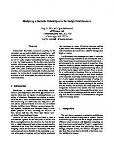
Figure 1. PC Module of SMART Robot
modules than provide processing and control, movement and necessary specialised functionality. 3.1. Modules Modules are base components of the system and are classified into three types: power-control module, joint module and specialized module. The modules take into consideration the need for flexibility in using the basic components and partial upgrades of modules as need arises. The separation of modules is based on their functionality and benefits for the ionising radiation facilities. As the modular robot will have to perform some complex operations like reaching a hard to plan location or searching for the best reconfiguration for a new task during operation. The heterogeneous robot design also helps compensate the inability to expand of functions a robot can perform in comparison with homogeneous robots. Power-Control Module (P-C) in SMART is a 150 mm x 55 mm x 90 mm cuboid Figure 1. It has been designed to decouple the electronics, communications and power source from the rest of the modules. The advantages, control being in a separate module, the module can be better shielded and reduce the risk of failure due to SEUs and accumulated dose. It also allows the use of additional computational units with the module and easy upgrade in the future as the technology improves. It is currently connected with permanent connector achieved by manual screws but a connector mechanism is being designed to ensure easy docking and undocking using the least amount of energy. Joint module (J) represents any type of active or passive actuator such as linear, rotary, pneumatic hydraulic, spherical, etc. In this case, an actuator with 3 rotational degrees of freedom whose axes intersect at one point is used. This module [17] has been reused from the first prototype of SMART modular robot system after a study was conducted for its use with the constraints and requirements. Figure 2 shows the actuator module and the axis of rotation and their intersect at the same point. The design of the J module allows S or P-C modules to be attached and detached depending on the task performed, through the permanent connector at its
3. Modular Robot System To overcome the constraints and needs of a wide range of tasks the second iteration of SMART [10, 16] heterogeneous modular robot system is presented. It also takes into consideration the need for different capabilities, along with robustness and safety. It is a heterogeneous modular robot system composed of three different basic www.intechopen.com
(a) J Module
(b) J Module 2
Figure 2. Joint Module of SMART Robot
Prithvi Sekhar Pagala, José Baca, Manuel Ferre and Rafael Aracil: Modular Robot System for Maintenance Tasks in Large Scientific Facilities
3
Figure 4. W2M Robot Configuration
to respective J modules and P-C module), it functions as a two wheeled robot capable of differential drive and rotation around its pivot as seen in figure 6.
Figure 3. S Module of SMART Robot
Figure 5(a) shows the two legged locomotion robot configuration (L2M - Two leg S modules attached to respective J modules and P-C module), it functions as a two legged robot with limitd leg motion but can be easily upgraded to four or six legs for better legged locomotion. Figure 5(b) shows the Arm robot configuration (H2M -
ends. It is mandatory to have J module attached to a P-C module to ensure the working of the J module. Specialized module (S) may be described as the end-effector of the robot and connection attachments between modules. It may be a an attachment to help locomotion like wheel (W) and leg (L), a sensor device like radiation measurement, a tool (e.g. gripper), an accessory (e.g. additional energy platform).This type of module can be attached to a P-C module, J module or other S module. The S module provides flexibility and diversity to locomotion and manipulation tasks. Examples of S modules used as wheel S modules is shown in Fig.4 and as an probe or hand S module in Fig.5(b). The example of using two S module is show in forming the legged locomotion robot configuration in Fig.5(a). The use of reconfigurable modular design approach increases the reusability and cost effectiveness of various robot configurations due to reuse of the modules. The ability to reconfigure the functions of the J modules and S modules helps the robot in planning and adjusting to different beam heights, positions and tasks. An examples, remote inspection of a control console or radiation sampling at different locations and beam heights with varying restrictions like angle, position of reach. One of the ways fault tolerance can be achieved is through redundancy, similar to what is done in spacecraft to ensure high degree of safety by having multiple units performs same task and cross validating each other to detect faults. Also, when there is a total or partial failure in a joint module at runtime, then reconfiguration of the robot configuration can be done to recover the lost functionality. Having a modular approach also make it easier to replace modules due to maintenance and failure. 3.2. Robot Configurations Three robot configurations achieved by the SMART modular robot are explained (wheeled configuration, legged locomotion configuration and basic arm configuration) and in the next section the simulation models are generated along with verified functionality. Figure 4 shows the two wheeled locomotion robot configuration (W2M - Two wheeled S modules attached 4
Int. j. adv. robot. syst., 2013, Vol. 10, 394:2013
(a) L2M Configuration
(b) H2M Configuration
Figure 5. SMART Robot Configurations
Two hand S modules attached to respective J modules and P-C module), it functions as two basic arm configuration with 3 DoF (degrees of freedom) in each arm or as a single unit of 6 Dof to perform basic manipulation tasks. 4. Simulation Results and Discussions Modelling of a modular robot system is complex due to its capability of changing and forming different robot configurations with a set of modules. The greater the number of modules added to the structure, the more complex its model. Therefore, simulation is used to exploit and access the different robot configurations of modular robot. The simulation model for SMART is obtained through the characterization of the geometric and kinematic model of each module of the modular robot system. The resulting simulated configurations exhibit the same kinematic parameters as the prototype model of the SMART robot. SMART has three types of the fundamental modules P&C Modules, J Modules and S Modules the methodology to represent modular robot configurations is achieved as a fixed shape robot for the prototype. The fixed shape robot configurations help to simplify the complexity of the robot model. To achieve simulation environment and models a three dimensional simulator Gazebo [18] is used to simulate the robot configurations and the different models. Gazebo is a physics based 3D environment for robots and is capable of simulating a population of robot models, sensors and objects. It generates realistic sensor feedback and rigid-body physics. Model of W2M robot configuration (Figure 6) featuring different functionalities that can be achieved by this www.intechopen.com
(a) Wheel rotation
(b) Joint rotation
(c) Tangential
Figure 6. W2M simulation model of SMART system
robot configuration are shown. Figure 6(a) shows the wheel rotation. It can perform bi-directional rotation or differential drive rotation to rotate around the center of the robot. Figure 6(b) shows that the along the vertical axis to enable the robot to be able to stand on its wheel. Figure 6(c) shows the joint rotation for tangential movement. The different robot configurations mentioned can be used as subcomponents to create robot configurations for a specific task. Figure 7 shows the SMART robot configuration using six wheeled robot configurations (W1M is a single wheeled robot configuration with two J modules, corresponding P&C module and only one wheel S module) as subcomponents of the robot configuration to perform manipulation and locomotion tasks. Similarly another alternative configuration using 3 W1M’s in the robot configuration is shown in figure 8. In both cases (using six W1M and three W1M robot configurations) they are connected with additional modules like the base S module, tool case S module and powerbase S module depending on the need and will be called as MRC6 and MRC3 respectively(Modular Robot Configuration with 6 W1M and 3 W1M). Colour code: Grey- J module, Blue- P&C module, BlackWheel S module, Dark Red- Connector Interface , Dark grey- Base plate S module, Grey pole and Black or Red cylinder - Camera or radiation probe S-module respectively. The MRC6 robot configurations in reduced footprint size (165 mm x 160 mm) complies with the width and height size restriction imposed by the access door requirement as seen in fig 7(d) and the baseplate can be extended in length to add more modules depending on the needs of locomotion and task. To reach target location MRC6 is able to exhibit both wheeled and legged locomotion as seem in Figures 7(a) and 7(b). Wheeled locomotion is advantageous on flat surfaces, while the
(a) Wheeled locomotion (b) Legged locomotion
(c) Reduced footprint - Top View
(d) Orthogonal View
(a) Locomotion
(b) Radiationinspection
Figure 8. SMART MRC3 Robot configuration with power base
legged locomotion for negotiating steps. The robot configuration is also able to reduce its footprint fig 7(c) and traverse through different sections using the special access doors. This shows the robot configurations capability to negotiate complex structural challenges, reach various positions along the tunnel and varying beam heights to reach the target location and perform the necessary tasks. The requirement of custom tools necessary to perform specific task has been addressed with the use of tool case S module on top and bottom of the base plate S module which hold the necessary tools for each section and the task. The tools are either individual S modules or a combination of many S modules e.g. camera, lighting, gripper or gripper with camera and lighting being used as a single tool. The requirement of long endurance for situations where manipulation and inspection needs to be performed for long hours is made possible with the help of power base S module that provides 4 hours of working time and also functions as a support for the robot configuration. The power base is equipped with spring loaded ball transfer unit on the floor surface to provide least friction during locomotion and a support structure during manipulation or inspection tasks as seen in figure 8. The power base S module are stored along with other section specific tool modules in safe zones away from the radiation behind concrete shield in each section near the access gates. Hence the robot can leave behind the used power base in the charging station after use and travel to the next section in its reduced footprint profile, attach with a new power base and pick the necessary section tools to continue work. Figure 8(a) shows the 3 legged SMART performing wheeled locomotion and the figure 8(b) shows the robot performing radiation survey (Radiation probe S module in light red). Two experimental robot configurations to perform manipulation on the maintenance consoles are the MRC6 configuration Figure 9(b) and MRC3 configuration Figure 9(a) with the power base which can be chosen depending on the requirement of the task and length of task execution. The arms need to pick the S modules attachments needed for the task from the tool case on the top and bottom of the baseplate. In Figure 9 two arms have picked the gripper tool which is made of camera, light and gripper S modules and the third arm holds a stereoscopic camera to provide a overview of the operation with depth perspective. This configuration helps the operator in the control station by providing an additional arm that can be moved to the best overview location to perform the task with the other two arms.
Figure 7. SMART MRC6 Robot configuration
www.intechopen.com
Prithvi Sekhar Pagala, José Baca, Manuel Ferre and Rafael Aracil: Modular Robot System for Maintenance Tasks in Large Scientific Facilities
5
manipulation task location to perform the task needed, by attaching necessary tools as shown in Figure 10(a). After completing the task, it returns the tools and detaches from powerbase. The robot reduces its footprint and moves between beamlines on a raised platform to perform radiation survey using the radiation probe Figure 10(b). After completion reaches the third section to perform remote inspection Figure 10(c) using camera S module. Lastly, returns and the location of the powerbase S module and continues to the next task. 5.1.1. Remote Manipulation for Maintenance (a) with powerbase
(b) without powerbase
Figure 9. SMART Robot remote manipulation
The SMART robot prototype and simulations confirm the feasibility of modular robot system to reach the target location in the tunnel through modified access doors and perform remote inspection, environment survey, manipulation. Although the platform presents many advantages, care needs to be taken in providing the operator with an intuitive human machine interface. As, the number of degrees of freedom (DoF) are large e.g the MRC6 configuration has 12 joint modules. hence, depending on the type of joint module used the DoF vary between 12 DoF (using 1 DoF J modules) and 36 DoF (using 3 DoF J modules). The redundant DoF during a task execution needs to be managed to improve the efficiency and flexibility of robot configuration. The execution of the tasks in mock-ups and simulation provides an opportunity to optimise the task execution prior to deployment in real environment. It also provides the operator with possible alternative robot configurations with respect to different needs (energy optimisation, completion speed and others), which is beneficial for task execution. 5. Applications and Advantages 5.1. Applications The applications of the heterogeneous modular robot system SMART prototype along with the simulator are in remote manipulation, inspection, training and emergency response. Figure 10 shows one of the applications of the Modular robot system using simplified workspace and the various tasks that are expected to be performed by the Modular robot in the Super Proton Synchrotron (SPS) secondary beam fan out from the targets in SPS North area [15]. In this workspace multiple beamlines of varying outer dimensions are present along with structural and size restrictions (raised platforms, narrows space between the beamline supports, etc.). The tasks needed to be performed are split as follows. Remote manipulation at first location, radiation survey at the second and remote inspection at the third location. MRC3 configuration is used to perform the task. The robot enters the section through the access door in the reduced footprint orientation like in Figure 7(d). It reaches the stored powerbase S module in the section behind shielding attaches itself along with picking up the necessary S modules (standard S modules and hybrid S modules like camera and grippers with light, camera etc.) for the task execution in the section. Next, reaches the 6
Int. j. adv. robot. syst., 2013, Vol. 10, 394:2013
The modular robot systems primary goal is to perform various maintenance tasks, which are performed by remote manipulation from the control room and range from manipulation on the equipment console to checking alignments of equipment and corrective maintenance of failures. The system adapts to the different accelerators facilities and their specific maintenance requirements by adjusting to the different beam height and using accelerator specific specialised (S) modules. 5.1.2. Remote Inspection and Radiation Survey Various accelerator work with different particles and energy levels therefore the beam lines and tunnel varies. During inspection and survey the modular robot is able to adapt and various illumination level, height and structural limitation to perform inspection of the facility. The Radiation protection (RP) group usage of the robot to get quick radiation maps of the facilities immediately after shutdown and not requiring to wait during the cool down time would reduce downtime of the facility. Repeated surveys and inspection during the cooldown time would facilitate the different groups to understand and plan the required maintenance depending on the detailed state of the facility provided by the robot deployment. It also prevents the exposure of the RP group with the residual ionising radiation during RP surveys. 5.1.3. Emergency Response In case of emergency the emergency personal or the fire brigade can use the system to access and assess the situation, and if possible avert the emergency. The robot system would act as the first person on the site in giving an assessment of the emergency. Special modules can be designed specific to the challenges of emergency response. As, the modular robot is designed for an unstructured environment with narrow access gates, it is in a better position than a conventional robot to act as an emergency response robot. 5.1.4. Others The modules of the SMART system can also be used to perform specific task with users or existing infrastructure. Two examples are: First, the use of S-modules with only P-C module, where the actuation is provided by user or other equipment (cranes, magnet vehicles etc.) like the use of the camera and light modules by an operator to view and record data. Secondly, the use of the modules to create www.intechopen.com
(a) Remote manipulation
(b) Radiation survey
(c) Remote Inspection
Figure 10. Simulation model of SMART system performing various tasks
a modular arm which could be added as auxiliary module to the TIM (Train inspection monorail) [13] in LHC (Large Hadron Collider) tunnel. 5.1.5. Training and Testing The simulator is useful to accelerate the ability to test new possibilities and configurations of the robot. It is also expected to train operators for the deployment and during the operation of the modular robot. The simulator provides the opportunity to add the CAD (Computer-aided design) models of the facility along with models generated from the stereoscopic cameras and lasers. It therefore reducing the time taken to recreate models of the remote environment and provides a realistic environment for testing and training. Designs of various additional modules and robot configuration can be tested which could lead to improvements for the robot configuration and future prototypes. 5.2. Advantages Along with advantages of a modular robot system over conventional robot like adaptability, lower cost, etc. the SMART modular robot design provides easier upgrade of each module. Especially, the power and control (P-C) module. Also, additional higher computational P-C modules can be added to provide higher level control and execution of algorithms for autonomy. 5.2.1. Optimisation and planning The robot configurations execution of tasks in the mockup of the workspace and the simulator would increase the optimisation and planning of the modular robot movement [19] and not only in task execution by reducing redundant movement but also in reducing the overall radiation dose taken by different modules. In the simulator, tests with various approaches can be experimented with the logged data from the deployment or from simulated data. 5.2.2. Fault tolerance and Detection Fault tolerance can be achieved by using redundant modules, similar to what is done in space crafts [20] to ensure high degree of safety by having multiple units performing the same task and cross validating each other to detect faults. Also, when a joint module fails the other modules can compensate for the lost degree of freedom by reconfiguring their functions. In case of total failures of an entire module, the other modules facilitate in the recovery and return to home location. Repair of the robot www.intechopen.com
is easier due to the use of few modules which facilitate easy replacement. Fault detection can also be achieved by comparing the prior logged data with the same task being performed in the remote location. Extension of this process would be to create respective models for the various tasks, which facilitates in detecting and predicting faults. 6. Conclusion and Future Work The modular robot system offers advantages over conventional robots in terms adaptability, cost effectiveness and fault tolerance. This works shows the possibility of deployment of a modular robot platform in an ionizing radiation facility to perform basic maintenance and reduce the downtime of the facility. SMART prototype has been designed to meet the requirements gathered from the scientific facility CERN for its maintenance tasks. The design has been choose after evaluating various configurations, requirements and simulations. The prototype is to be used as an evaluation platform for testing the system for safety and robustness of the modular system. After evaluation the deployed robot would be scaled in size and the materials used would be radiation hardened. In the future, there could be fault tolerant, robust and safe modular robots that can avoid human intervention in hazardous environments. Better strategies to manage the redundant degrees of freedom, safety and fault tolerance properties would be investigated along with human machine interfaces to control the modular robot system, as with addition of modules leads to more complexity. 7. Acknowledgment This research project has been supported by a Marie Curie Early Stage Initial Training Network Fellowship of the European Community’s Seventh Framework Program under contract number PITN-GA-2010-264336PURESAFE and TeleScale project DPI2012-32509 funded by ’Ministerio de Economía y Competitividad’ of Spain. 8. References [1] E Kugler, D Fiander, B Johnson, H Haas, A Przewloka, H L Ravn, D J Simon, and K Zimmer. The new CERN-ISOLDE on-line mass-separator facility at the PS-Booster. Nuclear Instruments and Methods in Physics Research Section B: Beam Interactions with Materials and Atoms, 70(1):41–49, 1992. [2] Hunt K Horne R A , Lohmann K D , Coull L , Coin A Y , Therville A , Lips R , Desrozier M. Prithvi Sekhar Pagala, José Baca, Manuel Ferre and Rafael Aracil: Modular Robot System for Maintenance Tasks in Large Scientific Facilities
7
[3] [4]
[5]
[6]
[7]
[8]
[9]
[10]
8
MANTIS: a compact mobile remote handling system for accelerator halls and tunnels. ANS Meeting on Remote Systems and Robotics in Hostile Environments, 30(CONF-7811109-), 1978. R Cohen, M G Lipton, M Q Dai, and B Benhabib. Conceptual Design of a Modular Robot. ASME Journal of Mechanical Design, 114(1):117–125, 1992. A Kusiak and Chun-Che Huang. Development of modular products. IEEE Transactions on Components, Packaging, and Manufacturing Technology, Part A, 19(4):523–538, 1996. Toshio Fukuda, Martin Buss, Hidemi Hosokai, and Yoshio Kawauchi. Cell Structured Robotic System CEBOT - Control, Planning and Communication Methods. In Intelligent Autonomous Systems 2, An International Conference, pages 661–671, Amsterdam, The Netherlands, The Netherlands, 1989. IOS Press. Mark Yim, Wei-Min Shen, Behnam Salemi, Daniela Rus, Mark Moll, Hod Lipson, Erick Klavins, and Gregory S Chirikjian. Modular Self-Reconfigurable Robot Systems [Grand Challenges of Robotics]. IEEE Robotics & Automation Magazine, 14(1):43–52, March 2007. Takafumi Matsumaru. Design and control of the modular robot system: TOMMS. In Robotics and Automation, 1995. Proceedings., 1995 IEEE International Conference on, volume 2, pages 2125–2131. IEEE, 1995. H Kurokawa, E Yoshida, K Tomita, a Kamimura, S Murata, and S Kokaji. Self-reconfigurable M-TRAN structures and walker generation. Robotics and Autonomous Systems, 54(2):142–149, February 2005. M W Jorgensen, E H Ostergaard, and H.H. H Lund. Modular ATRON: modules for a self-reconfigurable robot. In Proc. IEEE/RSJ Int. Conf. Intelligent Robots and Systems, volume 2, pages 2068–2073. Ieee, 2004. J Baca, M Ferre, R Aracil, and A Campos. A Modular Robot System Design and Control Motion Modes for Locomotion and Manipulation Tasks. In Proc. IEEE/RSJ Int. Conf. on Intelligent Robots and Systems, 2010.
Int. j. adv. robot. syst., 2013, Vol. 10, 394:2013
[11] A Aviziens. Fault-tolerant systems. Computers, IEEE Transactions on, 100(12):1304–1312, 1976. [12] Antonella VIGNES-MAGNO. Radiation Protection Safety Code. Geneva, 2006. [13] K. Kershaw, F. Chapron, a. Coin, F. Delsaux, T. Feniet, J-L. Grenard, and R. Valbuena. Remote inspection, measurement and handling for LHC. 2007 IEEE Particle Accelerator Conference (PAC), pages 332–334, 2007. [14] P E Dodd and L W Massengill. Basic mechanisms and modeling of single-event upset in digital microelectronics. Nuclear Science, IEEE Transactions on, 50(3):583–602, June 2003. [15] CERN. SPS secondary beams fan out from targets in the hall TCC2 towards North Area experimental halls. March 1978. [16] José Baca, Manuel Ferre, and Rafael Aracil. A heterogeneous modular robotic design for fast response to a diversity of tasks. Robotics and Autonomous Systems, 60(4):522–531, April 2012. [17] Ariadna Yerpes, J Baca, J A Escalera, M Ferre, R Aracil, and JA Baca Garcia. Modelling of Modular Robot Configurations Using Graph Theory. In Proc. Int. Conf. on Hybrid Artificial Intelligence Systems, volume 1, pages 889–894, 2008. [18] N. Koenig and A. Howard. Design and use paradigms for gazebo, an open-source multi-robot simulator. In 2004 IEEE/RSJ International Conference on Intelligent Robots and Systems (IROS) (IEEE Cat. No.04CH37566), volume 3, pages 2149–2154. IEEE. [19] Amit Pamecha, G.S. Gregory Chirikjian, and I. Ebert-Uphoff. A useful metrics for modular robot motion planning. IEEE Transactions on Robotics and Automation, 14(4):531–545, 1997. [20] D Zhuo-hua, C Zi-xing, and Y Jin-xia. Fault diagnosis and fault tolerant control for wheeled mobile robots under unknown environments: A survey. In IEEE International Conference on Robotics and Automation, number April, pages 3428–3433, 2005.