13th IEEE International Conference on
Emerging Technologies and Factory Automation 15 – 18 September 2008, Hamburg, Germany
Modular Wireless Fieldbus Gateway for Fast and Reliable Sensor/Actuator Communication Ralf Heynicke Helmut-Schmidt-University Hamburg, Germany
[email protected]
Dirk Krüger Helmut-Schmidt-University Hamburg, Germany
[email protected]
Housam Wattar Helmut-Schmidt-University Hamburg, Germany
[email protected]
Gerd Scholl Helmut-Schmidt-University Hamburg, Germany
[email protected]
Abstract
power consumption of 10 mW could be realized. With respect to system response and cycle times our goal was to achieve AS-i comparable performance in a production cell with typical dimensions of 5 x 5 x 3 m3. In the following section II system design will be described, especially the architecture of the wireless gateway and section III is dedicated to coexistence considerations with special focus on WLAN coexistence.
The AS-Interface (AS-i) is a simple and costeffective network solution connecting simple I/O devices to the upper fieldbus levels. A fully loaded AS-i Version I network with one master and 31 slaves has a maximum response time of 5 ms per I/O. The AS-Interface has been chosen as reference system for the development of a wireless fieldbus gateway, which will be presented in this paper. Standard modules have been employed to achieve a price-competitive solution. A high reliability level with wireless system can only be achieved if radio wave propagation characteristics and coexistence to other radio services are taken into account. Especially wireless local area network (WLAN) technologies already installed in the field can affect proper sensor/actuator network operation. Therefore bit and frame error probabilities in the presence of WLAN systems also have been investigated.
1. Introduction A market research in the German public funded project EnAS [1] and customer interviews carried out by FESTO, the lead manager of the consortium, delivered the following requirements for a wireless sensor/actuator network for factory automation: high reliability, i.e. packet error rate comparable to wired fieldbus systems, real-time capability and multisensor/multiactuator handling, scalability and modularity, coexistence with other standards and energy autonomous operation, as the user only has full benefit of wireless systems if not only communication lines but also power lines are cut. If an extremely high reliability with bit error rates as low as 10-9 and very short response times are required options for energy-savings are very limited, but using the built-in power saving modes of modern low-power radio transceivers a mean
2. Modular Fieldbus Gateway for RealTime Sensor/Actuator Communication Highly matured network solutions for process and building automation are already available [2]. Commonly radio platforms based on IEEE 802.15.1/Bluetooth, IEEE 802.15.4/Zigbee or proprietary solutions developed for ISM-band applications are employed. Therefore these radio platforms are also a good candidate for physical layer implementation for device level communication. But due to different requirements, mainly latency and real-time behavior, complete network solutions cannot be transferred to factory automation applications. Up to now only the WISA system [3] is commercially available for fast and robust wireless sensor/actuator communication and the feasibility of this approach has been proven with many installations in the field. With our prototype system, however, we wanted to investigate if a similar performance could also be achieved by employing standard components, especially for the gateway connecting the wired with the wireless world. To ensure a high design flexibility, we have chosen an approach based on a Xilinx Spartan 3 field programmable gate array (FPGA), offering a high degree of freedom for implementing module functionalities either in soft- or hardware. The architecture of our
13th IEEE International Conference on
Emerging Technologies and Factory Automation 15 – 18 September 2008, Hamburg, Germany prototype system, realized on standard FR4 epoxy, is shown in Figure 1.
respect to the number of pieces and component costs the price of low-power RF transceiver modules is significantly lower than e.g. the price of antennas, connectors, electromagnetic shielding mechanisms or an industrial-grade housing.
Figure 1. Wireless gateway architecture. The JTAG interface in conjunction with several LEDs and DIP-switches allow efficient system debugging. Conform to standards like PROFINET or Ethernet/IP communication with an upper level control unit, e.g. a programmable logic controller or a personal computer, is carried out over a LAN interface employing the UDP/IP or TCP/IP protocol stack. To achieve multifrequency operation, the wireless interface is realized with four low-power radio frequency (RF) transceiver units, denoted by Rx/Tx #1 - Rx/Tx #4 in Figure 1. The same RF transceiver units are also used for the distributed sensor/actuator modules (SAMs). This implementation is mainly software based as the complete communication, i.e. communication with the upper level control unit as well as communication with distributed wireless SAMs is controlled by a software program running on the embedded MicroBlaze processor, a 32-bit RISC CPU. LMB is the local memory bus between CPU and BRAM, the program and data memory. OPB is the on-chip peripheral bus. For low-latency RF communication three modules were implemented, denoted by RF-Time, RF-Ctrl and SPI-Ctrl. RF-Time is a timing module delivering precise trigger signals for Rx/Tx-switching, RF-Ctrl checks RF transceiver status informations and generates together with the timing module Rx/Tx control signals. SPI-Ctrl is used for RF transceiver configuration and data transfer. A photo of the prototype system with four RF transceiver modules and a WLAN module is shown in Figure 2. The modular design of the wireless gateway offers a high flexibility for tailoring the system to specific applications. In principle this system allows multi-band multi-standard operation, i.e. different RF standards and radio hardware platforms can be employed, operating in different frequency bands at the same time. Surely, the current trend in radio design to cope with different standards are RF reconfigurable systems, but with
Figure 2. Wireless gateway with four RF transceiver modules and a LAN interface module. Also development costs are significantly lower if established radio technologies or communication standards are substituted by newer ones. In our approach RF chips, which are not supported anymore, only have to be substituted by state-of-the art devices without the need for adapting higher network protocol layers, e.g. medium access or logical link control layers or customer specific application profiles. Additionally, various diversity schemes like frequency-, time- or antenna diversity can be implemented easily, which are vital to achieve a high robustness against fading, shadowing and interference mechanisms. We organized the sensor/actuator network in a star topology and implemented a classical F/TDMA scheme, where 32 sensor/actuator nodes were allocated in four frequency tracks and eight time slots per track. For wireless network coexistence the SAM RF carrier frequencies were chosen between WLAN bands 1, 7 and 13, respectively, and a frequency hopping algorithm was implemented, i.e. after each communication cycle SAMs hop to a new carrier frequency. Figure 3 shows the power spectral densities (PSD) of sensor/actuator communication signals embedded between three WLAN bands, operating in the IEEE 802.11g mode. Our investigations were made with Chipcon/TI CC2400, CC2420 and Nordic nRF24L01 RF modules, but due to the limited space in this paper we here only present the results for the CC2400 devices. For test measurements, protocol design and system development the prototype system shown in Figure 1 was developed for highest flexibility and thus most of
13th IEEE International Conference on
Emerging Technologies and Factory Automation 15 – 18 September 2008, Hamburg, Germany the system functionalities were implemented in software. An alternative approach is depicted in Figure 4, a hardware-based high-speed implementation of the wireless gateway. Each RF transceiver is controlled by a finite state machine, denoted by FSM #1 - FSM #4, that can be subdivided into two submodules, RF-Ctrl and SPI-Ctrl, respectively.
Figure 3. Sensor/actuator communication in coexistence with three WLAN bands visualized in the frequency domain. SPI-Ctrl serves for time-parallel configuration and data transfer to and from the RF transceiver units. SPI-Ctrl also automatically reads data from the Dual-Port RAM, if new information is available. RF-Ctrl checks RF transceiver status informations and generates all instructions for RF transceiver control, i.e. adjust to new frequency, transmit, receive or initialize.
allows to speed-up performance significantly. An example is given in Figure 5, where the spectrogram of sensor/actuator communication embedded between three 802.11g-WLAN bands is shown. Measurements in Figure 3 and Figure 5 were taken with a Tektronix RSA 6100A real-time spectrum analyzer.
Figure 5. Spectrogam of sensor/actuatorcommunication between three WLAN (IEEE 802.11g-standard) bands. A complete communication cycle, i.e. communication down from the gateway to the SAMs and back from the SAM to the wireless gateway can be realized in 1.5 ms. In both, the downlink and uplink frames, one byte of information is carried for each SAM. Our measurements and simulation results have shown that packet error probability due to fading, shadowing and interference should be less than 10-3. Therefore we expect that with 3 retries within 5 ms in the down- and uplink a bit error probability as low as 10-9 can be achieved. Of course, in the majority of cases intelligent diversity schemes have to be employed. Nevertheless, a wireless sensor/actuator network with a performance comparable to a wired AS-i bus can be realized. At the moment we are preparing several field test to prove our expectations.
3. Wireless Network Coexistence
Figure 4. High-speed wireless gateway. Substituting a RF radio module by a radio module operating with another RF modulation format or standard only requires to modify the RF-Ctrl finite state machine. Dual-Port RAM Ctrl coordinates RAM access by FSM1#1 - FSM#4 and their submodules. Different medium access algorithms and logical link control are realized in a software module running on the MikroBlaze. The architecture shown in Figure 4
In contrast to public spaces frequency management can be made in industrial environments. A scenario often seen in factory automation is that already shown in Figure 3 and Figure 5, i.e. communication over three parallel operating WLAN bands that are already installed in the field and an additional wireless sensor/actuator-network that has to cope with this situation. Some of the results of our coexistence analysis are condensed in Figure 6, where bit error probability (BER) of a CC2400 communication link affected by a 802.11b-WLAN link is shown. Parameter is signal-to-interference ratio (SIR), where a negative SNR means that the desired signal at the CC2400 receiver is smaller than the signal received from the WLAN interferer operating at a frequency distance of f MHz.
13th IEEE International Conference on
Emerging Technologies and Factory Automation 15 – 18 September 2008, Hamburg, Germany
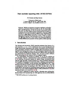
Figure 7. Measurement setup for evaluation of frame error probability.
Figure 6. Bit error probability depending on frequency-offset f and SIR. The shape of the probability error curves show a high correlation with a WLAN PSD operating in the 802.11b mode. Minimum bit error probabilities can be achieved at an offset of about 11 MHz. To avoid corruption of measurement results by other interferers measurements were carried out with a wired measurement setup. The WLAN interference signal is generated by a Rohde&Schwarz SMU200A signal vector generator (VSG), transmitting a continuous pseudo random bit sequence with a data rate and modulation format conform to the 802.11b standard. The VSGsignal is coupled into the communication path between two CC2400 transceiver units by a 3dB-power combiner. Output power level (0 dBm) and operating frequency of the CC2400 radios were fixed, but the CC2400 output power level was reduced by a 60 dB attenuator to have a scenario comparable with realworld applications. Frequency offset f and SIR, i.e. WLAN power level, are adjusted by the VSG.
As can be seen from Table 1, WLAN interferers affect frame error probability not significantly, as can be seen when frame errors in the “on-state” are compared with frame errors in the “off-state”. Maximum frame error probability in this measurement setup is approximately in the order of 10-3.
WLAN “off” WLAN “on”
SAM1 < 106 < 106
Frame Error Probability SAM2 SAM3 SAM4 1.310-5 3.510-4 510-4 210-5 1.110-3 4.710-4
Table 1. Frame error probability for the configuration shown in Figure 7.
4. Conclusion In this paper the feasibility of a wireless sensor/actuator network with a performance comparable to a wired AS-i bus has been demonstrated on the basis of standard RF technologies and a FPGA-based system approach. The prototype systems will be tested in the field during the next months. Another focus of our future work will be system simulation and reliability. Acknowledgement
To study error probability in more detail we also made measurements in our laboratory, where the wireless gateway was located in direct line-of-sight in close proximity to three WLAN links. The configuration is given in Figure 7. Each WLAN clients was connected with a Laptop-Computer and a bi-directional file-transfer between Laptops was accomplished. Distances d1 = d3 were chosen to 1 m, distances between WLAN routers and the wireless gateway to d2 = 3 m. SAMs operated at 2424 MHz, 2430 MHz, 2454 MHz and 2460 MHz, respectively. Output power was 0 dBm and omnidirectional dipole antennas have been used. WLAN equivalent isotropic output power was set to 20 dBm. Measurements were carried out with WLAN-clients and -routers in the off- and onstate. Frame error probabilities are given in Table 1. Under frame error we understand an error occurring in a communication cycle, either in a downlink message or an uplink-message.
Part of this work has been supported by the Federal Ministry of Economics and Technology under the roof of the Next Generation Media Programme in the EnAS project. We would like to thank our project partners, especially Bernd Kärcher at FESTO, the lead manager of the consortium, for continuous support and encouragement. References [1]
[2]
[3]
Governmental Funded Project: “EnAS – Energy Autarkic Wireless Actuator and Sensor Networks,” http://www.nextgenerationmedia.de. Wireless HART, “Wireless Communication Standard for Process Industry,” http://www.hartcomm2.org/ hart_protocol/wireless_hart/wireless_hart_main.html ABB Stotz-Kontakt GmbH, Germany, “White Paper: Introduction to Wireless Interface for Sensors and Actuators and Wireless Proximity Switches,” Aug. 2004.