Apr 13, 2013 ... would provide an alternative, robust approach to process multinary compounds ...
Since the introduction of molecular solution approaches, high.
Article pubs.acs.org/JACS
Molecular Solution Approach To Synthesize Electronic Quality Cu2ZnSnS4 Thin Films Wenbing Yang, Hsin-Sheng Duan, Kitty C. Cha, Chia-Jung Hsu, Wan-Ching Hsu, Huanping Zhou, Brion Bob, and Yang Yang* Department of Materials Science and Engineering, University of California, Los Angeles, California 90095, United States S Supporting Information *
ABSTRACT: Successful implementation of molecular solution processing from a homogeneous and stable precursor would provide an alternative, robust approach to process multinary compounds compared with physical vapor deposition. Targeting deposition of chemically clear, high quality crystalline films requires specific molecular structure design and solvent selection. Hydrazine (N2H4) serves as a unique and powerful medium, particularly to incorporate selected metallic elements and chalcogens into a stable solution as metal chalcogenide complexes (MCC). However, not all the elements and compounds can be easily dissolved. In this manuscript, we demonstrate a paradigm to incorporate previously insoluble transitional-metal elements into molecular solution as metal−atom hydrazine/hydrazine derivative complexes (MHHD), as exemplified by dissolving of the zinc constituent as Zn(NH2NHCOO)2(N2H4)2. Investigation into the evolution of molecular structure reveals the hidden roadmap to significantly enrich the variety of building blocks for soluble molecule design. The new category of molecular structures not only set up a prototype to incorporate other elements of interest but also points the direction for other compatible solvent selection. As demonstrated from the molecular precursor combining Sn-/Cu-MCC and Zn-MHHD, an ultrathin film of copper zinc tin sulfide (CZTS) was deposited. Characterization of a transistor based on the CZTS channel layer shows electronic properties comparable to CuInSe2, confirming the robustness of this molecular solution processing and the prospect of earth abundant CZTS for next generation photovoltaic materials. This paradigm potentially outlines a universal pathway, from individual molecular design using selected chelated ligands and combination of building blocks in a simple and stable solution to fundamentally change the way multinary compounds are processed.
■
to the ease of control film composition and volatile phases. The use of metal salts (e.g., chlorides and nitrates) could be considered one of the easiest and the most intuitive ways to introduce the various constituent elements into a CZTS precursor solution, since these salts offer good solubility in water and alcohol.12,13 The fabrication of monodisperse CZTS nanocrystals (NCs) can lead to binary or ternary subcomponent nanoparticles and enables a variety of synthetic approaches to control composition and phase formation by avoiding effects of the volatile precursor at high temperature.6,7 Unfortunately, those approaches cannot avoid some unnecessary impurities in the form of long carbon-chain ligands that stabilize the NC-based ink prerequisite to deposit uniform films in large areas. A new type of metal chalcogenide complex (MCC) usually prepared from hydrazine with excess chalcogen opens the door for a chemically clean NC system without introducing unnecessary impurities.14−16 Solutions based on all MCC constituents do not have the suspension stability issue. Since the introduction of molecular solution approaches, high quality semiconducting films have been achieved: CIGS films
INTRODUCTION The earth abundant chalcogenides of copper, zinc, and tin make up an important class of materials toward creating low cost and sustainable thin film solar cells, with the properties of a direct band gap with a large absorption coefficient.1,2 A variety of deposition techniques that were rapidly developed in recent years, both vacuum-based and nonvacuum solution processes, had success in boosting the power conversion efficiency from 6% to 11.1%.3−11 Though they are analogous to copper indium gallium selenide (CIGS), several challenges still limit the full extension of photovoltaic properties for these materials to the levels of CIGS devices. They include the nonidentified complex multinary phase diagram currently compromised with empirically established experience and some identified materials issues, a narrow phase stability field, difficulty to control stoichiometry, and phase purity.2 In order to fully extend the potential for kesterite copper zinc tin sulfide (CZTS) materials, of particular interest is to develop an effective processing platform to overcome the challenges associated with a multinary compound that contains volatile species. Solution processing of kesterite materials draws great interest, not only because of the potential low cost, highthroughput production but also decent device performance due © 2013 American Chemical Society
Received: December 28, 2012 Published: April 13, 2013 6915
dx.doi.org/10.1021/ja312678c | J. Am. Chem. Soc. 2013, 135, 6915−6920
Journal of the American Chemical Society
Article
deposited from the molecular level MCC precursor yields the highest efficiency for a pure solution deposition technique.17,18 Unable to design a Zn-based MCC ligand, the hydrazine-based slurry by making the compromise to use particles of hydrazinium zinc chalcogenide and soluble MCC of Cu and Sn constituents currently holds the most successful approach to fabricate kesterite CZTS photovoltaic devices.4,5 However, the formation of the slurry tends to be finicky, and the stability of the MCC ligands and particle systems has not been addressed. A fully dissolved molecular homogeneous solution capable of yielding chemically clean films is the most simple and effective way to process films of a multinary compound system, with each elemental component independently adjustable to control composition and phase. However the limited solubility of materials terminated this MCC concept only within the realm of a few materials but not Zn/ZnS/ZnSe and other transitionmetal-based chalcogenides of interest. Previously, we reported a solution processed CZTS with fully dissolving zinc constituent using hydrazine derivatives (HD).3 The introduction of the hydrazine derivative breaks the solubility limitation for previously insoluble materials. To fully understand the underlying mechanism in order to expand its application to other new material systems, we investigated the evolution of zinc−HD molecular structures in the dissolution process, solution stability, and the phase evolution reacted with Cu and Sn constituents toward kesterite CZTS. The identification of metal−atom hydrazine/hydrazine derivative complexes (MHHD) molecular structure serves as a lighthouse for molecular design to potentially incorporate a variety of other interested elements forming a stable molecular solution and compatible solvent exploration beyond hydrazine. Electronic properties based on CZTS transistors indicate the mobility is a similar level as the analogue CIGS, which points toward a promising future for CZTS materials and device technology to reach the level of CIGS. The enrichment of individual or combined molecular solution components provides a simple complementary route to process a multinary compound with the capability for robust composition control.
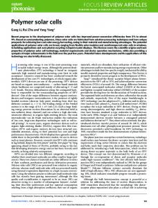
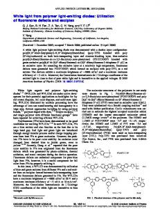
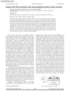
Figure 1. (A) Zn/Sn solution in hydrazine, by combining the zinc precursor reacted from metallic zinc and hydrazidocarboxylic acid, the SnS2 solution precursor in hydrazine, and extra sulfur. Atomic ratio between Zn and Sn is independently adjustable by controlling the zinc precursor and Sn solution. (B) Crystal structure of N2H5[Zn(NH2NHCOO)3]·H2O derived from the reaction of Zn and NH 2 NHCOOH in water. (C) Crystal structure of Zn(NH2NHCOO)2(N2H4)2, the soluble zinc complex from Zn/Sn solution in panel A. (D) Solution Raman spectroscopy of the Sn−S species in the SnS2 solution and Zn/Sn solution in panel A.
bidentate ligands with Zn−N and Zn−O bonds, the complex ion was electronically neutralized by the hydrazinium cation N2H5+, and the solvent molecule does not chemically bonded to the zinc atom but acts as a neutral spacer between ions. Rather than using extra chalcogen to dissolve soluble metal chalcogenide into hydrazine, in which excess sulfur inserted between the metal−chalcogenide covalent bond terminates the metal−chalcogenide framework, here, it is the chelates ligands that dismantle the metallic zinc lattice to form the individual unit of the Zn−hyc complex. But, the complex in Figure 1B still has a limited solubility in hydrazine existing as a white paste after continuous stirring. It was discovered that adding Sn constituent (1 mmol) with excess sulfur (0.5 mmol) into the zinc paste (1 mmol) greatly improves the solubility, forming the mixed Zn/Sn precursor with a Zn/Sn concentration around 1 M in this study.
■
RESULTS AND DISCUSSION By introducing carbon dioxide into hydrazine, the zinc constituent was incorporated in hydrazine in a fully dissolved form coexisting with a Sn−S solution. Figure 1A shows the Zn/ Sn precursor solution containing Zn and Sn constituents with the flexibility to adjust the metallic ratio. To achieve the soluble colorless solution, first, the elemental zinc constituent was combined with hydrazinocarboxylic (hyc) acid in hydrazine with bubbling observed when combining the reactants. Unlike the dimension reduction of the metal chalcogenide framework for the dissolution of soluble metal chalcogenides (SnS2, In2Se3, Cu2S) into hydrazine solution,19 the metallic zinc lattice was dismantled and coordinated with chelate NH2NHCOO through reaction 1:
[Zn(NH 2NHCOO)3 ]− + [Sn2S6]4 − + S + N2H4 → Zn[NH 2NHCOO]2 [N2H4]2 + [Sn2S7]6 −
To ascertain the molecular structure evolution, X-ray crystallography was applied to analyze the crystal of the Zn compound grown from the Zn/Sn solution by introducing H2O as a precipitant very carefully as shown in Figure 1C. The zinc atom is chelated by two NH2NHCOOH and NH2NH2 molecules. The incorporation of hydrazine into the zinc complex forms Zn(NH2NHCOO)2(N2H4)2 that exhibits greatly improved solubility compared with Zn(hyc)3.The Sncomplex evolution from Sn2S6 to a S-rich complex during the reaction was revealed by Raman spectroscopy on the molecular species in solution, as shown in Figure 1D. Before mixing with the Zn constituent, the Sn solution with the molecular structure of [Sn2S6]4− shows the bridging mode (Sn−S−Sn) and stretching mode at 344 and 367 cm−1, respectively, and the Sn2S2 ring vibration mode at 280 cm−1.20 While in the mixed Zn/Sn solution, the disappearance of the Sn2S2 ring vibration
Zn + NH 2NHCOOH → [Zn(NH 2NHCOO)3 ]− + H 2(g)
(2)
(1)
To investigate the resulting molecular structure, a crystal was grown from the Zn and NH2NHCOOH species in an H2Obased solution by slowly evaporating the solvent until the concentration saturated and precipitation began. Figure 1B shows the molecular structure of Zn(hyc)3 resolved from X-ray crystallography. The zinc atom was chelated by three hyc 6916
dx.doi.org/10.1021/ja312678c | J. Am. Chem. Soc. 2013, 135, 6915−6920
Journal of the American Chemical Society
Article
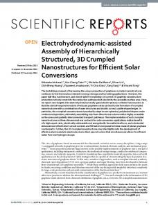
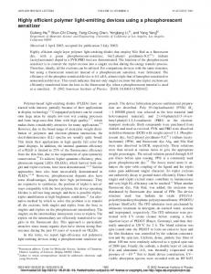
mode at 280 cm−1 and the appearance of peaks around 300 and 351 cm−1 suggest that excess sulfur terminates the symmetric Sn−S−Sn bridges in Sn2S6 to generate a new bridge vibration in S3Sn−S−SnS3 and a SnS4 stretching mode around 348 cm−1.21,22 Gradually increasing the amount of sulfur in the Zn/ Sn solution leads to a relatively stronger signal around 350 cm−1, showing a relatively larger portion of the SnS4 species in a Sn−S complex.22 Thus, the Zn/Sn solution in Figure 1A has the soluble form of Zn(hyc)2(N2H4)2 coexisting with multiple Sn−S species in equilibrium, including [Sn2S7] and [SnS4], determined by the amount of extra sulfur incorporated. The zinc constituent is effectively incorporated into N2H4 solution with greatly enhanced solubility coexisting with the Sn−S complex through chelation by two hydrazine molecules. This model, demonstrated in the case of zinc, to form both HD and N2H4 chelated complexes, is expected to provide a universal route to possibly incorporate previously nonsoluble elements into hydrazine and other solvents. As-prepared colorless Zn/Sn solution is stable for several months in an inert atmosphere. Even in the process of evaporating hydrazine solvent, no obvious precipitates showed up until the eventual transparent amorphous solid with a slight yellowish color. The zinc compound remained until the chemical environment was changed by introducing S ligands. It was observed that adding extra sulfur into the Zn/Sn solution (Figure 1A) with S−H ligands generates precipitates within several days. While in a stable Zn/Sn solution, no obvious S−H signal at 2560 cm−1 was observed via Raman spectroscopy. As shown in Figure 2A, the introduction of 1 mmol excess S into 1
Zn[NH 2NHCOO]2 [N2H4]2 + SH[N2H5] → ZnS + N2H4 + NH 2NHCOOH
(3)
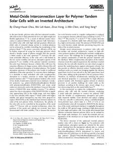
Composition analysis by X-ray photoelectron spectroscopy (XPS) (Figure 2B) showed that the S ligands destroy the stability of the zinc complex solution system, forming a ZnS precipitation within 1 day at room temperature. As it is thermodynamically stable, ZnS precipitated from the solution containing S ligands. This behavior is consistent with the mostly insoluble nature of ZnS using the approach of introducing excess sulfur into hydrazine.17 The effect of S ligands on the stability of the final CZTS precursor has also been verified when mixing with a serial of Cu−S−N2H4 solutions with decreasing S/Cu ratio. Figure 2C shows the freshly made Cu-constituent solutions: the color shift from yellow to brown is attributed to the absorption from increasing the excess sulfur dissolved in the hydrazine solution. The normalized S−H vibration signal from the solution-phase Raman spectrum at 2560 cm−1 (Figure 2D) reveals reduced S ligands with lower excess S. When mixing the Zn/Sn solution with a S-rich Cu constituent (S/Cu∼1.5), obvious precipitation of ZnS was observed after several hours. The composition analysis by XPS on the precipitates shows strong Zn and S signals and the absence of Sn and Cu signals (Figure 2B). The mixed solution of the Cu constituent with a smaller S ratio is stable for several days. The final mixture of a Zn/Sn solution with a Cu constituent of S/Cu∼0.75, with a barely visible S−H signal in Raman spectroscopy, was stable for several weeks without obvious aggregation. It is indicated that the Zn complex could also coexist with the Cu constituent in the form of Cu6S44−. The stability collapse in the mixed CZTS precursor behaves similarly to that of the Zn/Sn solution with extra sulfur. Therefore, by extrapolation of these findings, to achieve stable multinary molecular solutions, the incorporation of S ligands should be avoided when combining Zn or other metallic complexes with hydrazine/hydrazine derivative chelates of other constituents The molecular solution process provides a platform to further examine the mechanism of transformation from precursor solutions to a solid film with the desired phase. Compared with the solid-state reaction routes that covert binary phases into CZTS as demonstrated in the hydrazine slurry precursor and thermal evaporation,5,7,24 the molecular solution yields a final phase from an individual molecular in a single step. The final CZTS precursor solution has the flexibility to realize compositional control by varying the volume of each constituent solution. The evolution of the zinc complex with hydrazine incorporated as chelate ligands shrinks the thermal barrier to release Zn. Compared with the Zn(hyc)3 complex, which decomposed into metal/metal oxide powder above 500 °C with the major endothermic reaction around 200 °C, in contrast, the CZTS precursor containing the hydrazinecoordinated Zn complex shows exothermic behavior around 160 °C as shown in Figure 3C. The exothermic process is partially due to the incorporation of the hydrazine molecule on a zinc atom and hydrazinium species from Cu and Sn components.15 Another possible route is likely from the chemical modification of the Zn complex by sulfur ligands. While extra S ligands tend to disturb the stability of the solution system, control of the S ligands during film processing also provides a self-cleaning procedure to chemically strip hyc ligands from zinc. Differential scanning calorimetry analysis on
Figure 2. Stability of molecular species. (A) Raman spectroscopy from the Zn/Sn solution in Figure 1A. Incorporating extra sulfur leads to the formation of S ligands with a Raman signal at 2560 cm−1. (B) XPS result of precipitation formed adding excess S into the Zn/Sn solution. (C) Cu precursors with a serial of Cu/S ratio from 1:1.5 to 1:0.75. (D) Raman spectroscopy on Cu precursors showing the normalized intensity of S ligands in solution.
mL of Zn/Sn solution forms (N2H5)HS or ((N2H5)2S, which is evident by a strong Raman S−H signal.23 The appearance of S ligands in the system varies the complex coordination on the zinc atom: the formation of thermodynamically favorable Zn−S bond tends to strip the coordinated ligands of hyc and hydrazine molecules by replacing the Zn−N and Zn−O bonds. 6917
dx.doi.org/10.1021/ja312678c | J. Am. Chem. Soc. 2013, 135, 6915−6920
Journal of the American Chemical Society
Article
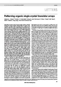
capability to acquire single-phase, chemically clean films, also provides a platform to examine the material properties correlating its structure and electrical performance. The crystalline semiconducting films were spin coated from CZTS molecular precursor solution, which allows the deposition of a continuous smooth film thinner than 10 nm. From atomic force microscopy (AFM) in Figure 4A, the
Figure 3. Reaction path from molecular precursor to kesterite CZTS phase. (A) X-ray diffraction (XRD) patterns and (B) Raman spectrum for CZTS precursors annealed with the maximum temperature at 100 and 250 °C. (C) Thermogravimetric analysis (TGA) on (I) Zn(hyc)3, showing an endothermic reaction around 200 °C, and (II) the CZTS precursor toward the kesterite phase with an exothermic decomposition around 150 °C. (D) Differential scanning calorimetry analysis on Zn(hyc)3 and the CZTS precursor.
Zn(hyc)3 and the CZTS precursor (Figure 3D) also shows the opposite thermal behavior, suggesting molecular structure evolution had occurred in the zinc complex system. Therefore, rather than solely thermal decomposition of the Zn complex, S ligands also provide an extra chemical route to extract zinc by replacing the coordinate ligands, which is accelerated by intermediate annealing. As a result, on a molecular scale, the homogeneously released zinc constituent reacts with Sn- and Cu-MCC molecular species, contributing to the kinetically favorable reaction path to form the CZTS phase at a low temperature around 200 °C without involving any long-range diffusion process.
(4)
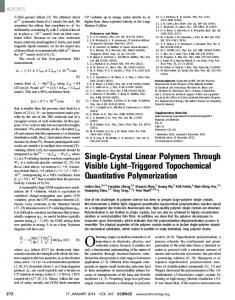
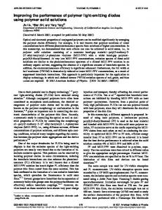
Figure 4. (A) AFM shows the roughness of less than 2 nm for CZTS films deposited on a Si/SiO2 substrate subjected to thermal treatment under 400 °C. (B) Composition analysis on CZTS film by RBS. The possible impurity of carbon is under the detection limitation of RBS. (C) Schematic of transistor structure using the CZTS film as the channel layer (channel length L = 200 μm, channel width W = 5000 μm) and gold as the source and drain electrode on SiO2/Si substrates using heavily doped Si as the gate terminal. (D) Typical source drain output of CZTS transistor plotted of Isd (drain current) as a function Vsd (drain voltage) when applying different Vg (gate voltage). (E) Hysteris effect of the CZTS channel-layer-based transistor. (F) Gatevoltage-dependent drain current at the saturation region.
The stripped molecule NH2NHCOOH itself evolved to gaseous species around 160 °C, much lower than the decomposition of the coordinated form. Further annealing up to 250 °C leads to the dissociation of a hydrazine/hydrazium/ hydrazine derivative into a volatile species (CO2 and hydrazine).25 Phase characterization of the product by XRD further verifies the evolution process regarding the dissociation of the spacer molecule. The strong diffraction peak at 8° in Figure 3A from the powder derived from evaporating solvent of the CZTS precursor, indicates a large d-spacing possibly separated by N2H5+/N2H4, which agrees well with other hydrazium compounds.26 The N−H stretching signal from the Raman spectrum (Figure 3B) also suggests the existence of a N2H5+/N2H4 spacer. The disappearance of the N−H signal upon the intermediate heat treatment of 250 °C is coherent with the simple thermal decomposition step from the hydrazium complex system to the metal chalcogenide product. For wider applications, the molecular solution process, with the
roughness of the film is within the range of 2 nm. The volatile nature of the hydrazinium cation and the hydrazine derivative enables the formation of a chemically clean highly crystalline CZTS phase below 250 °C. Upon 400 °C annealing, the chemical composition analysis (Figure 4B) on films by Rutherford back scattering (RBS) indicates a negligible carbon impurity left in the resulting films. A highly crystalline kesterite CZTS phase is obtained without any nonidentified phases as indicated in XRD (Figure S1, Supporting Information). The demonstrated film uniformity realized from all the components of the CZTS phase on the molecular level enables the deployment of potential scaled-up deposition of large area films on both rigid and flexible substrates at relatively low temperature. Thin-film transistors using an ultrathin channel layer of CZTS films deposited this way have been demonstrated in the architecture shown in Figure 4C, using thermally evaporated
[Cu6S4 ]2 − + Zn[NH 2NHCOO]2 [N2H4]2 + [Sn2S6]4 − + S + N2H5+ T
→ CZTS + volatile species (N2H4 , CO2 )
6918
dx.doi.org/10.1021/ja312678c | J. Am. Chem. Soc. 2013, 135, 6915−6920
Journal of the American Chemical Society
Article
composition control and phase uniformity, to yield highperformance semiconducting films for optoelectronics applications.
gold as source and drain electrodes. The representative output of drain current versus drain voltage as a function of applied gate voltage is plotted in Figure 4D with a CZTS channel layer. The device functioned as a p-channel transistor, operating at accumulation mode under the field provided by a negative applied gate voltage, while positive gate voltage depletes the channel layer and turns the device off. The current−voltage curve shows typical transistor behavior with a linear Id/Vd dependence initially and saturated as the channel layer was pinched off. A typical transfer curve with the relation of gate bias Vg dependent drain current Id was shown in Figure 4F, indicating an on/off ratio of 102. The relatively low on/off ratio is related to the kesterite CZTS phase that exists only in a very narrow stoichiometric window, and small deviations of composition usually generate detrimental secondary phases.27 Previously reported mobility and carrier density located in the high range of carrier density (1018/cm3) and mobility (beyond 10 cm2/(V·s)) may be partially due to the contribution of resulting impurity phases.2 To exclude possible nonshut off current contributed from the impurity conductive phase in the channel layer, the saturation region mobility is calculated from the linear relation of Id versus Vg, yielding the value of 1.3 cm2/ (V·s). The mobility of CZTS is comparable with CISS materials demonstrated from the transistor device using similar hydrazine deposition.28 μ W Id = Cox (Vg − Vth)2 2 L
■
ASSOCIATED CONTENT
* Supporting Information S
Experimental detail on solution preparation, device fabrication, and materials characterization. This material is available free of charge via the Internet at http://pubs.acs.org.
■
AUTHOR INFORMATION
Corresponding Author
[email protected] Notes
The authors declare no competing financial interest.
■
ACKNOWLEDGMENTS The authors would like to acknowledge Dr. Saeed Khan for analyzing the crystal structures of the Zn complexes using single-crystal diffraction. Valuable technical discussion with Mr. Min Xue and Mr. Eric Richard is also appreciated. The authors highly appreciate the financial support from National Science Foundation, grant number ECCS-1202231.
■
REFERENCES
(1) Katagiri, H.; Jimbo, K.; Maw, W. S.; Oishi, K.; Yamazaki, M.; Araki, H.; Takeuchi, A. Thin Solid Films 2009, 517, 2455−2460. (2) Mitzi, D. B.; Gunawan, O.; Todorov, T. K.; Wang, K.; Guha, S. Sol. Energy Mater. Sol. Cells 2011, 95, 1421−1436. (3) Yang, W.; Duan, H.-S.; Bob, B.; Zhou, H.; Lei, B.; Chung, C.-H.; Li, S.-H.; Hou, W. W.; Yang, Y. Adv. Mater. 2012, 24, 6323−6329. (4) Todorov, T. K.; Tang, J.; Bag, S.; Gunawan, O.; Gokmen, T.; Zhu, Y.; Mitzi, D. B. Adv. Energy Mater. 2012, 3, 34−38. (5) Todorov, T. K.; Reuter, K. B.; Mitzi, D. B. Adv. Mater. 2010, 22, E156−9. (6) Guo, Q.; Ford, G. M.; Yang, W.-C.; Walker, B. C.; Stach, E. a.; Hillhouse, H. W.; Agrawal, R. J. Am. Chem. Soc. 2010, 17384−17386. (7) Cao, Y.; Denny, M. S.; Caspar, J. V; Farneth, W. E.; Guo, Q.; Ionkin, A. S.; Johnson, L. K.; Lu, M.; Malajovich, I.; Radu, D.; Rosenfeld, H. D.; Choudhury, K. R.; Wu, W. J. Am. Chem. Soc. 2012, 134, 15644−7. (8) Shin, B.; Gunawan, O.; Zhu, Y.; Bojarczuk, N. A.; Chey, S. J.; Guha, S. Prog. Photovoltaics 2013, 21, 72−76. (9) Repins, I.; Beall, C.; Vora, N.; DeHart, C.; Kuciauskas, D.; Dippo, P.; To, B.; Mann, J.; Hsu, W.-C.; Goodrich, A.; Noufi, R. Sol. Energy Mater. Sol. Cells 2012, 101, 154−159. (10) Chawla, V.; Clemens, B. 38th IEEE Photovoltaic Specialists Conference, Austin, TX, June 3−8, 2012; Institute of Electrical and Electronics Engineers: Piscataway, NJ, 2012; pp 002990−002992. (11) Sugimoto, H.; Hiroi, H.; Sakai, N.; Muraoka, S.; Katou, T. 38th IEEE Photovoltaic Specialists Conference, Austin, TX, June 3−8, 2012; Institute of Electrical and Electronics Engineers: Piscataway, NJ, 2012; pp 002997−003000. (12) Hibberd, C. J.; Chassaing, E.; Liu, W.; Mitzi, D. B.; Lincot, D.; Tiwari, a. N. Prog. Photovoltaics 2010, 18, 434−452. (13) Ki, W.; Hillhouse, H. W. Adv. Energy Mater. 2011, 1, 732−735. (14) Kovalenko, M. V; Scheele, M.; Talapin, D. V Science 2009, 324, 1417−20. (15) Mitzi, D. B.; Kosbar, L. L.; Murray, C. E.; Copel, M.; Afzali, A. Nature 2004, 428, 299−303. (16) Jiang, C.; Lee, J.-S.; Talapin, D. V J. Am. Chem. Soc. 2012, 134, 5010−3. (17) Mitzi, D. B.; Todorov, T. K.; Gunawan, O.; Yuan, M.; Cao, Q.; Liu, W.; Reuter, K. B.; Kuwahara, M.; Misumi, K.; Kellock, A. J.; Chey, S. J.; De Monsabert, T. G.; Prabhakar, A.; Deline, V.; Fogel, K. E. 35th IEEE Photovoltaic Specialists Conference, Honolulu, HI, June 20−25,
(5)
The hysteresis effect shown in Figure 4E, normally found in polycrystalline thin films but extremely obvious in the CZTS system, suggests a large number of hole traps at grain boundaries and interfaces between the channel layer and the substrate or the electrode. Future work to passivate electrically active defects at the grain boundary or interface, such as introducing potential elements from the convenient precursor solution processing platform, is expected to further advance the property of the CZTS material system. The defects engineering to minimize the hysteresis effect and optimize CZTS transistor behavior would also be critical to inspire the breakthrough on its photovoltaic performance comparable with the analogue CIGS material system.
■
CONCLUSION The discovery and design of a new category of molecular structure empowers molecular solution process a simple and potentially universal way to process complex multinary compounds. As demonstrated in the CZTS complex system, a ultrathin kesterite film of high quality crystallinity is reported using a hydrazine/hydrazine derivative as chelate ligands to incorporate zinc homogeneously with Cu and Sn constituents of MCC molecules. By introducing volatile ligands chelating on elemental metals of interest, an extended realm of materials can be unprecedentedly processed by the simple molecular solution process. This method is capable of controlling the composition precisely and resulting phase purity, generating homogeneous, chemically clean films, comparable with other physical vapor deposition approaches. Transistors using the resulting CZTS channel layer indicated a comparable mobility value with the analogue CIGS materials, which points out the strong potential for kesterite CZTS to achieve higher performance for PV devices. The molecular solution process using chelate ligands provides a general platform to incorporate other transition metals into a molecular processor, especially in the way of 6919
dx.doi.org/10.1021/ja312678c | J. Am. Chem. Soc. 2013, 135, 6915−6920
Journal of the American Chemical Society
Article
2010; Institute of Electrical and Electronics Engineers: Piscataway, NJ, 2010; pp 000640−000645. (18) Todorov, T. K.; Gunawan, O.; Gokmen, T.; Mitzi, D. B. Prog. Photovoltaics 2012, 21, 82−87. (19) Mitzi, D. B. Adv. Mater. 2009, 21, 3141−3158. (20) Pienack, N.; Lehmann, S.; Lühmann, H.; El-Madani, M.; Näther, C.; Bensch, W. Z. Anorg. Allg. Chem. 2008, 634, 2323−2329. (21) Von Nasn, D. S.; Schlwy, W. Z. Anorg. Allg. Chem 1973, 398, 63−71. (22) Campbell, J.; DiCiommo, D. P.; Mercier, H. P. A.; Pirani, A. M.; Schrobilgen, G. J.; Willuhn, M. Inorg. Chem. 1995, 34, 6265−6272. (23) Chung, C.-H.; Li, S.-H.; Lei, B.; Yang, W.; Hou, W. W.; Bob, B.; Yang, Y. Chem. Mater. 2011, 23, 964−969. (24) Hsu, W.-C.; Repins, I.; Beall, C.; DeHart, C.; To, B.; Yang, W.; Noufi, Y. Prog. Photovoltaics 2013, DOI: 10.1002/pip.2296. (25) Yuan, M.; Mitzi, D. B. Dalton Trans. 2009, 6078−88. (26) Hsu, W.-C.; Bob, B.; Yang, W.; Chung, C.-H.; Yang, Y. Energy Environ. Sci. 2012, 5, 8564. (27) Chen, S.; Yang, J.-H.; Gong, X. G.; Walsh, A.; Wei, S.-H. Phys. Rev. B 2010, 81, 245204. (28) Milliron, D. J.; Mitzi, D. B.; Copel, M.; Murray, C. E. Chem. Mater. 2006, 18, 587−590.
6920
dx.doi.org/10.1021/ja312678c | J. Am. Chem. Soc. 2013, 135, 6915−6920