Feed axes of CNC-grinding machine tools belong to the most mechanical stressed components of machine tools due to high .... realized monitoring system was done at a test bench ..... Milwaukee, Wisconsin, USA, September 9-11, 2002, pp.
Monitoring of Slowly Progressing Deterioration of CNC-Machine Axes E. Uhlmanna,b, E. Hohwielera, C. Geiserta a
Fraunhofer-Institute for Production Systems and Design Technology (IPK), Pascalstr. 8-9, 10587 Berlin, Germany b Technische Universität Berlin, IWF, Pascalstr. 8-9, 10587 Berlin, Germany
Abstract Feed axes of CNC-grinding machine tools belong to the most mechanical stressed components of machine tools due to high process forces and the rough manufacturing environment. The resulting wear and tear depends strongly on users’ product range and the manner of machine operation. To counteract a functional deficiency of these central machine units preventive maintenance activities have to be done. Manual inspection of feed axes is complex and time-consuming. An aggravating fact is that the deterioration normally progresses very slowly and its characteristic depends on the physical location at the axis. Existing approaches for automated estimation of feed axis’ “health status” do not take this factor into account. In this paper a procedure that closes this gap is presented. During the execution of a simple test routine drive current, axis position, and feed rate are recorded. With the help of additional machine data characteristic values are computed directly at the computer of the human machine interface (HMI). The results are then transferred to and stored on a database server at the machine manufacturer. This approach enables the service technicians to trace the progression of the axis’ “health status” over a long time. Using this approach, it will be possible to detect trends within the characteristic values at a very early point in time.
1. Introduction Applications of centerless external cylindrical grinding are exceedingly appropriate to mass production. Central components of such CNCmachine tools which underlie wear and tear are the feed axes. How fast and at which physical location at the axis deterioration occurs depends on factors like y tool-workpiece combination, y kind of grinding method, y condition of lubrication, y quality of maintenance activities. Especially grinding methods such as plunge cut grinding and throughfeed grinding (see Fig. 1)
possess the characteristic that the effective work space is very small. This leads to highly position depending stress of the feed axis. At these locations at the axis the appearance of wearout has to be expected greater and faster. Another great influence to the degradation progress is the contamination of the guidance by grinding debris. This happens, if the wiper does not work correctly. The result is a loss of accuracy or, in the worst case, a total breakdown of the feed axis [2]. As is denoted in [3] non working wipers are responsible for 90% of all failures in linear guidance. Due to the axis controller’s influence, the deterioration of a feed axis first becomes obvious, when its functional capability is delimited and the
2. State of the Art Much effort concerning condition monitoring systems focus on the development of IT-frameworks and their ability to integrate external sensor signals respectively to use control integrated signals [5,6,7,8,9,10]. But, even though most of these systems provide various methods for signal processing and data analysis the adaptation to the concrete technical system to be monitored is very difficult [4]. For the correct assignment of generated patterns to a special degradation status, expert’s know-how and a lot of case studies are needed. Topic of this paper is monitoring of CNCmachine axes. Therefore in this chapter only a selection of commercial products and current research activities in the field of condition monitoring of feed axes is given.
6
Pos. Antrieb [intInc]
In this article, a procedure for tracing changes in the dynamic behaviour of feed axes is described. With statistic signal processing methods characteristic values are computed. They can be used to derivate the axis “health status”. A position depending history of characteristic values is generated and stored in a relational database.
Iq (Strom Achse)
Fig. 1. Plunge grinding (left) and throughfeed grinding (right) [1]
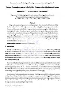
parameters that result from the “Universal axis test” are determined as friction characteristic quantities [12]. For the computation of the characteristic quantities complex mathematic models were implemented [13,14]. The dynamic system has to be stimulated with a special motion profile. To get a deeper understanding of this test, drive signals were sampled during a test (see Fig. 2). Trend curves are provided from the characteristic quantities, if repetitions of single measurements have been made. It is suggested to use the interpretation of these series of measurements as basis for the statusoriented maintenance. -1
x 10
-2
-3 7000
7100
7200
7300
7400
7500
7600
7700
7100
7200
7300
7400
7500
7600
7700
7100
7200
7300
7400
7500
7600
7700
2000
0
-2000 7000 6 x 10 1 Geschwindigkeit
PLC generates an alarm message.
0
-1 7000
Fig. 2. Extract of drive signals during a “Universal axis test” (from above: position, current, velocity). Supplementary, a feature called “Load monitor” is used to collect and analyze the life-cycle loading of the machine axis [12]. 2.2. LoeWe – Life Cycle Oriented Machine Tool
2.1. ePS Network Services The Siemens AG offers with its ePS Network Services a tool that provides amongst other services several tests for the acquisition and documentation of the current machine axis state [11]. This special application is called “Machine Performance” and includes the following tests: y Circularity test, y Following axis test, y Universal axis test. During the tests control internal data is sampled and used for feature extraction. The calculated
One objective within the research project “LoeWe – life cycle orientated machine tool” [15] is to monitor the degradation status of components with functional relevance like the ball screw of the feed axis. The knowledge about the current wear and tear condition shall then be used to calculate the remaining life time of this component. A model based approach is chosen to reach this goal. As input for the model it is suggested to use control integrated signals (drive current and speed) and additional external sensor signals [16]. At this moment, no further public information
about the concrete functionality and achieved results is available. The project is funded by the German Federal Ministry of Education and Research (BMBF) within the framework concept ”Research for Tomorrow’s Production”. 2.3. REACH - Development of a method to improve the reliability and availability of machine tools Within the European Brite / EuRam project REACH (1998-2001) a modular system for the monitoring of machine tool component state should be developed [17,18]. To describe the component behaviour current control internal signals of open CNCs were used. If necessary, external sensors should be integrated into the system. With the aid of long-time tests, it could be shown that the usage of the drive current instead of displacement force signal is sufficient to detect mechanical disturbances [19]. Validation of the realized monitoring system was done at a test bench for two typical feed axis’ failures: y backlash, y pitting on guideways.
development of electronic services for the analysis and prediction of machine health status using enhanced diagnostic algorithms [24]. In this approach data recording is carried out during a specifically designed test-NC-program under defined conditions. The recorded signals used are drive current and rotation speed of axis or spindle drives. To estimate the condition of a feed axis with controlled rotation speed a mathematical linear model of this electromechanical unit was built. From this system of differential equations, which describes the process, characteristic diagnostic features are generated. These features represent the physical parameters static and sliding friction and the moment of inertia. Drive current, rotation speed and acceleration derived from the rotation speed are used as input for the least squares method. This approach is used for parameter identification from an overdetermined set of linear equations [25]. In addition to the diagnostic tests the load profile of the machine tool is continuously logged during normal machine operation. From this load profile experience based statements about the “health state” to be expected can be made. Fig. 4 shows an example of the estimation of the point in time where service activities are expected to be needed [26].
The backlash detection was analysed by building the difference between the direct and the motor encoder [20]. In context of this project a doctoral thesis should be mentioned [21]. A detailed enumeration of analytical methods for the detection of various feed axes disturbances is given there. 2.4. Machine- and Process Diagnostics In an ongoing project at the Institute for Control Engineering of Machine Tools and Manufacturing Units (ISW) in Stuttgart, the usability of control integrated signals for the condition monitoring of feed axes is part of exploration [22]. The project is funded by the VDW Verein Deutscher Werkzeugmaschinenfabriken e.V. With the help of adapted test signals the “Stribeck Curve” is estimated and backlash error of a gear unit and other moveable machine components is detected [23]. 2.5. e-Industrial Services One aspect of the Fraunhofer research project “eIndustrial Services” (2000-2003) was the
Fig. 3. Linear regression of cumulated rotation speed. 3. Monitoring Concept As mentioned in chapter one in the case under consideration the machine tool axes underlay a special load profile that is specific for this kind of machining. The challenge is to develop a monitoring system that has on the one hand a sufficient sensitiveness to detect progressive, position depending deterioration. On the other hand it has to be robust enough to meet the rough manufacturing environment. Last but not least it has to fulfil the
requirement that additional auxiliary process time shall be avoided. 3.1. Premises The grinding machines are mainly implemented in the sector of mass production for the automotive industry and its subcontractors. The machine tools are characterised by a great number of machine axes due to the technology of centerless grinding. A typical axes plan is shown in Fig. 4. The grinding wheel is made up of corundum and mounted on the X1-axis. The weight of a new one is about 400 kg (without mounting device) and will be reduced in consequence of abrasion.
Fig. 4. Axes plan of a MIKROSA centerless grinding machine tool of type KRONOS M.
pre-processing, and data compression is done at the machine tool, storage, analysis, and visualisation is done at the location of the machine manufacturer. This has the advantage that a huge amount of data, even from distributed machine tools at different places, can easily be used for comparative analyses. The aspect of data transmission is left out in this paper. It belongs to the thematic area of information and communication technologies and how to build up a secure IT infrastructure (cf. [27]). 3.3. Axis Test and Life Cycle Data If wear and tear of a feed axis increases the dynamic behaviour of the feed drive system changes. E.g., in consequence of modifications within the tribological system the friction rises and sluggishness occurs. Along with the increased friction the drive current rises too [28]. By moving the axis with constant feed rate along the whole traversing range (both directions) it is possible to detect changes in the dynamical behaviour. During the test drive current, position, and feed are sampled. Fig. 6 exemplifies the sampled position and drive current data of an axis test. The feed signal is used for an automated detection of the both intervals, where the positive respectively negative axis motion is at a constant level. The phases of acceleration are masked because they would falsify the analysis.
The machine tools are equipped with an open CNC system of type SINUMERIK 840D made by Siemens. This open CNC architecture enables data acquisition of control internal sensor signals and machine data via OPC (OLE for Process Control). 3.2. Structure of the Monitoring System The proposed monitoring system includes the following principal tasks: y data logging, y signal pre-processing (sensor signals only), y data compression, y data transmission, y storage of data, and y analysis of data. Fig. 5 presents the schematic structure of the system. Regarding the different tasks, a decentralised architecture was chosen. While data logging, signal
Fig. 6. Axis position (left) and drive current (right). Auxiliary data, containing information about the life cycle of the machine tool is logged continuously. Amongst others the alarm-log history and information about executed maintenance activities. These data support failure analysis because they represent the order of events that have happened during machining operation before a failure occurs [29].
Fig. 5. Global structure of the monitoring system. 3.4. Pre-Processing The following statistical moments are calculated from the drive current signal and are used to generate key indicators for condition monitoring: y mean value, y variance, y skewness. The meaning of significant changes of mean value and variance is evident. Drive current is proportional to the driving torque. Therefore trend monitoring of the mean value indicates operation difficulties of the feed axis. The variance of the signal characterises the smoothness of the system.
Fig. 7 and 8 show exemplarily the chronological development of position depending variance and mean value of feed drive current signals. The traversing direction is from software limit switch plus to minus. The monitored axis is the X1-axis (cp. Fig. 4) of a KRONOS L. The trends in the characteristic values are easy to see. More power is needed to traverse the feed axis and the variance is rising. The machine is still working and no maintenance activities were necessary until now. This example shows the sensitiveness of the characteristic values. -2.30E+03 503 mm
-2.50E+03
483 mm -2.70E+03
463 mm
6.50E+03
443 mm
6.00E+03
423 mm
5.50E+03
403 mm
5.00E+03
383 mm
4.50E+03
363 mm
09 .1 1. 05
02 .1 1. 05
26 .1 0. 05
19 .1 0. 05
12 .1 0. 05
4.00E+03
Fig. 7. Chronological development of position depending variance of feed drive current signal.
423 mm 403 mm
-3.10E+03
383 mm
-3.30E+03
363 mm
-3.50E+03 09 .1 1. 05
483 mm
7.00E+03
02 .1 1. 05
7.50E+03
443 mm
-2.90E+03
26 .1 0. 05
503 mm
463 mm
19 .1 0. 05
8.00E+03
12 .1 0. 05
8.50E+03
Fig. 8. Chronological development of position depending mean value of feed drive current signal. The skewness defines at which side of the mean value there are more data. It can be used to detect beginning failures that depend on the direction of
traversing. As mentioned before the deterioration process does not proceed homogeneously at all positions on the axis. For this reason the analysis of the signal is divided into small windows. Every window belongs to a certain position on the axis. To avoid additional auxiliary process time the axis test is combined with a periodically recurring traversing of the axes that are used to disperse the lubricant on the guidance. 3.3. Data Management To detect trends in the chronological history of the stored characteristic values, the existence of an initial state is required. The computed characteristic values indicate the “good” health state of a feed axis and provide the basis for trend detection. XML (eXtensible Markup Language) was chosen as data interface between the different components of the monitoring system. XML is a universal data exchange format that can be used for machine to machine communication. In the presented work the XML-logfiles are parsed by a XSLT-processor. The processor generates files in SQL-format (Structured Query Language) to import the data into a relational database (see Fig. 7). The database scheme maps the relations between the data, the components and the individual machine tool.
monitoring of feed axes it is possible to detect trends of slowly progressing changes of the dynamic system. Information about the machine tool’s load history that is additionally logged during the machine tool’s life cycle can be used to support searching for failure causes. The database based approach enables comparative analyses and long term investigations. With the development of new axis tests and algorithms for the analysis further key indicators for degradation monitoring of feed axes will be provided. The implementation of intelligent machine tool components that are able to analyse and store their wear status will enlarge the field of condition monitoring applications. Acknowledgement The presented work is part of the research project DYNAPRO which is funded by “Stiftung Deutsche Industrieforschung”. It was done in cooperation with Studer Mikrosa GmbH. The Studer Mikrosa GmbH is manufacturer of centerless external cylindrical grinding machine tools. Fraunhofer Institute for Production Systems and Design Technology is partner of the EU-funded FP6 Innovative Production Machines and Systems (I*PROMS) Network of Excellence. References
DTD
[1] [2] XML
XML XML
XSLTProcessor
SQL
XML XML
[3] XSL
[4]
Fig. 7. Data transformation from XML to SQL. Visualisation of the data is provided by predefined reports. It is possible to have a look at the stored information from different views and within arbitrary time intervals.
[5]
[6] [7]
4. Conclusion and Outlook Using the proposed method for the condition
[8]
N.N.: KRONOS - Centreless surface cylindrical grinding. Product brochure, 2005. N.N.: www.ima.uni-stuttgart.de/dichtungstechnik/ aktuelle_projekte/wzm/wzm.en.html. Institute of Machine Components, University of Stuttgart, 2002. Jansen, M.: Abstreifer für Werkzeugmaschinenführungen. Dissertation, Universität Stuttgart, URN: urn:nbn:de:bsz:93-opus-24403, URL: http://elib.unistuttgart.de/opus/volltexte/2005/2440/, 2005. Walter, K.-D.: Wireless für Präventiv-Aufgaben. In: Computer & Automation, 01 – 2006, pp. 36-39. Lee, J. et al.: An integrated platform for diagnostics, prognostics and maintenance optimization, Proceedings of the Intelligent Maintenance Systems 2004, July 15-27, 2004-Arles, France. Lee, J, Ni, J.: Smart Prediction to Prevent Downtime. In: INNOVATION, Vol. 4 No. 3, 2004, pp. 41-42. Djurdjanovic, D.; Lee, J.; Ni, J.: Watchdog Agent – an infotronics-based prognostics approach for product performance degradation assessment and prediction. In: Advanced Engineering Informatics, Volume 17, Issues 3-4, July-October 2003, pp. 109-125. Grudzien, W.; Seliger, G.: Life Cycle Unit in Product
[9]
[10]
[11]
[12] [13]
[14] [15] [16]
[17]
[18]
[19] [20]
[21] [22]
[23]
Life Cycle – Tool for improved maintenance, repair and recycling. In: Proc. 33rd CIRP Intern. Sem. Manufacturing Syst., 2001, pp. 121-125. Hirschmann, J.: Fault detection and diagnosis of the electromechanical drive units in the automation technology. Conference Proceedings: EManufacturing and E-Business Integration, Milwaukee, Wisconsin, USA, September 9-11, 2002, pp. 179-181. Middendorf, A. et al.: Life-cycle information units for monitoring and identification of product use conditions. Proceedings: Global Conference on Sustainable Product Development and Life Cycle Engineering 2004, September 29 - October 1, 2004, Berlin, pp. 91-96. N.N.: More Productive with Telemaintenance Condition Monitoring reduces plant downtimes. In: motion world - Systems and Solutions for Machines and Plants, September 2005, pp. 18-19. N.N.: ePS Network Services 3.2 - Description of Functions. 9. August 2004. N.N.: Vorhandene Technologie noch besser nutzen – Experteninterview zu aktuellen Entwicklungen im Bereich des Condition Monitoring. In: elektro Automation 7/2005, pp. 16-21. Barth, R.: Produktiver mit >Condition Monitoring