a pre-calibrated off-the-shelf camera and a set of radio-opaque rods suitable for ... guided treatments are used for precision treatment of rigid tu- mors (targets).
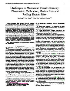
MONOCULAR VISUAL PATIENT MONITORING FOR FRAMELESS STEREOTAXY Amit Kale, Manivannan Sundarapandian, Vipin Gupta Siemens Information Systems Limited, No.84 Keonics Electronics City, Bangalore ABSTRACT In this paper, we propose a low cost, robust vision based system for monitoring patient movements during stereotactic radiotherapy: the Monocular Visual Patient Movement Monitoring (MVPM) System. The system consists of a light weight mouth bite with dual fiducial system used for position tracking. One set of fiducials consist of easy-to-detect checkerboard whose 3D position can be tracked using a pre-calibrated off-the-shelf camera and a set of radio-opaque rods suitable for X-ray imaging. We describe the associated workflow steps for using the system during planning and treatment phases. Also we report experimental results for tracking accuracy using a in-house phantom.
1. INTRODUCTION In external beam radiation therapy (EBRT), stereotactically guided treatments are used for precision treatment of rigid tumors (targets). Here the target position is connected to an external coordinate system; and using mechanical frames, the rigid correspondence between the target and the coordinate system is maintained throughout the treatment(see Figure 1). However,the mechanical frames cause lots of pain and inconvenience to the patient. Hence, the modern systems aim for frameless stereotaxy. For example, [1] uses a mouth bite for frameless stereotaxy for intracranial patients. The mouthbite has fiducials that are detected in the planning CT and later tracked using IR cameras mounted on the ceiling. However, as the distance between the camera and the mouthbite increases, the positioning accuracy reduces. While we are not aware of the complete system that they have, it is important to point out that IR cameras are more expensive than visual ones. A potential marker-free solution to the problem is to get some fiducials automatically from the patient e.g. For cranial tumors for instance the face of the patient can be tracked and using multiframe structure from motion we can recover the 3D motion of the patients face [2]. While this has the desirable property that no extraneous equipment needs to be attached to the patient, the downside is that it depends on the availability of a sufficient number of fiducials on the patient. At least for the case of faces, this number can be pretty small as a result of which the accuracy of 3D motion estimation is
Fig. 1. Relocatable Frame used in Stereotactic radiotherapy. This can be very cumbersome for the patient rather low. Since we are looking at really high level of accuracy in estimating 3D patient motion, we need to have extremely reliable tracking and 3D reconstruction. As a result we have to opt for a fiducial tracking strategy. In recent times, the developments in computer vision have spurred the development of cheap cameras and hardware for different applications. Specifically many algorithms have come up which can provide for rapid and accurate visual tracking and 3D reconstruction of scenes. We plan to leverage some of these developments to provide less cumbersome approach to keep track of the patient during treatment at a lower cost. We propose the use of a vision based tracking system for stereotactic surgery: the Monocular Visual Patient Movement Monitoring (MVPM) System. The features of our system are 1. Mouth bite with dual fiducial system used for position tracking. 2. Camera based tracking system during treatment. 3. Fiducial rods to register the stereotactic (STX) coordinates with planning image volume
(a)
(b)
Fig. 2. Frameless tracking system from Varian(a)Mouthbite with IR LEDS (b)Patient placement 4. Checker board (corners) used to track target movement during treatment.
2. Checkerboard Coordinate System (CHCS) 3. Stereotactic Coordinate System (STS)
5. Camera placement close to the patient for better accuracy. In subsequent sections we describe the system components, workflow and experimental results obtained using an in-house phantom. 2. SYSTEM OVERVIEW The MVPM system addresses the problem of monitoring patient position when he/she is undergoing stereotactic radiotherapy for treatment of intracranial tumors. The aim is to have the treatment with minimum vexation to the patient at low cost. The method consists of 3D-tracking of a planar target using a single camera. The tumor is assumed to be at a fixed offset from this target. We design a target which is inverted hut shaped made of acrylic plates. We devised two sets of fiducials, present on the target. One set consists of solder wires which are visible in CT slices. They are buried at four different orientations with respect to the sides of the plate on the outer side of the plate (see Figure 3). We will refer to this fiducial set as radio visible CT fiducials (RVCTF). The second set consists of checkerboard pattern pasted on the outer side of the plates. We will refer to this fiducial set as Camera Fiducials(CF). In order to achieve a higher accuracy using off-theshelf visual cameras, we deploy the camera on an accessory which can be attached to the treatment table as required (see Figure 4). By placing the camera close to the target (around 40 cm) good accuracy can be achieved of within ±0.5mm can be achieved which is sufficient, given that the slice spacing in conventional CT is around 1mm We also have 4 different coordinate systems in the system 1. Camera Coordinate System (CCS)
4. Patient/CT Coordinate System (PCS) The need for two sets of fiducials can be motivated as follows: The tumor along with the RVCTF are visible in CT while CF is visible in camera. Using the RVCTF images in CT which will appear as dots (see Figure 3) and by knowing the positions and orientations of the rods with respect to some fixed origin on the acrylic plate, we can derive the Euclidean transformation between the STS and PCS. This further allows us to physically measure the tumor location with respect to this STS origin as well. During stereotactic radiotherapy it is imperative that the patient position be maintained accurately. This further implies that the STS origin be absolutely fixed. There exists a fixed and known offset between the CHCS origin and the STS origin. Thus if we can track the motion of the CHCS origin then the motion of the tumor can be estimated accurately. However this motion will be with respect to the CCS. By pre-computed transformation between the CCS and CHCS, CHCS and STS and finally STS and PCS we estimate the tumor movement in the PCS.(Note that tumor displacement in the PCS is what is of ultimate interest to the doctor.) 2.1. Workflow 2.1.1. Planning At first the teeth impression of patient is taken by having the patient bite on acrylic material which will assume the specific teeth profile specific to him. The hut is then attached to this mouth-bite(customized for the patient). The patient is then immobilized while holding the mouth bite (with standard STX frame). A CT scan of patient is taken. On CT images the oncologist identifies the tumor center Xtu|CT . Note that, we use CT as planning image volume, because of its high image
(a)
Fig. 4. Placement of the camera as a stereotactic accessory. The working distance between the target and the camera is around 40 cm
(b)
resolution. However, one could use image volume from any modality. The oncologist also identifies the rod intersections (circular marks) in various CT Slices. Planning System computes transformation between STX and CT (Rsts|ct , tsts|ct ) (For details see Section 2.2)
2.1.2. Treatment
(c)
The patient holds the mouth bite and immobilized with standard STX frame (to reproduce the planning setup) and a camera image is captured. With lasers ON, origin of the hut is aligned to machine isocenter. (R0 , t0 ) are computed which denote the offset of the STX coordinate system with the camera in the alignment stage. The standard STX frame is then removed. Now the patient holds only mouth bite and is monitored by the camera. Images are acquired from camera periodically (10 frames/sec). For each frame, Positioning system computes (Rn , tn ) The tumor displacement is finally computed as (Section 2.3). ∆X
= RST X|CT (∆RXtu|ST X + ∆t) + tST X|CT (1) − (RST X|CT Xtu|ST X + +tST X|CT ) = RST X|CT (∆RXtu|ST X + ∆t − Xtu|ST X )
(c) Fig. 3. Schematic Image of Planar target with dual fiducials used in the MVPM(a)Back of hut with layout of rods(b)Front side with printed checkerboard (c)Actual hut prototype (d) CT Image of the hut cross-section
Treatment is stopped ∆X has moved beyond an acceptable tolerance.
2.2. Calibration between the PCS and the STS
In the stereotactic coordinate system, given the location of the start points of the fiducial rods p and their slope v, we can describe each point on the fiducial rod as p + λv. Assume that the STS and PCS are related by the following Euclidean transformation Xsts = Rsts|ct Xct +tsts|ct . Substituting Xsts = p + λv we get p + λv = Rsts|ct Xct + tsts|ct . Note that given the rod intersections in CT, the value of λ needs to be jointly estimated together with Rsts|ct , tsts|ct . For the sake of brevity we drop the subscripts on (Rsts|ct , tsts|ct ): RX + t − λv = p
r11 r21 r31
r12 r22 r32
r13 x r23 y + t − λv = p r33 z
x 0 0 x 0 0
0 0 x
y 0 0
0 y 0
0 0 y
z 0 0
0 z 0
0 0 z
1 0 0 0 1 0 0 0 1
−vx −vy −vz
The number of unknowns in this equation is 13 while each data point gives 3 equations. Note however that, the rotation matrix has fewer degrees of freedom. Specifically given two columns of the rotation matrix, the third is simply a cross product of the first two. This reduces the number of unknowns to 10, simplifying the equation to:
x 0 0 x 0 0
0 0 x
y 0 0
0 y 0
0 0 y
1 0 0 −vx 0 1 0 −vy 0 0 1 −vz
r11 r12 r13 r21 r22 r23 t λ
=p
Thus a minimum of 4 point correspondences in each slice will be required to get the LS solution for the unknowns. Denoting by Ai the data matrix for each point i, the system of equations can be written as:
(5)
pm
(6)
(7) (8)
Knowing y the rotation matrix can be completed by comput ing the cross product of the first and second triplets in y. 2.3. Transformation between checkerboard corner and CT =p The tumor center in the camera coordinate system is related to the tumor center in the STX coordinate system as: Xtu|0|cam = R0 Xtu|ST X0 + t0 (9) Xtu|n|cam = Rn Xtu|ST Xn + tn
(10)
Here the subscript 0 refers to the reference position and n refers to the nth frame It is now easy to see that the tumor coordinates with respect to the STX coordinate system at frame 0 is given by: Xtu|n|ST X0 = ∆RXtu|ST X + ∆twhere ∆R =
p1 p2 .. .
(4)
r11 r12 r13 r21 y= r22 r23 t λ Ay = p y = (AT A)−1 AT P
(3)
r11 r12 r13 r21 r22 r23 r31 r32 r33 t λ
Am
p=
(2)
A=
A1 A2 .. .
R0−1 Rn , ∆t
=
R0−1 (tn
− t0 )
(11) (12)
Finally the tumor location and displacement in the CT coordinate system can be obtained as: Xtu|n|CT
= RST X|CT Xtu|n|ST X0 + tST X|CT (13) = RST X|CT (∆RXtu|ST X + ∆t) + tST X|CT
∆X
= RST X|CT (∆RXtu|ST X + ∆t) + tST X|CT − (RST X|CT Xtu|ST X + +tST X|CT ) = RST X|CT (∆RXtu|ST X + ∆t − Xtu|ST X )
2.4. Camera Processing The steps involved in obtaining the 3D position of the checkerboard is to find a set of 4 or more corresponding points on the
planar checkerboard in the image plane as well as in the world plane. In order to obtain the corners in the image plane, we employ two algorithms: one is a checkerboard corner detector followed by Harris based refiner [3] which gives corners with sub-pixel accuracy. The checkerboard pattern is detected in first step, followed by checkerboard segmentation. The corners are finally detected in binarized checkerboard using sample point matching. The 3D locations of the corners are known with reference to an arbitrarily chosen point on the checkerboard. Given this point correspondence and the calibration data A obtained by using the method described in [4], we can obtain the 3D coordinates of the origin as described below: 2.4.1. Estimation of Motion Without loss of generality, we assume that the model plane is on Z = 0 of the checkerboard coordinate system. Let us denote by ri the ith column of the rotation matrix. Then we have X u [ ] Y s v = K r1 r2 r3 t 0 (14) 1 1 [ ] X = K r1 r2 t Y (15) 1 X = H Y (16) 1 where H denotes a homography. Given the correspondence of a minimum of 4 points between the checkerboard points and their camera images H can be easily computed using the direct linear transformation. Finally given the intrinsics of the camera K we can obtain the rotation R and t as: [r1 r2 t] = K −1 H R = [r1 r2 r1 × r2]
(17) (18)
3. RESULTS In order to validate our algorithm, we used a jig in which the motion of an attached board can be set precisely in x y and z directions. This jig was fabricated to provide an offset of ±10cm with 1mm precision in each direction. Two views of the jig are shown in Figure 5. The jig has three knobs which can be manually controlled to set the desired position offset, and keep it locked. The spirit-level in its base is used to ensure that there is no tilt in the table, where the experiment is done. The hut was fabricated without the mouth bite so that it can be placed on the jig. The images acquired are of resolution 640 x 480. Note that for the actual setup we expect
Fig. 5. Pictures of Jig used for validation of the algorithm. to use a higher camera resolution which will make our corner and motion estimates to be that much more accurate as compared to the present values. The estimation results using our algorithm when giving known displacement offsets (in steps of 1mm) in x y and z directions are shown in Figure 6. In the figure, we show the actual estimated displacement in x,y,z . We model the displacement as a Gaussian random variable whose mean and variance can be estimated by the sample mean and variance of the observed displacements. The mean estimated displacement in the respective cases was 0.9672, 0.9824, 0.9682 mm respectively with a standard deviation of error of 0.1507, 0.14360.2368 mm respectively. By using a single camera, we achieved a high accuracy the x, y, and z directions, for the camera placement which we have planned. 4. CONCLUSIONS AND FUTURE STEPS In this work, we described a novel approach of 3D tracking/monitoring of the patient using single camera. In future, we would go for three phases of clinical validation; in phase 1 we would use this jig on a LINAC treatment table, with the camera positioned as in the MVPM configuration. The goal is to monitor the positional offsets under clinical condition. In phase 2, we would go for dry runs with actual pa-
tients (meaning without any radiation). Phase 3 will validate the performance with actual patients while undergoing treatments. Also currently we are exploring ways to extend the method for tracking non-rigid body parts such the thorax and abdomen using techniques described in [5]. 5. REFERENCES [1] Sanford Wagner, “Optical tracking technology in stereotactic radiation therapy,” Medical Dosimetry, vol. 32, no. 2, pp. 111–120, 2007. [2] http://www.visionrt.com/page 154.html, ,” . [3] C. Harris and M. Stephens, “A combined corner and edge detector,” Proceedings of the 4th Alvey Vision Conference, pp. 147–151, 1988.
(a)
[4] R. Hartley and A.Zissermann, Multiple View Geometry in Computer Vision, Cambridge University Press, 2000. [5] M Salzmann, J Pilet, and S Ilic, “Surface deformation models for nonrigid 3d shape recovery,” IEEE Transactions on Pattern Analysis and Machine Intelligence, 2007.
(b)
(c) Fig. 6. Accuracy of the displacement produced by the camera based tracking in (a)x (b) y and (c) z directions.