The points Q(qx|qy|0), R(rx|ry|0) denote the perpendicular bases from the augmented device position ... GC the determination of five DOF are uniquely done.
Monoscopic 6DOF Detection using a Laser Pointer Elmar Bomberg, Marc Erich Latoschik AI & VR Lab University of Bielefeld PO 100 131 33501 Bielefeld Germany Tel.: +49 (0)521 106 2923 Fax: +49 (0)521 106 2962 E-Mail: {ebomberg—marcl}@techfak.uni-bielefeld.de Abstract: This article illustrates, through the use of a simple laser pointer device and a camera, the detection of 6 degrees of freedom (DOF) in Virtual Environment interactions. For this purpose, the laser pointer device is augmented by a diffraction grating to project a unique laser grid onto the projection planes used in projection-based immersive VR setups. The distortion of the projected grid is then used to calculate the additional degrees of freedom as required for human-computer interaction purposes. Keywords: laser pointer, 6DOF detection, interaction
1
Introduction and Related Work
Interaction in Virtual Environments requires information about position and orientation of specific interaction tools or body parts of users. This information is commonly provided by various tracking devices based on mechanical, electromagnetic, ultra-sonic, inertial, gyroscopic, or optical principles. Besides qualitative aspects of resolution, data-rate and accuracy, these devices in general differ in their hardware setup which includes the control behavior (active or passive) and the use of active or passive markers or sensors. For example, several successful optical tracking systems nowadays use reflective infrared (IR) markers lit by IR-LEDs that are captured by IRcameras to track uniquely arranged sensor targets. An alternative approach uses active sensors which emit light and save the need of an additional lighting device but require additional power sources, mounts and/or cabling. Here, laser pointers present a lightweight and low-cost solution for simple interaction purposes where full body captures are not required and simple tool based operations like select and dragand-drop are sufficient. Unfortunately, common laser pointers only provide 2DOF as their emitted
laser beam intersects a plane generating a single laser point. In this article, we illustrate a modified laser pointer capable of providing 6DOF while preserving all the favorable properties.
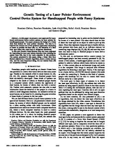
Figure 1: Scheme of the direct interaction with the laser-pointer device augmented by a cross diffraction grating
Several approaches use custom-built laser devices that project more than one laser spot on one or more projection screens to provide additional DOF. Matveyev [MG03] proposes a multiple-point technique with an infrared laser-based interaction device. It projects three infrared laser spots on a projection screen using one primary and two auxiliary laser-beams. The first auxiliary beam has a fixed angle of divergence, whereas the other can change its deviation angle mechanically relative to the primary beam. With this technique the interaction device has 5DOF, two for movement in the x- and y- direction, one for rotation in the x,y-plane, one for the shift along the z-axis and one for mouse emulation purposes. The Hedgehog, proposed by Vorozcovs et. al [VHS05], provides 6DOF in a fully-enclosed VR display. The device consists of 17 laser diodes with 645nm wavelength in a symmetrical hemispherical arrangement, where each laser diode is placed in a 45 degree angle from each other and is individually controlled by a PIC micro controller through a serial interface. The fullyenclosed VR display has at least one camera for each projection screen to track the laser spot positions produced by the Hedgehog. The proposed technique allows to determine the 6DOF with an angular resolution of 0.01 degrees RMS and position resolution of 0.2 mm RMS. 1.1
Discussion
The approach proposed by Matveyev and G¨obels [MG03] approach has a few disadvantages:
• The additional DOF decrease when the number of the three available laser spots on the projection screen drops. • The laser spot distance required for depth calculation has to be very small to allow a high interaction radius. • A high camera resolution and precise subpixel estimation is required. Vorozcovs et. al [VHS05] propose a technique allowing a highly-accurate detection of 6DOF at a reasonable update rate. However, this technique ideally requires multiple projection screens and a rather complex hardware installation. The technique proposed in this work, illustrated in Figure 1, involves a laser pointer based tracking system that determines 6DOF relative to a single projection based immersive VR-setup while overcoming some of the limitations found in [MG03]. In addition, the hardware costs for the laser pointer interaction device and the digital camera are very low in comparison with other optical tracking systems.
2 2.1
Concept Augmented Device
The augmented device consists primarily of three components: A customary green laser pointer, a cross diffraction grating and a custom-built mount. The custom-built mount allows for the attachment and adjustment of the cross diffraction grating orthogonal to the laser pointer. An overview of the custom-built mount is illustrated in Figure 2. In combination the components project a regular laser point grid onto a planar screen, if the device is oriented perpendicularly. The choice of the laser output power and the cross diffraction grating depends on the constraint, that either the whole or a part of the projected grid should utilize the entire projection area with a maximum number of projected laser points. In this case the complete resolution of the camera can be used to determine the 6DOF. Nevertheless the output power of the laser pointer still has to fulfill laser safety regulations. The physical parameters of the device, such as the laser output power and the wavelength determine the characteristics of the projected grid, where the intensity decrease gaussian-shaped from the center order to higher orders. The laser pointer’s wavelength determines the angle of divergence between the laser beams as well as the size of the projected laser point grid on the projection screen. For our augmented device we are using a holographic cross diffraction grating, commercially used for entertainment purposes such as laser shows. This grating has a groove period of approximately 6055.77 nm and a groove density of 165.1 grooves per millimeter. In combination with
a laser pointer of 532 nm wavelength, the angle of divergence between the laser beams of zero and first order is approximately 5.03 degrees. This green laser pointer has been chosen, because there exists a close dependency between the emitting device (the laser device) and the sensor (the camera). In our case a 1CCD-Chip bayer camera is used for its greater sensitivity for the color green, as it contains two times more green than red and blue pixels. For laser safety reasons the output power of the augmented laser pointer is lower than 1 mW. It is possible to use a laser pointer with an output power of 4 mW, because the cross diffraction grating diminishes the output power in the zero order to a quarter of its former value. To maintain the immersion of the VR setup, it is possible to use an IR laser pointer in conjunction with an IR-camera. To mount the cross diffraction grating on the laser pointer a special mount has been developed. Figure 2 shows the assembly of the grating mount.
Figure 2: Grating Mount The mount consists of a separate aluminum housing with apertures for the laser beam to encapsulate the diffraction grating. This aluminum housing rests on a hard rubber layer and allows for adjustment of the encapsulated diffraction grating at two axes. The center cross of the projected grid may not be bent and can be calibrated in comparison with an orthogonal line cross on a sheet of paper. 2.2
Camera Installation
In order to detect the projected laser points, we are using a 1CCD-Chip digital firewire camera with a resolution of 640x480 and a framerate of 30 fps. The camera provides non-interpolated color images, and thus allows a more precise image processing. Figure 3 shows the camera setup for a rear projection screen. The camera is mounted below the video projector and observes the projection screen via the projection mirror. This position provides an ideal image of the projection screen with the minimum of perspective distortion (see [OS02]). It is possible to install the camera on the viewers side, but this requires more complex image processing as the projection reaches maximum intensity seen from this position. Furthermore the camera position will constrain the viewers’ movements to prevent occlusions.
Figure 3: Setup of the laser-pointer based tracking system.
2.3
Image Processing and Calibration
The laser point detection in our implementation is based on a simple threshold operation to identify bright pixels in the color of the laser pointer wavelength. The subpixel-precise position is calculated by an intensity weighted sum of the pixels belonging to one laser spot as described in [OS02]. In higher orders of the laser point grid the subpixel-precision decreases, because in that case the laser spot size corresponds to only one pixel of the camera image. For the calculation of the real 2D laser point position in projection screen coordinates, the radial and the perspective distortion have to be measured beforehand. The radial distortion parameters are determined by using a planar chessboard pattern. To calculate the perspective transformation, a projective planar transformation named homography is computed [HZ03] that transforms the 2D undistorted (radial) camera image coordinates into projection screen coordinates. For this purpose four measured undistorted point coordinates in the camera image and their corresponding projection screen coordinates are determined. These four points are determined by projecting a standard laser pointer into the four corners of the projection screen and their subpixel-precise laser point detection according to [VHS05]. Afterwards these coordinates are transformed in radial undistorted coordinates. The corresponding projection screen coordinates are measured manually. We have chosen the upper left corner of the projection screen as point of origin of the projection screen coordinate system. 2.4
Laser Point Grid Calculation
To determine the 6DOF one has to calculate four basic steps: 1. Calculate the physical laser point coordinates of the projected grid, when the augmented
device is oriented orthogonally to the projection screen. 2. Assign the detected laser point positions to a 2D order (m, n) of the grid model (see Section 2.5) . 3. Calculate the laser beam triangles for certain laser points (see Section 2.6). 4. Compute the 6DOF of the augmented device (see Section 2.7). For the calculation of the projected grid laser point coordinates, the laser pointer wavelength λ, the diffraction grating groove period b, the distance to the projection screen l and the 2D order positions (m, n), where m, n ∈ Z, are needed. In general the order positions in physics have positive values. For the calculation of the laser point grid, order position values have been extended to negative values, and represent the grid model in this work. This allows the calculation of unique positions for each order, where the zero order marks the center of origin in the laser point grid coordinate system. The physical order position (x, y), where x, y ∈ R, can be calculated by the following formulas, in which r denotes the distance between the (0, 0)-order and the arbitrary order (m, n): √ l n2 + m2 λ r= q √ b 2 2λ 2 ) 1 − ( n +m b x=r
n 1 q |n| 1 + ( m )2
(1)
(2)
n
y=r
( mn )
n q |n| 1 + ( m )2
(3)
n
If n = 0 then: x=0 m y= r |m|
(4) (5)
Figure 4 shows one example for the calculation of the projected laser point grid for the augmented device parameters (wavelength, groove period, distance) . This illustrates that the projected laser points of adjacent orders in horizontal and vertical direction are not equidistant. The grid positions are the bases for calculating the angles of divergence between two orders, which in turn is required for the 6DOF determination.
Figure 4: Calculation of the laser point positions for a 2D cross diffraction grating. λ = 532nm, b = 6055.77nm, l = 1000m (theoretical distance), Order (−3, −3) to (3, 3) 2.5
Grid Mapping Heuristic
The detected laser points have to be mapped to the 2D orders (m, n) of the grid model. This grid assignment is not unique because of the laser point grids rotational symmetry in the projection plane. Consequently the mapping of the grid model changes with every quarter turn. For the complete grid assignment, the following steps are processed: 1. Assignment of the zero order (0,0) to the grid model, which can be identified through the laser point pixel size. 2. Determination and validation of the 3x3 neighborhood surrounding the zero order (0,0) and assignment to the grid model. 3. If the first 3x3 neighborhood is neither complete or correct, the determination and validation of the 3x3 neighborhood is processed on the previously found neighbors surrounding the zero order, until a valid neighborhood has been found. 4. Mapping of the orders based on the first assigned orders using the laser beam triangle calculation (see section 2.6). To find the 3x3 neighborhood of the order under examination, the search method illustrated in Figure 5 is applied using the following notation: NC is the center of the neighborhood, NN
are the nearest neighbors, ON are the opposite neighbors, FoundLaserPointsList is the list of all detected laser points and FoundNeighborsList denotes the found neighbors. In the first step of the neighborhood search the examined order, in this case the center of the neighborhood NC is deleted from the FoundLaserPointsList (see Figure 5 A). Afterwards following steps are applied four times (see Figure 5 B-F): 1. Find the nearest laser point NN next to the examined order NC in the FoundLaserPointList. 2. Find the nearest laser point ON opposite to the previously found laser point NN relative to the examined order NC and add NN and ON to the FoundNeighborsList. 3. Delete all laser points from the FoundLaserPointsList, which approximately lie on the straight line with the two previously found laser points NN and ON.
Figure 5: Scheme for 3x3 neighborhood search method
The found laser points in the FoundNeighborsList are validated afterwards, by testing if they belong to a 4-sided polygon surrounding the examined order. The valid 3x3 neighborhood is assigned to the grid model. This first mapping builds the base for the assignment of the remaining laser points found and allows to predict the grid laser point positions by using the laser beam triangle calculation in section 2.6. These predicted positions are compared with the matching grid laser points and assigned to the grid model if they are approximately equal. 2.6
Laser beam triangle calculation
The grid laser points assigned to the grid model provide additional information needed to calculate the angles of divergence between two arbitrary orders. At least five laser point positions of the grid model are necessary to calculate the 6DOF. These five points have to lie on two straight lines, as each described by three laser point positions. These straight lines have to intersect in one point
as shown in Figure 8. Each straight line in conjunction with the position of the augmented device (AD) composes a triangle and will be denoted as laser beam triangle. Figure 6 shows such a laser beam triangle with the laser points P1 , P2 , P3 , the augmented device AD, the laser beam distances b1 ,c,b2 , the laser point distances a1 , a2 and the angles of divergence α1 , α2 .
Figure 6: Scheme of the laser beam triangle calculation
All parameters of the laser beam triangle can be calculated by the distances a1 and a2 , and the known angles α1 and α2 . Some trigonometric relationships lead to following equation: a1 b1 sin (α1 ) = a2 b2 sin (α2 )
(6)
After the application of the law of cosine we get: (a1 + a2 )2 = b21 + b22 − 2b1 b2 cos (α1 + α2 )
(7)
Equation 6 solved to b2 and substituted in equation 7: 2
(a1 + a2 )
= b21 +
�
a2 b1 sin (α1 ) a1 sin (α2 )
�2
− 2b1
�
� a2 b1 sin (α1 ) cos (α1 + α2 ) a1 sin (α2 )
(8)
Solving the quadratic equation with the assumption that a1 , a2 ∈ R+ and α1 , α2 ∈ [0, 90] b1 = r
a1 (a1 + a2 )
1) a21 − 2 cos (α1 + α2 ) a1 a2 sin(α sin(α2 )
+ a22
�
� sin(α1 ) 2 sin(α2 )
(9)
In a similar way the distance b2 can be calculated. The other parameters of the laser beam triangle γ1 , γ2 , β1 , β2 , c, h, ah1 , ah2 can be computed by simple trigonometric relationships.
2.7
6DOF Calculation
The computation of the 3D position and orientation of the augmented device is illustrated in Figure 7 and 8. In this figures the five projection laser points are denoted as A(ax |ay |0), B(bx |by |0), C(cx |cy |0), D(dx |dy |0), E(ex |ey |0).
Figure 7: 3D-scheme for 6DOF Calculation of the augmented device
The points Q(qx |qy |0), R(rx |ry |0) denote the perpendicular bases from the augmented device position G(gx |gy |gz ) to the straight lines AB and DE. With the five laser point positions the dis− → − → −→ −→ tances |AC|, |CB| and |DC|, |CE| can be determined. The angles of divergence ∢ (DGC), ∢ (CGE), ∢ (AGC), ∢ (CGB) can be computed from the known 2D-orders (m, n) of the laser points. This information allows the calculations of the laser beam triangles (AGB) and (DGE). To get the perpendicular base S(sx |sy |0) from G to the projection plane, the intersection of following linear equations is computed: �− � → − g1 : → x = 0Q + λ1 − n→ (10) AB �− � → − → g2 : → x = 0R + λ2 − n− (11) DE
−ABy −DEy → DE with the normal vectors − n→ n− ABx and − DE = AB = x 0 0
Figure 8: 2D-scheme for 6DOF Calculation of the augmented device
So the intersection point S can be computed:
S=
qy nDEx −ry nDEx −qx nDEy +rx nDEy nABx nDEy −nDEx nABy qy nDEx −ry nDEx −qx nDEy +rx nDEy qy + nABy nABx nDEy −nDEx nABy
qx + nABx
0
(12)
The x and y coordinates of the augmented device are given by sx and sy , where the z coordinate is − → given by the length |SG|: − → |SG| =
q
−→ − → |AG|2 − |SA|2
(13)
The 3D position of the augmented device G is:
sx − → − → − → 0G = 0S + SG = sy |SG|
(14)
−→ The direction vector of the pointing beam GC is given by: −→ − → − → GC = 0G − 0C
(15)
−→ − → With 0G and GC the determination of five DOF are uniquely done. The last DOF is approximated by the rotation angle between the straight line of the (m,0)-orders and the x-axis. Because of the rotation symmetry, one can only determine the rotation angle between 0 and 90 degree. Higher rotation angles can be computed by continuous tracking of the laser point grid rotation.
2.8
Conclusion
We have presented an inexpensive new active optical tracking technique, to determine 6DOF relative to a single projection screen. The device’s 6DOF (five absolute and one relative) provide interaction with a virtual environment in an intuitively direct manner. First tests reveal that the accuracy of the 6DOF determination decreases stepwise with the number of detected laser points belonging to one laser beam triangle. To improve the accuracy, a grayscale firewire camera with a higher resolution could enhance the subpixel-precise laser point detection. Furthermore, a laser pointer with a higher laser output power, and a diffraction grating with a smaller groove period to increase the angle of divergence between the orders could also improve the laser point detection. To support multiple devices more than one grayscale camera with wavelength bandpass filters and laser pointers with different wavelengths can be used. Another alternative is a time-division multiplexing technique proposed by Pavlovych and Stuerzlinger [PS04]. In future work, a Kalman filter [Kal60] for the 6DOF determination will be implemented to smooth the 6DOF position computation.
References [HZ03]
Richard Hartley and Andrew Zisserman. Multiple View Geometry in Computer Vision. Cambridge University Press, second edition edition, 2003.
[Kal60]
Rudolph Emil Kalman. A new approach to linear filtering and prediction problems. Transactions of the ASME–Journal of Basic Engineering, 82(Series D):35–45, 1960.
[MG03] Sergey V. Matveyev and Martin G¨obel. The optical tweezers: multiple-point interaction technique. In VRST ’03: Proceedings of the ACM symposium on Virtual reality software and technology, pages 184–187, New York, NY, USA, 2003. ACM Press. [OS02]
Ji-Young Oh and Wolfgang Stuerzlinger. Laser pointers as collaborative pointing devices. In St¨urzlinger, McCool, AK Peters, and CHCCS, editors, Graphics Interfaces 2002, pages 141–149, May 2002.
[PS04]
Andriy Pavlovych and Wolfgang Stuerzlinger. Advances in Pervasive Computing, chapter Laser Pointers as interaction devices for collaborative pervasicve computing, pages 315–320. Number 3854031769. OCG, april 2004.
[VHS05] A. Vorozcovs, A. Hogue, and W Stuerzlinger. The Hedgehog: A Novel Optical Tracking Mecbod for Spatially Irnmersive Displays. In Virtual Reality, 2005 IEEE, 2005.