MONTE: An Implementation of an MPLS Online Traffic Engineering Tool Isabel Amigo
[email protected]
Bernardo Cabrera
[email protected]
Pablo Belzarena
[email protected]
Juan Schandy j
[email protected] ∗
Gabriel Gomez
[email protected]
ABSTRACT
1.
Multiservice networks require careful mapping of traffic in order to provide quality of service. Applying offline Traffic Engineering techniques leads to a better usage of resources and allows to assure some degree of quality of service. Even with those techniques applied, as network and traffic conditions change dynamically, the initial quality could be reduced. When addressing this problem, online Traffic Engineering has a major role. In MONTE project a solution for addressing this problem in Multiprotocol Label Switching networks was proposed and implemented in software. Such solution involves network discovering and monitoring, congestion detection, a corrective algorithm, and a mechanism for signalling changes in the network. The entire solution was conceived to work in real time and vendor independent. This paper explains the details of the solution and its implementation. Results validating the correct operation of the tool are also shown. This results were obtained through tests in a live network.
The steady growth of telecommunication networks and the emergence of new services has led operators to think about convergence. Some years ago, an operator had its fixed telephone network, designed to carry voice conversations. Then, the need came for providing value added services such as internet access and other data services as well telephony turned to mobile. Consequently, operators began to install new networks with different characteristics according to the service they carried. This resulted in a huge disadvantage for operators, meaning that they have to manage many technologies and networks at the same time. In this conditions they could not take advantage of statistically multiplexing the whole traffic. Meanwhile, IP technology started playing a major role in telecommunications world, mainly due to its simplicity and the economy of scale it achieved. Nevertheless, IP networks were designed to operate in a best effort way, i.e. there is an effort made in order to deliver the message to its destination, but there is no guarantee. Afterwards, MPLS technology appeared and revealed great advantages for efficient traffic mapping on a multiservice network. This helps to ensure certain quality parameters, as demanded by the traffic, and leads to a better usage of the resources. Consequently, when using MPLS, networks can be designed efficiently according to the different types of traffic they are expected to support. Although the aforementioned advantages are true, congestion could yet take place if, for instance, traffic conditions change unexpectedly. This congestion leads to reducing quality of service. As a solution to this problem, this project explored ways of monitoring a network, detecting congestion situations and eliminating them by remapping the traffic. Addressing all these points together, on a live network and in real time, is one way of doing Online Traffic Engineering. A software application was developed in order to achieve an automatic and vendor independent solution. A real network was used throughout the project to test an validate the results. The remainder of this paper is organized as follows. Section 2 focuses in related work and problem statement, in section 3 the solution proposal is presented and explained, in section 4 the results that validate the implementation are shown. Finally, conclusions are drawn in section 5.
Categories and Subject Descriptors C.2.3 [Computer-communication networks]: Network Operations—management, monitoring, traffic engineering
General Terms Management, Performance, Algorithms
Keywords Multiprotocol Label Switching, Online Traffic Engineering, Load balance, Performance monitoring, Management
∗All the authors are from Instituto de Ingenier´ıa El´ectrica, Facultad de Ingenier´ıa, Universidad de la Rep´ ublica, Montevideo, Uruguay.
Permission to make digital or hard copies of all or part of this work for personal or classroom use is granted without fee provided that copies are not made or distributed for profit or commercial advantage and that copies bear this notice and the full citation on the first page. To copy otherwise, to republish, to post on servers or to redistribute to lists, requires prior specific permission and/or a fee. LANC’09, September 24-25, 2009 Pelotas, Brazil Copyright 2009 ACM 978-1-60558-775-2/09/09 ...$10.00.
INTRODUCTION
2. RELATED WORK AND PROBLEM STATEMENT Several work has been done regarding the topic of this paper. First, in [1] the author states the problem of computing paths efficiently, taking into account a great number of constraints and online demands. This leads to very demanding calculating tasks which, in order to fulfill the timing requirements, are proposed to be solved by dedicated equipment outside the network devices. The proposed model covers a complete architecture called RMA (Routing and Management Agent), which consists of an hybrid solution between control and management plane. The main purpose of this agent is to make dynamic provisioning of connectivity services in MPLS networks. Figure 1 shows the RMA architecture in which this project is strongly based.
for Traffic Engineering. The problem of Online Traffic Engineering can be stated as a closed-loop control system, as shown in figure 2. The network is at a certain state while it is being monitored. This state is modeled and, according to some administration requirements, a Traffic Engineering algorithm runs and determines if changes are needed in the network in order to keep it, or return it, to a stable optimal state. These changes are applied to the network throughout configuration. The loop is closed when the resulting state is monitored again. Following sections describe and show results from the main contribution of this work, a software that understands and controls the whole system.
Figure 2: Problem statement
3.
THE DEVELOPED SYSTEM
3.1
Figure 1: The RMA architecture proposed in [1]
Then, in [8], the aforementioned RMA architecture is taken as a theoretical basis to address the control plane aspect. A solution is proposed and implemented. MONTE project also has an important aspect related to management in MPLS networks. Little work was found about these aspects and even fewer related to management of multivendor networks. On the other hand, regarding Traffic Engineering, a lot of work has been done and can be found. Some algorithms had already been proposed by the time this project was starting. Overall, these proposals focus on the algorithm statement and simulations, but little could be found about implementations in real networks. The Traffic Engineering algorithm that this project implemented is proposed in [6] and improvements to it in [7]. Different simulating scenarios and algorithms are addressed in [3], as a complete toolbox
Software Architecture
This project took the aforementioned RMA architecture as a working basis. After some modifications, the final architecture can be represented by the diagram shown in figure 3. The main contribution to the original resides in the inclusion of the TE module which performs Online Traffic Engineering tasks. The architecture consists of several modules which are totally independent and interact among each other through clearly defined interfaces and protocols. This characteristic makes the architecture very versatile, allowing independent implementation of each module. In addition, it facilitates the comparison of different approaches to the same module and moreover, it encourages continuous improvement of each one separately. The following subsections focus on the objectives and implementation issues of each module.
3.2
Information handling
Information within the architecture is handled by defining and implementing: • Traffic Engineering Database (TED): for persisting the information • Communication protocol: to communicate between modules, including only the necessary messages. • Information model: defined in XML in order to allow the total independence among modules and at
Figure 3: Software architecture
the same time a comprehensive communication among them. The way information is managed in this project guarantees that the system can work distributed.
3.3 Topology Module The topology module is responsible for discovering the network topology. It automatically discovers routers and links in the network. It considers the network at layer 3, the network layer. Therefore, all information related to MPLS and MPLS’s paths are beyond the scope of this module. The developed algorithm for the network discovery purpose consists in iteratively querying nodes for their OSPF neighbours, resulting in the discovery of the entire network. The process addresses the first query to an IP address which is set through a configuration file. The main assumptions of this module are that all nodes in the network are running OSPF and that they can be queried through SNMP. Also, one IP address of the network must be known in advance, as well as the SNMP community. Though the assumption that the network is running OSPF protocol is a strong one, the solution could be easily adapted to work within a network running another link state routing protocol. The whole information involved in the process is obtained from MIB-II and its extensions [10] and especially the portion of OSPF version 2 [11]. The algorithm can be represented by the block diagram shown in figure 4.
3.4 Monitoring Module The monitoring module is responsible for discovering the virtual topology and for obtaining performance parameters. Therefore, two different routines were developed, in order to achieve both objectives. The implementation of this module assumes that the physical topology is known and is available through a query to the database.
3.4.1
Discovering the virtual topology
Figure 4: Topology discovery algorithm.
Virtual topology refers to the MPLS paths established in the network (LSPs) as well as to their characteristics. Among those characteristics we can find mapped traffic to LSPs through FECs, resources associated to them and information about load balancing. Information needed to discover the LSPs configured on the network and the hops they traverse is obtained through SNMP queries to a portion of MIB, MPLS-TE-STD (RFC 3812) and its extensions. Further information about LSPs, such as load balance information and mapped traffic details, were not available to date on any MIB. Since that was essential information for the algorithm implemented within the Traffic Engineering module, we decided to get them through parsing the configuration file of the nodes. The chosen approach for retrieving the configuration files was using TFTP and SNMP. This approach is faster than other approaches, like TELNET or SSH, and does not oblige the software to know each routers password, but only the SNMP community. In order to achieve better performance regarding time, the virtual topology discovery algorithm was implemented in several threads. In consequence SNMP queries are conducted simultaneously to all nodes in the network. An iteration of the algorithm can be represented by the block diagram shown in figure 5. During the execution of the algorithm the virtual topology can suffer changes, either because of a failure in the network
eters collected from queries to the MIB-II such as packets forwarded by an interface, in the in and out direction, packets dropped by an interface, also in both directions. Performance parameters related to LSPs are gathered from MPLS-LSR-MIB, such as values of packets forwarded by an MPLS tunnel interface. Finally CPU usage values are collected from each node. Since CPU usage is strongly hardware-dependant there is no standard MIB that stores this information. In consequence, a vendor-specific MIB is queried, according to the testbed’s equipment. In order to accurately calculate the bandwidth of each logical and physical interface from the packets counters, a careful handle of timestamps was included in the performance parameters recollection routine. By having timestamps into account, counter restarts and system restarts are safely managed. End-to-end performance parameters are also collected by this tool. For this purpose an interface was defined in order to communicate with the already implemented measurement tool Metronet [4]. This interface consists of a MIB which allows to schedule experiments and to read results. Consequently, values of delay, jitter and throughput of each MPLS path are obtained through Metronet’s experiments and following SNMP queries. Figures 6 and 7 show block diagrams of the local parameters and end-to-end parameters routines, respectively.
Figure 5: LSPs discovery algorithm.
or because of an administrative change. When any of these occur the module behaves in a robust way and restarts the discovery of the virtual topology. The reaction can be due to the arrival of an SNMP notification or due to an inconsistency in the information obtained from the network. The notifications that are taken into account by this module are the tunnel up, and tunnel down ones, which are defined in the MPLS-TE-MIB.
3.4.2
Collecting performance parameters
The ultimate goal of this sub-module is to have information about how traffic is being handled by the network. Consequently, collecting local parameters which represent the performance of individual network components is within its scope, as well as collecting end-to-end parameters, which represent the comprehensive performance of all nodes and links through which an LSP traverses. The general approach of the implemented solution was to obtain parameters which accurately represent the network performance and that were available via SNMP queries to standard MIBs. In exceptional cases other methods were used to obtain other important parameters, which were not available via SNMP. It is important to mention that it was not within the scope of this module to undertake measurements. Parameters should be obtained from queries to other actors. Among the gathered information there are some param-
Figure 6: Routine for obtaining local performance parameters.
3.5
Traffic Engineering module
The Traffic Engineering module (TE) aims to identify anomalies in the network’s behavior and to correct them. In order to achieve the aforesaid objectives, it performs some algorithms based on the network’s state information, which is stored at the TED. If anomalies are detected, it makes changes in the network’s configuration in order to correct them. The TE module is divided into two sub-modules: one for detecting unbalanced situations and the other one to correct
and calculate a new load distribution among LSPs. On each step the new load distribution is calculated from the aforementioned LSPs’ delay derivatives. The following is a more formal formulation. Consider a network compound of L unidirectional links. The network is shared by a group S of ingress-egress nodes. Each s ∈ S pair has a set of Ps LSPs available for load balancing the ingress traffic. We call rs to the ingress data rate of an ingress node, rs is distributed in a fraction of xps into the LSP p, so: rs =
X
(1)
xsp , ∀ s ∈ S
p∈Ps
Let xs = (xsp , p ∈ Ps ) be the data rate vector of s, and x = (xsp , p ∈ Ps , s ∈ S) the vector of all the data rates. The data rate in a link l ∈ L is the sum of all the sources whose LSPs traverse the link l: xl =
X
X
(2)
xsp
s∈S l∈L,p∈Ps
Figure 7: Routine for obtaining end-to-end performance parameters.
those situations. The action of both sub-modules allows the complete module to work in an autonomous way. A schematic representation of the TE module is shown in figure 8.
We associate to each link l a cost Cl (xl ) as a function of the rate xl that traverses it. The objective is to minimize the total cost defined as P l C(x) = l Cl (x ) with an optimal division of the traffic rs among the LSPs: min x
subject to
C(x) =
X
Cl (xl )
(3)
xsp , ∀s ∈ S
(4)
l
rs =
X
p∈Ps
xsp ≥ 0, ∀p ∈ Ps , s ∈ S
Figure 8: Schematic representation of the TE module.
It is worth clarifying that the TE module is not responsible for the computation of new LSPs based on restrictions. This feature in the architecture lies within the CBR Module.
3.5.1
An approach for resolving the problem (3 - 5) is to use the gradient projection method. In this method the x vector is adjusted iteratively in the cost function gradient’s descent direction. A detailed description of this method can be obtained from [5]. In [7] and in [5] a modification to [6] is proposed to make the iteration independent of the ingress data rate rs . At the same time in [7] a way of obtaining an adaptive γ is proposed. This avoids oscillations when the iteration gets close to the optimal point and at the same time it avoids undesired behaviors if the rate of a link gets close to its capacity. According to these results we obtained iteration (6).
The MATE algorithm
The architecture does not put any limit on which is the algorithm implemented in the TE module. The TED holds information of the network’s state, consequently any traffic engineering algorithm can be implemented, provided that the information it needs to perform is retrieved by the Monitoring Module, and thus persisted in the TED. As a concrete example, we implemented the Multipath Adaptive Traffic Engineering algorithm (MATE) presented in [6] and improved in [7]. The MATE algorithm allows, by balancing the load, to minimize the total delay of a MPLS network. The basic idea is to periodically measure the delay suffered by each LSP, estimate its derivative with respect to the load,
(5)
ψs (t + 1) where
"
= ψs (t) −
ρ P f ( p∈Ps
∂C ) ∂xsp
#+
▽Cs (t)
(6)
1 m(1 + mZ) xs (t) ψs (t) = rs (t) 0.1 m≈ Zmin f (Z) = Z +
In [7] the link’s delay was assumed to be equal to that in a M/M/1 Markov chain, since this hypothesis is not always true we adjusted slightly to the more general case. A proposal shown in [5] was adopted to project the results in the feasible region. The method consists in calculating in
each iteration the LSP with the smallest derivative (pmin ) and exclude it from the iteration. Consequently, a modified iteration is performed with all the LSPs but that one, finally ψspmin is defined in order to fulfill the constraints (4-5). The final iteration is shown in (7).
3.5.2
The detection routine
Several parameters are available at the database for processing and detecting anomalous situations. The one selected for detecting congestion situations was the paths’ delay, because it is associated with the minimization we want to carry out by the action of the action sub-module. In the detection algorithm groups of LSPs are defined considering the LSPs that balance load among them. For each of these groups the difference among the values of the delay derivatives of its LSPs is monitored. When such difference exceeds a threshold, the detection module triggers the action module. The information for calculating the delays derivatives is obtained from querying the database, which has stored updated information due to the action of the previously described monitoring module. The congestion detection process is shown in figure 9
ried out asynchronously in each group.
3.6
Management Module
The main objective of this module is to present a graphical view of the network’s state and to provide the administrator with an easy tool for configuring and tearing down LSPs. The management module also shows to the user the links and nodes in a graphical way and also shows graphics with CPU usage for each node, an estimation of the bandwidth traversing each link and each LSP. These values are calculated from the packets counters taken from the database. The implementation of this module is strongly based on the software NET-TE, developed by [15]. In order to add value to the whole tool results of other projects were included, such as Offline Traffic Engineering (part of [15] implementation) and Multicast components [16]. These components, though not included in the original RMA architecture, are pertinent to the objectives of the tool. Figure 10 shows a screen shot of the main window of the program.
Figure 10: Net-TE’s graphic interface.
3.7
Figure 9: Congestion detection process.
The developed module allows to run several instances of the detection and action mechanisms simultaneously, one per group of LSPs which make load balancing among them. Regarding the detection mechanism, this allows to make a continuous monitoring while the action is occurring. On the other hand this forces this routine to have more intelligence because it has to know the state of each group in order not to trigger two consecutive corrective algorithms for the same group. Such implementation was achieved by using several threads. It takes advantage of the interesting characteristic of the MATE algorithm of converging when optimization is car-
Signaling Interface
This module is the one in charge of configuring the network, by answering to the requests of the manager. It is able to change network’s configuration regarding LSPs establishment (establishing them and tearing them down), changing theirs parameters, and associate traffic to them (configure FECs). The management interface and the Traffic Engineering module interact with this module. As the whole tool this module had the requirement to be the more vendor independent as possible. We studied all the state-of-the-art mechanisms for signalling MPLS networks and found that at the moment not totally independent methods exist. Although the standard MPLS MIBs include a way to do these things by writing on them, the ones implemented in real life by the different equipments do not allow writing on them. The approach taken was to make an Element Manager that interacts with the network and is vendor specific. We also defined and implemented the interface with the RMA in order to cover the vendor dependant part and making it transparent to the rest of the tool. The module works as follows: it receives a request message either from the TE module or from the management module. This message contains the specifications of the request according to an XML pre-defined schema. The module
« „ ∂C ρ ∂C ! − ∀ p 6= pmin ∂xsp ∂xspmin X ∂C f ∂xsp p∈Ps „ « ∼ ψsp (t + 1) = max 0, ψsp (t + 1) ∀ p 6= pmin X ψspmin (t + 1) = 1 − ψsp (t + 1) ∼
ψsp (t + 1) = ψsp (t) −
(7)
p∈Ps ,p6=pmin
sends an SNMP message telling the node to leave its configuration file in a TFTP server. Then the module fetches the configuration file, changes it and leaves it again in the server. Finally the module sends another message, through SNMP, telling the node to get its new configuration file from the TFTP server. Figure 11 explains the method in a simple way.
Figure 11: Messages flow of the configuration of an LSP. Figure 12: MPLS testbed.
Several Element Managers can coexist within the module in order to perform changes in equipments from different vendors. The information of which Element Manager has to be used is taken from the XML request.
4. RESULTS AND VALIDATION For validating the whole tool, several tests were made in a testbed. The testbed consists of five routers with MPLS capacity and links among them, as shown in figure 12.
4.1 Topology Module We ran the application several times verifying that the correct network was discovered. This included the topology i.e. nodes and links, the IP addresses, nodes’ names and physical interfaces’ speed. To validate the operation in abnormal situations, we simulated faults in connections and routers. We disabled OSPF in some nodes, simulating those faults and noting that the nodes were removed from the retrieved topology. The same was done in some interfaces to simulate links down, we disabled some interfaces and found that they were not discovered by the algorithm, as expected. Since the tool aimed to work online, an important aspect was to evaluate the time it consumes when discovering the network. That was why we repeated the test and measure the time it consumes. We obtained a result of near 2 and a half seconds for discovering the testbed’s network. Although it would be really interesting to extrapolate this result to other networks it is really complex because it not only de-
pends on the number of routers and links in the network, but it also depends strongly in the network’s topology.
4.2 4.2.1
Monitoring Module LSPs discovery
For validating the correct operation of the LSP discovery algorithm we configured in the network several LSPs and compare the result of one iteration of the algorithm with our configuration. We also configured LSPs improperly. In both cases we verified that the result was the correct one, discovering all the correct LSPs and none of the miss-configured ones. By making the tests we also verified that the application obtains correctly the following parameters that are associated with the tunnels: • Load balance coefficient • Resource reservation • FEC We also made some tests in order to verify the advantages of having implemented the discovery algorithm in threads. This method makes the time taken to discover the LSPs depend mainly on the number of hops of the largest tunnel and on the number of tunnels traversing the node with the most tunnels traversing it.
For instance, when testing in the testbed and with twenty tunnels evenly distributed among the nodes, the total time consumed is approximately of 60 seconds when made in parallel and of 140 seconds when made without threads.
4.2.2
Performance parameters gathering
For validating the performance parameters that the tool collects, we generated some traffic and made it traverse the network. This way we could control the traffic traversing an interface and could compare this with the values gotten by the tool from the counters. We also verified that the end to end parameters the tool collected were coherent. Though we verified that path’s delays increases when traffic increases. To inject traffic into the network we used traffic generators. We generated in first place constant traffic and in second place Poisson’s traffic. Several tests were made changing the parameters of the statistical distribution in order to contemplate different random scenarios that can be considered approximated to real cases.
For validating the action sub-module we had to be more careful because we had to guarantee that the algorithm hypothesis were true. Figure 13 shows a schematic representation of the test made for this purpose. This test was made several times in order to note, not only the algorithm robustness, but also the convergence’s point repetitiveness. Previously we verified that the MATE algorithm’s hypothesis were true.
4.3 Signaling Module For validating this module we considered and tested the following features: • LSPs configuration – Explicit path – Associated traffic (FEC) – Bandwidth Figure 13: Test performed in the testbed.
– Load balancing coefficient – Preemption priority • Tearing down LSPs • Changing LSPs parameters – Associated Traffic – Reserved bandwidth – Load balance coefficient – Preemption priority Test yielded to conclude that this module performs all its objectives in a proper way in different scenarios. Regarding time involving the signaling operations, they were negligible during the tests made. The main period of time involved is the one concerning the transfer of the router’s configuration file, which is fast. Even though it is true that this time will be increased in more complex networks or in routers with more complex configurations, it will still be lower compared to the time consumed by the others steps of the Traffic Engineering process involved in the complete tool.
4.4 TE Module To validate this module we had to show that the detection sub-module reacts when an unbalanced situation occurs and that the action sub-module makes the necessary steps to lead the network to an stable, not-unbalanced, situation. The task of validating the detection sub-module was an easy one, it consisted on running the module in an unbalanced situation an verifying it does react. And also verifying it does not react when network is balanced.
4.4.1
Verifying MATE’s hypothesis
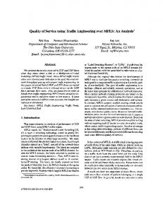
We verified that the function delay of load in the LSPs of the network shown in figure 13, is a convex one. To show such property we measured the delay suffered by packets under different load in the LSPs. We used Poisson’s traffic and we changed the mean of the interval between packets. For each load we measured the delay using the command MPLS PING, with different packets size: 1000 and 100 bytes, as shown in figure 14. Knowing the curves of delay in function of the load, we could assess the load balance that makes the network’s delay reach its minimum. In our topology, with a traffic of 1.5Mbps this proportion is 66 % of the traffic down the LSP2, as shown in figure 15.
4.5
Results of our implementation of MATE
We repeated several times the same kind of test and saved the values obtained. We analyzed the repetition of the convergence point with 20 tests, obtaining the distribution shown in figure 16. It is worth noting that the convergence point is similar to the one obtained by manual optimization, shown the later one in figure 15. The convergence occurred, in an average of 3 to 5 iterations, which means, in time, about 10 minutes for balancing two tunnels. The major portion of this time is consumed by the end-to-end measurements. These measurements are done for all the LSPs in the network, and constitute the bottleneck of all the monitoring process. As further evidence of the convergence, we made tests starting from a point of operation of strong imbalance in
delay=f(load) LSP 1
Histogram: results of the probes of MATE algorithm
160
45
Probe packets 1000bytes Probe packets 100bytes
LSP 1 LSP 2
40
140
35
120
30 % muestras
Delay(ms)
100
80
25 20
60 15 40
10
20
5
0
0 0
0.1
0.2
0.3
0.4
0.5
0.6
0.7
0.8
0
0.1
0.2
0.3
0.4
Load(Mbps)
0.5
0.6
0.7
0.8
0.9
1
load balance coefficient
(a) LSP1 Figure 16: Histogram. MATE algorithm’s convergence points. Curva delay=f(carga) LSP 2 220
Paquetes de prueba 1000bytes Paquetes de prueba 100bytes
200
Iterations of a MATE algorithm run
180 0.6
LSP 1 LSP 2
160 0.58 0.56 120 0.54
100 % balance de carga
Delay(ms)
140
80 60 40 20
0.52 0.5 0.48 0.46
0 0
0.2
0.4
0.6
0.8
1
1.2
0.44
1.4
Carga(Mbps) 0.42
(b) LSP2
0.4 1
1.5
2
2.5
3
n of iteration
(a) Load balance
Figure 14: Delay of load survey.
Delay evolution in a run of MATE algorithm 100 Delay Total=f(% LSP 2 load)
LSP 1 LSP 2 total
90
180
80 160
Delay (ms)
70
Delay(ms)
140
60
50
120
40 100 30 80
20 1
1.5
2
2.5
3
n of iteration 60 0.45
0.5
0.55
0.6
0.65
0.7
0.75
(b) Delays
0.8
%LSP2 Load(Mbps)
Figure 15: Optimum load balance coefficients search.
the distribution of the load, which means more traffic to the LSP with the smallest bandwidth. The result, as shown in Figure 17(a), was also the convergence of the algorithm. The optimum was different in this case because the input traffic was decreased, in order not to overfill the smallest LSP. Figure 17 shows how the algorithm actually makes the total delay to decrease. Even though it would have been very interesting to be able to compare our results with the ones shown in MATE [6], this would have been meaningless because in [6] they present results of a simulation, and our results are from a
Figure 17: Load balance coefficients and delays, during the performance of the algorithm.
real network. Then, it would not have been reasonable to compare, for instance, the execution time since in our implementation’s bottleneck is the live monitoring.
5.
CONCLUSION
In first place we conclude that we have successfully developed a complete Traffic Engineering tool, that works online and in MPLS networks. Such tool automatically performs all tasks involved in the process, including the topology discovery (virtual and physical), the recollection of per-
formance parameters, a congestion detection algorithm, another algorithm for congestion correction and the network reconfiguration. The study and research made before and during the development of this tool unveiled that having a none vendor dependant tool that performs the whole cycle of Traffic Engineering is not a resolved aspect nowadays. This made us conclude that our work is a promising step in the integration of the different tools that attack specific problems within the whole problem of Traffic Engineering in Telecommunication networks. Another important contribution of this project is to have planned, both in the design and in the implementation of each module, the expansion of the tool and the long-term evolution. The information collected in terms of performance parameters can be considered as an example of this approach. Such information is not limited to the one necessary for the Traffic Engineering algorithm that is implemented today, but a sufficient amount to represent the full performance of the network is collected. This meant, in turn, that during the final selection process of the algorithm the input parameters were not a limitation. Therefore, is considered highly likely that this limitation will not be present at the time of implementing another version of the Traffic Engineering module. The system was successfully implemented and tested in a live network. We worked in the validation of the complete tool and in the validation of processes’ dynamic, which allow us to conclude that the tool works according to what is expected: automatically detecting and correcting congestion. It is worth saying that the issue in question is very broad and, as it was mentioned in section validation, the results do not yet have information to determine whether implementation is scalable to networks with larger and more complicated topologies than our testbed. This leads an interesting work to perform in the future.
6. REFERENCES [1] Cooperation of Control and Management Plane for the Dynamic Provisioning of Connectivity Services on MPLS Networks. Eduardo Grampin Castro. A thesis submitted for the degree of Doctor per la Universitat Polit´ecnica de Catalunya. [2] Ingenier´ıa de Tr´ afico en L´ınea en Redes MPLS Aplicando la Teor´ıa de Grandes Desviaciones. Pablo Belzarena. Tesis de Maestr´ıa en Ingenier´ıa El´ectrica, Universidad de la Rep´ ublica, IIE, 2003. [3] Totem project: TOolbox for Traffic Engineering Methods. http://totem.info.ucl.ac.be. Last visit: 5/2009. [4] Metronet: Software para medici´ on de calidad de servicio en voz y video. Pablo Belzarena, V´ıctor Gonz´ alez Barbone, Federico Larroca, Pedro Casas. CITA 2006. [5] Data Networks. Dimitri P. Bertsekas y Gallager. Longman Higher Education, 1986. ISBN: 978-0131968257. [6] MATE: Multipath Adaptive Traffic Engineering. Anwar Elwalid, Cheng Jin, Steven Low y Indra Widjaja. Computer Networks, Vol. 40, No. 6, 2002, pp. 695-709. [7] Analysis and improvements to MATE algorithm. Miguel Griot, Gabriel Tucci, Pablo Belzarena y Santiago Remersaro. 23rd IEEE International Performance,
Computing and Communications Conference, Phoenix, Arizona, page 247–251 - 04/2004. [8] Aprovisionamiento de Conectividad en redes MPLS: Interfaz de Control. Alberto Castro y Mart´ın Germ´ an. Documentaci´ on de Proyecto de Grado, 2007. Universidad de la Rep´ ublica, Instituto de Computaci´ on. [9] Ingenier´ıa de Tr´ afico en Redes MPLS. Adri´ an Delfino, Sebasti´ an Rivero , Marcelo San Mart´ın. Proyecto Final de Carrera, 08/2005. Universidad de la Rep´ ublica, IIE. [10] Management Information Base for Network Management of TCP/IP-based internets: MIB-II. RFC 1213. Internet Engineering Task Force. [11] OSPF Version 2 Management Information Base. RFC 1850. Internet Engineering Task Force. [12] Multiprotocol Label Switching (MPLS) Traffic Engineering (TE) Management Information Base (MIB). RFC 3812. Internet Engineering Task Force. [13] Multiprotocol Label Switching (MPLS) Label Switching Router (LSR) Management Information Base (MIB). RFC 3813. Internet Engineering Task Force. [14] Multiprotocol Label Switching (MPLS) Forwarding Equivalence Class To Next Hop Label Forwarding Entry (FEC-To-NHLFE) Management Information Base (MIB). RFC 3814. Internet Engineering Task Force. [15] Ingenier´ıa de Tr´ afico en Redes MPLS. Adri´ an Delfino, Sebasti´ an Rivero , Marcelo San Mart´ın. Proyecto Final de Carrera, 08/2005. Universidad de la Rep´ ublica, IIE. [16] Ingenier´ıa de tr´ afico para tr´ afico multicast con MPLS. A. Lombide, I. Hern´ andez, J. Sanguinetti. Proyecto Final de Carrera, 12/2006. Universidad de la Rep´ ublica, IIE.