We do not propose that MOSAIC in its current form can serve as a âplug .... A composition-driven approach is to build smaller ele- ..... and b2 are generated to build the two networks: ..... Figure 6 shows the throughput of the download over time.
MOSAIC: Unified Declarative Platform for ∗ Dynamic Overlay Composition Yun Mao†‡
Boon Thau Loo† †
Zachary Ives†
University of Pennsylvania
ABSTRACT Overlay networks create new networking services across nodes that communicate using pre-existing networks. M OSAIC is a unified declarative platform for constructing new overlay networks from multiple existing overlays, each possessing a subset of the desired new network’s characteristics. M OSAIC overlays are specified using Mozlog, a new declarative language for expressing overlay properties independently from their particular implementation or underlying network. This paper focuses on the runtime aspects of M OSAIC: composition and deployment of control and/or data plane functions of different overlay networks, dynamic compositions of overlay networks to meet changing application needs and network conditions, and seamless support for legacy applications. M OSAIC is validated experimentally using compositions specified in Mozlog: we combine an indirection overlay that supports mobility (i3), a resilient overlay (RON), and scalable lookups (Chord), to provide new overlay networks with new functions. M OSAIC uses runtime composition to simultaneously deliver application-aware mobility, NAT traversal and reliability. We further demonstrate M O SAIC ’s dynamic composition capabilities by Chord switching its underlay from IP to RON at runtime. These benefits are obtained at a low performance cost, as demonstrated by measurements on both a local cluster and PlanetLab.
1.
INTRODUCTION
The Internet faces new challenges, ranging from unwanted or harmful traffic to increasingly complex and fragile interdomain routing. At the same time, new applications demand new capabilities such as mobility, content-based routing, and quality-of-service (QoS) routing. Overlay networks [23, 24] use the existing Internet to provide connectivity for new ser∗This material is based upon work supported in part by NSF CNS0721845, IIS-0477972 and IIS-0513778. Yun Mao was supported in part by Olga and Alberico Pompa Professorship of Engineering and Applied Science.
Permission to make digital or hard copies of all or part of this work for personal or classroom use is granted without fee provided that copies are not made or distributed for profit or commercial advantage and that copies bear this notice and the full citation on the first page. To copy otherwise, to republish, to post on servers or to redistribute to lists, requires prior specific permission and/or a fee. ACM CoNEXT 2008, December 10-12, 2008, Madrid, SPAIN Copyright 2008 ACM 978-1-60558-210-8/08/0012 ...$5.00.
‡
Jonathan M. Smith†
AT&T Labs - Research
vices, and permit deployable network evolution, while in some cases continuing to support legacy functionality [11]. Overlay networks have not, however, addressed the full set of challenges and evolutionary needs. We argue this is due to the lack of inter-operability among different overlays. Most overlays are targeted at vertical domains (e.g., mobility [34, 20], security [13], reliability [1]). However, many emerging applications and application domains have needs that are difficult to address using a single overlay. We illustrate an example usage scenario: E XAMPLE 1.1. Alice and Bob use private networks behind separate NATs, and wish to communicate regularly via VoIP or video conferencing, occasionally sharing data from internal web servers with trusted friends. As Alice and Bob travel regularly, and their IP addresses change, continued contact and communications should be seamless. In principle, Alice and Bob can use a combination of i3 [29] for NAT traversal, ROAM [34] for mobility, RON [1] for reliability, and if DoS attack prevention is important, a secure overlay such as SOS [13] can be added. This type of custom overlay offers benefits over a monolithic approach, e.g., Skype [28]: it can accommodate future application needs and changing network conditions. For example, RON may be excessive for a network with limited failures, and hence it may be desirable to remove it; whereas, in a partiallyconnected network, epidemic routing [30] would be desired. Further, Alice and Bob may require session-layer mobility support, hence requiring DHARMA [20] instead of ROAM. Combining overlays to achieve desired capabilities sounds straightforward, but it is challenging in practice. One must first identify combinations of overlays that can work together and provide the right set of capabilities. Then the mechanics of interconnecting the overlays must be tackled. Previous work [11] has shown that bridging between different overlays requires significant “glue code.” Layering one overlay over another is generally not even feasible, as each layer assumes it is running directly over IP. In this paper, we propose M OSAIC, a unified system that provides a declarative framework for developing, deploying, combining, and composing overlay networks — one capable of bridging between overlays, stacking them in layers, dynamically changing the layers or bridges, and allowing for rapid extensibility with new functionalities. It enables (1) rapid authoring and deployment of new overlay networks, (2) dynamic adaptivity to compose overlay networks to meet
bridging changing application needs and network conditions, and (3) seamless support for legacy overlay networks and applications within the infrastructure. This approach enables modular reuse of resources and functions. It also facilitates rapid experimentation and the deployment of new network features. This is a major step forward compared with existing hand-coded approaches [11] for manually bridging amongst different overlays. M OSAIC is based on declarative networking [17, 16], a declarative, database-inspired extensible infrastructure using query languages to specify behavior. Declarative programming allow programmers to say “what” they want, without worrying about the details of “how” to achieve it. This programming paradigm makes it easy to compose protocols, either vertically (layering) or horizontally (bridging), since composition is largely confined to the “what”, while composition of the “how” can be automated. It also provides better language and runtime support for dynamic adaption. In M OSAIC, overlay compositions are specified in a highlevel specification language, which is then further compiled into the Mozlog declarative networking language that defines the composed network protocols. Unlike previous declarative networking languages, Mozlog provides several novel language features essential for dynamic composition: dynamic location specifiers, combined with runtime types, enable flexible naming and addressing; composable virtual views support modularity and composability; data and control plane extensibility supports composition; declarative tunneling and proxying enable support for legacy applications. Our ultimate vision of automatically and dynamically composing overlays is well beyond the scope of a single paper. We do not propose that M OSAIC in its current form can serve as a “plug and play” replacement for existing network infrastructures. In particular, our work provides an execution framework, we leave as future work the challenges of automatic composition, including overlay network feature interactions. Our work is best viewed as a building block and step towards the grander agenda of intelligent, self-tuning networks [5]. Organization: Section 2 describes the options for overlay composition. Section 3 presents an architectural overview of the M OSAIC infrastructure. Section 4 summarizes the aspects of Mozlog important to M OSAIC. Section 5 illustrates the process of generating composition in Mozlog and use examples. In Section 6, we demonstrate how Mozlog specifications can be executed within a distributed query processor via modifications to the P2 declarative networking system. In Section 7, measurement results are presented for networks created on a local cluster and the PlanetLab testbed. We show that M OSAIC’s ability to support dynamic, flexible compositions can enable application-aware mobility, flexibility, and resilience with low overhead.
2.
OVERLAY COMPOSITION
Overlay network composition combines distinct parts or elements of existing overlay networks to create a new overlay network with new functionalities. M OSAIC enables overlay composition along both the data and control planes. Data plane composition. The data planes of two overlay networks can be composed horizontally by bridging between
IP tunnel
Receiver B
Network3 (QoS)
S d Sender Network1 ((confidentiality) y)
Network2 (reliability)
Receiver A
Figure 1: Overlay composition by bridging. the networks, or they can be composed vertically by layering one overlay over the other. In bridging (see Figure 1), each overlay network runs on top of the same substrate (e.g., the IP network) directly. However, for a variety of reasons (e.g., sending from a wireless to a wired network), it may be necessary to send a packet across multiple overlay networks to reach the receiver. This is usually done via a gateway node that belongs to both networks. If such gateways do not exist, two nodes from each network need to be connected via an IP tunnel to route packets. In Figure 1, a sending laptop using wireless may use an overlay that provides confidentiality to route traffic over the wireless links, then use an overlay with reliability guarantees to deliver important but not time-sensitive data to receiver A, while using a QoS overlay to deliver multimedia traffic to receiver B. RON Sender Receiver (1 hop from sender)
i3 router
i3
Sender Receiver (behind NAT)
Figure 2: Overlay composition by layering. In layering, logically a packet is routed within a single data plane of an existing overlay network. However, the data paths between the nodes inside the overlay may be constructed on top of other overlay networks, rather than IP. For example, RON only works for nodes that have publicly routable IP addresses. As shown in Figure 2, by composing RON on top of another overlay protocol that enables NAT traversal, such as i3, nodes behind NAT should be able to join the RON network. We note that the two data plane compositions listed above are not mutually exclusive; some data composition scenarios may combine both layering and bridging. Prior attempts to combine overlay networks [11] only support bridging but not layering. Layering adds a powerful new composition primitive that enhances individual overlay network nodes with multiple new services. Control plane composition. One overlay network’s control plane may be layered over either the data plane or the control plane of another overlay. For example, it is possible to build the control message channels of DHT protocols such as Chord over the data plane of RON. Typically, the failure detection components of DHTs assume that hosts unreach-
able via IP are dead. In fact, some hosts may be alive and functioning, but temporary network routing failures may create the illusion of node failure to part of the overlay nodes. If the network failures occur intermittently, churn rate is increased and may create unnecessary state inconsistency [9]. Using a resilient overlay such as RON can overcome some of the network failures and reduce churn. In a highly disconnected environment, one can further utilize epidemic [30] forwarding of control plane messages. Some overlay network protocols have complex, layered control planes. For example, both i3 and DOA [3] use DHTs for either forwarding or lookup. RON and OverQoS heavily depend on measurements of underlying network performance characteristics such as latency and bandwidth. When overlay networks are built from scratch over IP, it is conceivable that different logical overlays built on the same physical IP topology may duplicate the effort to maintain DHTs or perform network measurements. Nakao, et al. [22], observed that on PlanetLab, each node had 1GB outgoing ping traffic daily: many overlay networks running on the same node were probing the same set of hosts without coordination. Such duplicated probing traffic can be wasteful, and interactions between probe traffic may introduce measurement error. A composition-driven approach is to build smaller elements that provide well defined interfaces (e.g., OpenDHT [26] for DHT lookup and iPlane [18] for measurement) so that they can be easily composed with upper layer overlay network control planes to share rather than compete for resources.
3.
MOSAIC OVERVIEW
In this section, we provide an overview of M OSAIC, and describe how it provides a framework for composing and re-composing overlay networks. Note that we do not currently tackle the issue of determining the compositions, but rather provide the overlay composition specification and implementation framework. M OSAIC is designed to be deployed as a composition service on a shared overlay infrastructure where all nodes run the M OSAIC engine. On this infrastructure, several overlay networks may co-exist, and are not necessarily deployed on all nodes. Individual overlay protocols are specified using the Mozlog declarative networking language, then compiled and executed in M OSAIC. Composed overlay networks are instantiated by leveraging existing deployed overlays, either by layering (above or below) or bridging with them. In addition, private networks outside of the infrastructure are bridged via public gateways with overlays deployed on this infrastructure. Since the composition glue code is written in Mozlog, it is most natural to implement each individual overlay as a declarative network in Mozlog. However, M OSAIC can also support legacy overlays with the use of an adapter (see Section 6.2). M OSAIC engine. Figure 3 illustrates the M OSAIC engine from the perspective of a single node. M OSAIC is positioned at the network layer in the network stack, replacing IP. It exposes a simple interface to the transport layer by providing two primitives: send(DestAddress, Packet) and recv(Packet). In IP, a packet consists of an IP header with fixed format and a data payload not interpreted by IP. In M OSAIC, Packet is represented abstractly as a structured
data element, which might be a set of scalar values or even nested tuples. The encoding of this packet is up to the specific overlay protocol, and declarative mappings or transformations can convert between the packet formats of different overlays (see Section 4). DestAddress is a specially typed tuple, with the first attribute being the identifier of the overlay network to which the packet belongs. This identifier is used to demultiplex the send requests to different overlays or IP at the network layer. A send request will trigger a recv event at the node or nodes who own the DestAddress if the network successfully routes the packet. Directory service. For each overlay running on the infrastructure, there is a directory service that maintains the following information: (1) A unique identifier for the overlay; (2) The list of physical nodes that is currently executing the overlay; (3) The list of users who can utilize the overlay, and their privileges (e.g., whether they can bridge with this overlay). These privileges are set by an overlay’s owner; and (4) Additional meta-data that describes the overlay, such as its attributes, node constraints, etc. As part of the process of creating a composed overlay, the user may issue queries to the directory, searching for existing overlays that meet their criteria for composition. The directory service may be provided either by a centralized server or in a distributed fashion [7, 2] for scalability. The design choice of the directory service is orthogonal to the M OSAIC architecture. In this paper, we focus on the use of a centralized server. We note that a centralized service is sufficient for maintaining the metadata information for thousands of infrastructure nodes, as demonstrated by PlanetLab central [24]. Composition process. To create a composed overlay network, a M OSAIC user (e.g. a network administrator) first uses the directory service to locate overlay networks that meet their criteria for composition, and retrieves relative metadata information . Second, the administrator creates a composition specification, which is a high-level graph-based description of the desired component overlay networks and their interactions. Then, the specification is compiled into the Mozlog language used by M OSAIC’s compiler, described in Section 5. As part of this process, new code is created that “glues” the compositions together. Finally the generated Mozlog code is deployed to the physical nodes to start the new network, and the directory information is updated regarding the newly composed network. The declarative approach provides major benefits. First, there are the traditional benefits of declarative networks in terms of compactness and safety. Second, protocols are specified at a higher level, making them more modular. Finally, high-level composition specifications have potential for correctness checks and for making inferences about the compositions’ attributes — and especially for reasoning about feature interactions among different overlays. For example, an insecure overlay when bridged with a secure overlay will result in an end-to-end insecure overlay. A scalable lookup overlay will increase its robustness when executing over a resilient overlay, at the expense of its performance.
3.1
Composition Specifications
Figure 4 shows a graphical representation of a composi-
Transport Layer Overlay 1 Specification
send
Overlay 2 Specification
recv
Overlay 1
Compiler
dataflow
i3
Overlay 2
IP
Alice’s internal network
Compiler
dataflow
tables
tables
Alice’s gateway
RON
Bob’s gateway
Bob’s internal network
N t Network kL Layer iin MOSAIC
Figure 3: An overview of the MOSAIC engine for network layer overlays. tion specification, based on the example scenario introduced in Section 1. We chose XML as the internal representation to describe the graph. Due to space constraints, the corresponding XML representation is presented in the technical report [21]. Each module (node) represents a component overlay network (e.g., i3 and RON) deployed on the infrastructure, or a private network. The links represent connectors, where vertical and horizontal links denote layering and bridging, respectively. Here, the i3 overlay is layered over RON; Alice and Bob’s private networks are bridged to RON. In addition to a unique overlay identifier, each module configuration consists of the following: • Physical node constraints: When the overlay is first deployed, the user who created the overlay can constrain the set of nodes on which the overlay may execute. This can be in the form of a prefix to indicate that nodes must be deployed on particular subnets, or enforce the inclusion of particular nodes (e.g. Alice’s and Bob’s gateways) must be on both the i3 and RON networks. • Attributes: Each overlay network has properties that characterize its capabilities, including mobility, secure routing, NAT traversal, resilient routing, anonymity, private networks, etc. These properties can be queried by users to identify overlays that meet their requirements. • Code: If a module is loaded for the first time, code can be included in the configuration. This can either be legacy code, or Mozlog specifications for declarative networks. • Default gateway: Each module can specify a default gateway for bridging. In the absence of a specified gateway, the a common physical node sitting on both networks is selected to serve as the gateway. • Access control: M OSAIC supports restrictions on which users can utilize an overlay, and their privileges (e.g., layering above or below, and bridging, etc.). The connectors between modules have properties associated with them. Bridging (horizontal lines) must specify whether there are default gateways to be used, and whether tunneling is permitted. If two modules are specified to be bridged via a default gateway node, both overlays must run on the specified gateway. Layering (vertical lines) also has constraints on whether the overlay has to be layered on all or subset of the nodes. In this example, to get the full benefits of RON, all i3 nodes should utilize RON as their underlay. However, this is not strictly required: i3 nodes that do not run RON will default to using IP. For both bridging and layering, one can further specify whether some connections replace existing ones.
Figure 4: Graph of i3 layered over RON, and private networks of Alice and Bob bridged with RON.
3.2
Composition Compilation
Once the composition is specified, a composition compiler is used to generate the Mozlog code that “glues” together different overlay networks based on the specifications. The compiler is either a client-side software, or deployed as a service in conjunction with the directory service. The compilation process can be performed in two different ways. First, a composition can create overlays, either from scratch where each module contains the code implementing each overlay, or incrementally where the new overlay is built on existing ones, e.g., by adding new overlays over existing ones, or bridging overlays via identified gateways. Creating overlays incrementally requires the composition specifications to refer to existing overlays by their unique identifiers. Second, a composition can also modify overlays, which involves replacing existing modules with new ones, and this requires connectors to indicate that they are replacing existing composition links. Given the above mechanisms, we outline how layering and bridging can be achieved by compiling modules and connectors, and provide a detailed process description and examples in Section 5. The first step is to perform basic checks to ensure all the links are legal, based on the attribute constraints and physical node constraints. E.g., one cannot layer one overlay over another if they are configured for completely disjoint sets of nodes. Two overlays cannot be bridged if their bridge connector does not permit tunneling and the two overlays do not share any common node. Once validated, Mozlog rules for composition and all required overlay code are uploaded to relevant nodes for execution.
3.2.1
Layering
Layering of a control or data plane over another overlay’s data plane is achieved by ensuring that every protocol uses logical addresses — rather than being bound to physical addresses. At runtime M OSAIC will bind (or rebind) the upper layer’s logical address to the underlay address. These bindings are stored in a separate table that can be updated to facilitate dynamic changes to layering. M OSAIC allows the control plane of one overlay network to layer over another overlay’s control plane, accessing its internal state. Here, each overlay exports the state of its composable components, in the form of database logical views (query results presented as a named table). An example of such state is a distributed hash table’s contents, which can be modeled as a relation with tuples associating keys and values. Importantly, accessing a neighboring protocol’s state
can be done within the overlays’ specification language — there is no “impedance mismatch” between languages, and interoperability issues are minimal.
3.2.2
Bridging
Depending on requirements, bridging can be done either pre-configured or on-demand in M OSAIC. Pre-configured method. When the composition specification involves bridging multiple overlays, forwarding state is created on designated gateways based on the bridge connectors indicated in the composition specifications. When a sender sends a packet whose destination contains an address of an overlay in which the sender does not participate, M O SAIC routes the packet to the gateway, which then continues to forward the packet along the bridged overlay. In addition to a static gateway, the sender can also use a pre-configured anycast service [12, 8] to select and route packets to one of the overlay nodes, preferably close in terms of network distance to the sender. On-demand method. The sender utilizes source routing to explicitly describe the data path to the destination via designated gateways among different overlays found in the specification. Alternatively, the gateway holds address translation state that uniquely identifies the flow between the sender and the receivers, it performs indirection. The on-demand mechanism enables user-driven dynamic bridging. We will describe several examples of such compositions in Section 5.4 using the Mozlog language.
3.3
Dynamic compositions
M OSAIC exploits Mozlog’s declarative model to facilitate dynamic overlay composition: since network definitions in M OSAIC separate specification from implementation, the system can (assuming the right constraints are met) freely replace either the IP or an existing overlay underneath one overlay network with a second overlay network — i.e., it can layer networks. For example, the protocol used in RON is a modified link-state protocol, which is general enough to operate on any connected graph. The original RON implementation assumes IPv4 as a substrate, and hence it is hard-coded to use publicly routable IP addresses. In M O SAIC , protocols are written with a network-agnostic addressing scheme, so a RON overlay can instead use addresses from one or more lower-level overlay networks, provided they are reachable from one another. This allows M OSAIC to dynamically switch an existing overlay’s underlay based on the network conditions, e.g., an executing overlay that utilizes IP can dynamically layer itself over RON when routing losses are high, or further switch to an epidemic forwarding strategy when the network is disconnected. Dynamic overlay switching in M OSAIC is achieved by changing the binding between an upper overlay’s logical addresses and the underlying network and its (lower-level) addresses. This technique is overlay-agnostic. However, we must be careful to preserve application and overlay semantics. In particular, if dynamically switching maintains the same endpoints on route requests (as RON, above, does), then the switch is permissible. Likewise, if the lower overlay state is not visible to the layers above, and all endpoints provide the same functionality (e.g., in a content distribution network),
then the switch is also permissible. In other cases, we would need to re-architect the overlays and possibly the application to redistribute state over the new underlay, and to be tolerant of transient states.
4.
THE MOZLOG LANGUAGE
Having described M OSAIC’s basic composition framework, we next present the Mozlog declarative networking language that is generated from the composition specifications. As with previous declarative networking languages [17, 16], Mozlog is based on the Datalog [25] query language, and extends Datalog in novel ways to support composition. As background, each Datalog rule has the form p :- q1, q2, ..., qn., which can be read informally as “q1 and q2 and ... and qn implies p”. Here, p is the head of the rule, and q1, q2,...,qn is a list of literals that constitutes the body of the rule. Literals are either predicates with attributes (which are bound to variables or constants), or boolean expressions that involve function symbols (including arithmetic) applied to attributes. (Predicates in Datalog are typically relations, although in some cases they may represent functions.) Datalog rules can refer to one another in a cyclic fashion to express recursion. The order in which the rules are presented in a program is semantically immaterial; likewise, the order predicates appear in a rule is not semantically meaningful. Commas are interpreted as logical conjunctions (AND). The names of predicates, function symbols, and constants begin with a lowercase letter, while variable names begin with an uppercase letter. Mozlog is a distributed variant of traditional Datalog, primarily designed for expressing distributed recursive computations common in network protocols. We illustrate Mozlog using a simple example of two rules that compute all pairs of reachable nodes: r1 reachable(@S,D):-link(@S,D). r2 reachable(@S,D):-link(@S,Z), reachable(@Z,D).
The rules r1 and r2 specify a distributed transitive closure computation, where rule r1 computes all pairs of nodes reachable within a single hop from all input links, and rule r2 expresses that “if there is a link from S to Z, and Z can reach D, then S can reach D.” By modifying this simple example, we can construct more complex routing protocols, such as the distance vector and path vector routing protocols. Mozlog supports a location specifier in each predicate, expressed with @ symbol followed by an attribute. This attribute is used to denote the source location of each corresponding tuple. For example, all reachable and link tuples are stored based on the @S address field. The output of interest is the set of all reachable(@S,D) tuples stored at node S, representing reachable pairs of nodes from S to D. In this section, we highlight the Mozlog language itself; we provide detailed compilation process from composition specification to Mozlog and use cases in Section 5, and discuss implementation details in Section 6. We focus first on key language features necessary to support overlay composition we then briefly summarize other interesting language features in Section 4.3.
4.1
Addressing
Mozlog has two distinctive features for addressing nodes in the network. First, a location specifier is decoupled from
the data tuple so that tuples can be accessed from multiple logical overlay networks that the host belongs to. Second, because multiple overlays are selected and composed dynamically, location specifiers are not bound to IP addresses anymore. Each location specifier is associated with a runtime type which is bound to an overlay.
4.1.1
Decoupling Location from Data
Mozlog predicates have the following syntax: predicate[@Spec](Attrib1,
Attrib2, ..)
In the absence of any location specifier, predicate is assumed to refer to local data. In this case, the rule body is executed as a Cartesian product across all input tables. For example, in the following rule, a1 alarm@R(L, N) :- periodic(10), cpuLoad(L), nodeName(N), monitorServer(R), L>20.
is a built-in local event that will be triggered every 10 seconds. The predicates cpuLoad, nodeName, and monitorServer are local tables. The rule specifies that for every 10 seconds, if the CPU load is above the threshold 20, an alarm event containing the current load L and host name N will be sent to the monitoring server R. Decoupling data from its location enhances interoperability and reusability, as well as dynamic re-binding of addresses. Multiple overlays can interoperate (i.e., exchange state) by sending network-independent data tuples in a common data representation. Moreover, since these rules are rewritten in a location-independent fashion, they can be reused on different network types (e.g., i3, RON, or IP). Finally, since it does not bind addresses to data, the language is friendly to mobility, where host movement (and hence a resulting change in its IP address) does not invalidate its local tables.
periodic
4.1.2
Runtime Types for Location Specifiers
Another Mozlog feature involves adding support for runtime types to location specifiers. This feature is necessary for dynamically composing multiple overlays at runtime. Location specifiers are denoted by an [oID::]nID element, where oID is an optional overlay identifier, and nID is a mandatory overlay node identifier. For example, consider i3 and RON overlays with identifiers i3 oid and ron oid respectively. i3 oid::0x123456789I denotes an i3 node with identifier 0x123456789I, and ron oid::12.34.56.78 denotes a RON node with IP address 12.34.56.78. In the absence of any overlay identifier, IP is assumed. At runtime, M OSAIC examines the location specifier of each tuple and routes it along the appropriate network. To illustrate the flexibility of our addressing scheme, consider the CPU load monitoring example from Section 4.1. Rule a1 can be rewritten as a2, in which the monitoring server R refers to an i3 key generated as a hash of its name N instead of an IP address: a2 alarm@R(L, N) :- periodic(10), cpuLoad(L), nodeName(N), serverName(SN), L>20, Key := f_sha1(SN), R:=i3_oid::Key.
4.2
Data and Control Plane Integration
Overlay composition requires the integration of the data and control planes of multiple overlays. To achieve this,
Mozlog enables declarative specification of the data plane behavior. Given an overlay oid, oid.send and oid.recv event predicates specify the data forwarding algorithm. We will describe how these send and recv events are generated within the dataflow execution framework later in Section 6. Focusing on the language feature now, we illustrate this feature via an example based on the data plane of an RON overlay ron oid. snd ron_oid.send@Next(Dest,Pkt) :ron_oid.send(Dest, Pkt), ron_oid.RT(Dest, Next), localAddr(Local), Local!=Dest. rcv ron_oid.recv(Pkt) :- ron_oid.send(Dest, Pkt), localAddr(Local), Local==Dest.
The table ron oid.RT denotes the RON routing table. Rule expresses that for all non-local Dest addresses, the data packet (Pkt) is sent along the next hop (Next) which is determined via a join with RON’s routing table (ron oid.RT) using Dest as the join key. These packets are then received via the rule rcv at node (Dest), which generates a oid.recv(Pkt) event at Dest. In Mozlog, the send and recv predicates are usually not directly used by other rules, but rather automatically invoked by the M OSAIC runtime engine when the location specifier type of a tuple matches the overlay. As a result, one can bridge the data planes of different overlays together, or layer the control plane of one overlay network over the data plane of another. We provide more details in Section 5. snd
4.3
Other Language Features
Finally, we briefly present several language features that, although not directly used in composition, are essential for rapid development, code reuse, and legacy application support. Mozlog supports Composable Virtual Views (CViews), that define rule groups that, when executed together, perform a specific functionality, such as DHT lookup and network measurement. CViews promote code reuse and enable functional composition between different overlays. In addition, CViews abstract details of asynchronous event-driven programming. This enhances readability and makes the code even more concise: the use of CViews reduced the number of lines in Chord by 8 rules (from 43 to 35). A detailed discussion of CView is outside the scope of this paper. Mozlog also supports a built-in tun predicate specifically reserved for representing tunneled traffic via the tun virtual network device. This allows legacy applications listening on the tun device to seamlessly tunnel traffic through M OSAIC overlay compositions. The tun predicate has the following schema: tun(IPPkt [,SrcIP, DestIP, Protocol, TTL]). IPPkt represents the IP packet that is being tunneled. In addition, the IP header fields SrcIP, DestIP, Protocol and TTL are optionally extracted and included as additional attributes when they are required in Mozlog rules. The following rules demonstrate the tun predicate for tunneling via a point-topoint and i3 overlay respectively: p2p_tun tun@Peer(Pkt) :- tun(Pkt), Peer:="12.34.56.78:1086". i3_tun tun@Peer(Pkt) :- tun(Pkt, Src, Dest), Key:=f_sha1(Dest), Peer:=i3_oid::Key.
Rule p2p tun sets up a point-to-point UDP tunnel between the local node and the remote node listening at the UDP ad-
dress 12.32.56.78:1086. This allows legacy applications at two end-points to communicate via a UDP tunnel implemented by M OSAIC. Similarly, in rule i3 tun, a tunnel is set up via the i3 overlay. All packets generated by the legacy application is sent via this rule to a remote legacy application running at the i3 node with logical address Key generated using the SHA-1 hash of the destination tunneling address. See Section 6.2 for implementation details.
5.
COMPILING COMPOSITIONS
This section describes how the M OSAIC compiler automatically translates specifications into Mozlog rules. We first define the following reserved tables at each node, which are used in the composition process later: • netAddress(OID,Addr) tracks all current addresses Addr of the overlays OID in which the node participates. If a node has a publicly reachable IP address, a default entry is added as (0,current ip), where 0 is a reserved ID for the Internet. OID can also refer to a bridged network, in which case Addr can refer to a source routing address (See Section 5.3). Other overlay specific addresses are maintained by the corresponding overlay modules. • underlay(OID,Addr) is used in layering. It stores the mapping from an overlay’s OID to its current underlay’s runtime address Addr for each deployed overlay. By updating this table, one can switch the underlay being used. • forward(OID,Addr) is used in bridging. It specifies that all packets designated for overlay OID are to be sent to the designated gateway with address Addr.
5.1
Compilation Steps
To create an overlay network composition from scratch, the M OSAIC compiler takes as input a composition specification as presented in Section 3, and then automatically performs the following steps to generate Mozlog rules that bridge and layer the appropriate overlay modules: • Check that the specification includes gateway nodes that are shared by both networks to be bridged, or anycast services are provided to locate overlay entry nodes. • Compute the node membership sets to which each overlay module is to be deployed. This includes all nodes satisfying the physical node constraints discussed in Section 3.1, which are also members of any underlay network. • For each overlay layered over another module, add mappings binding each node’s logical address in the current overlay to a lower-level underlay address in the underlay table. (Section 5.2.) • For each overlay module with a bridge, based on the specification, add pre-configured forwarding state entries in the forward table or on-demand source routing rules to all member nodes, specifying either the static address of each bridged network’s gateway node or the anycast address with each bridged network’s ID. (Section 5.3.) • For all newly created overlays, including both bridged and layered ones, add a rule to store the overlay’s address in the netAddress table. See Section 5.2-5.3 for details. After the compilation, the rules are shipped to the corresponding physical nodes for deployment.
To modify an existing network composition, most of the procedure remains the same except that the node membership sets of existing overlays are obtained by querying the directory service, and modified Mozlog rules are uploaded to the physical nodes to implement the new composition.
5.2
Layering
Layering of a control or data plane over another overlay’s data plane is achieved through the use of the underlay table describing bindings from each overlay node to its current runtime underlay address. Abstracting the bindings into a table provides a simple mechanism for switching overlays: M OSAIC can simply update the underlay table — changing both the underlay protocol and node address as appropriate. Given a composition specification with layering connectors, Mozlog rules are generated to implement the layering in an overlay-specific fashion. We illustrate using an example where there are two RON overlays, layered over IP and i3. Based on the specifications, at every node, there are two instances of RON executing ( ron oid1 and ron oid2), and one instance of i3 (i3 oid). The following Mozlog rules b1 and b2 are generated to build the two networks: b1 underlay(ron_oid1,U):-netAddress(0,U). b2 underlay(ron_oid2,U):-netAddress(i3_oid,U). Since ron oid1 utilizes IP for routing, rule b1 takes as input netAddress(0,U), based on the executing node’s default IP address. On the other hand, ron oid2 routes over i3,
hence its underlay tuple stores the address of the underlying i3 oid node retrieved from the local netAddress table. Note that the layering association is not static. A deployed, running overlay network can switch the underlying network from one to another by updating its underlay table entries at runtime. This enables dynamic overlay composition. We will discuss an example of dynamic switching in Section 5.4. Next, the rule to update the netAddress table is generated for the newly created overlay. For example, consider the i3 and RON overlays with identifiers i3 oid and ron oid respectively. In i3, its overlay address is the SHA-1 hash of the node’s public key K (as shown in rule d1). d1 netAddress(i3_oid, A) :publicKey(K), A:=i3_oid::f_sha1(K).
On the other hand, in RON, since its routable address is tightly coupled with its underlay, its address is its own underlay address (typically the IP address that RON uses) annotated with the overlay id as shown rule d2: d2 netAddress(ron_oid, A):underlay(ron_oid,U), A:=ron_oid::U.
Finally, data plane forwarding rules may also need to be slightly changed. We update the RON forwarding rules snd and rcv from Section 4.2 in the context of layering: snd ron_oid.send@Next(Dest,Packet) :ron_oid.send(Dest, Packet), ron_oid.RT(Dest, Next), underlay(ron_oid, Local), Local!=Dest. rcv ron_oid.recv(Packet) :ron_oid.send(Dest, Packet), underlay(ron_oid, Local), Local==Dest.
The local address stored in localAddr is replaced by where Local is the current underlay address of the overlay ron oid. Note that while the above rules achieve the same functionality as the previous two rules in Section 4.2, they are more flexible in allowing packets to route over underlays that can be switched at runtime. underlay(ron oid,Local),
5.3
Bridging
Language-level support for bridging is accomplished in either of two ways. In the pre-configured method, the default gateway Addr for overlay oid in the specifications is stored in the table. M OSAIC routes a packet designated to overlay oid towards Addr, and the process repeats recursively until the gateway is reached; at that point, the forward table will no longer have an entry for the overlay oid, and instead it will route the packet according to its own policy. If Addr is set to a static IP address, this is equivalent to setting up an IP tunnel to the gateway. If Addr is an anycast address, e.g. oasis oid::oid, the forwarding plane will invoke the Oasis anycast service to locate the closest oid overlay node from the current node, and use it to enter the overlay. Alternatively, in the on-demand method, a source route can be set up for each packet. Mozlog supports an address type of the form sr::[gateway, dest], which explicitly describes the data path in terms of logical addresses. All nodes will automatically handle the forwarding of such messages to the next recipient in the path. Dynamic location specifiers enable bridging of different overlays easily. For example, node A is hosted in an internal network with an internal IP address ip a. Thus its address is recorded in the netAddress table as (a net id, ip a). Here a net id is a unique identifier of A’s internal network. Recognizing that ip a is an internal IP, the composition server will create a routing path via the gateway node that sits on both the Internet and the internal net to bridge the two networks. The bridged network address is encoded in the source routing format as sr::[ip gw, ip a] and stored in the netAddress table. If we layer RON over the source routing address, node A can immediately join a RON network without a public IP address.
5.4
Composition Examples
We now demonstrate M OSAIC’s ability to support flexible overlay compositions including bridging, layering and hybrid compositions. We present two examples, one that revisits the mobile VoIP example introduced in Section 1, and a second example that illustrates dynamic composition. VoIP between Alice and Bob: Consider the example mentioned in Section 1. An overlay composition can solve the problem. Suppose there is a publicly available i3 overlay network, and Alice uses her gateway node at home to form a private RON network with Bob and her other friends. Alice and Bob agree on the composition specification shown in Figure 4. Based on the overlay specification, M OSAIC generates the Mozlog rules to compose overlays together. Because Alice’s situation mirrors Bob’s, we use Alice’s rules and network state to explain the composition process. First, at Alice’s gateway, we configure the RON overlay network over IP as: c1 underlay(ron_oid,A):-netAddress(0,A).
We then use bridging to create publicly reachable addresses and br2 as shown in Table 1. br1 bridges the internal network AliceNet with the public IP network, and br2 bridges AliceNet with the RON network. Finally, we layer i3 over the bridged networks we create. Because Alice wants to have reliability for VoIP, we choose the bridging overlay with BR2 as i3’s underlay. The composition rules deployed at the Alice node is as follows:
br1
overlay id alice net br1 br2 i3 oid
address alice internal ip sr::[alice gateway ip, alice internal ip] sr::[ron::alice gateway ip, alice internal ip] i3 oid::alice id
Table 1: netAddress table at Alice overlay id 0 alice net ron oid
address alice gateway ip alice gw internal ip ron oid::alice gateway ip
Table 2: netAddress table at Alice’s gateway c2 underlay(i3_oid,A):-netAddress(br2,A).
When Bob initiates a VoIP call to Alice, he first uses Alice’s i3 ID to look up her public trigger, and sends traffic to Alice via i3’s indirection path. After they have located each other, they switch to the i3 shortcut data path as the underlay network specifies, which is layered on top of RON and can traverse internal networks (e.g., those behind NATs) using source routing along the gateways. Dynamic Composition of Chord over IP and RON: To illustrate dynamic composition, we use the Chord DHT to show the benefit of dynamically switching the underlying data path from IP to RON. In Chord, temporary network failures may create non-transitive connectivity between the nodes, possibly creating problems such as invisible nodes, routing loops and broken return paths [9]. Instead of altering the DHT protocol, an alternative is to layer Chord over a resilient routing protocol such as RON that eliminates nontransitivity. Layering Chord over RON can be viewed as trading scalability for performance. The following rules define two type of layering: Chord over IP and Chord over RON: s1 underlay(chord_oid,A):- netAddress(OID,A), switchUnderlay(OID). s2 underlay(ron_oid,A):- netAddress(0,A).
In s1-s2, we added a switchUnderlay(OID) predicate to switch Chord’s underlay to that indicated by the OID variable. This switchUnderlay can itself be triggered by an event sent from the administrator based on changes to the overlay specifications. Rule s1 indicates that Chord uses IP as the underlying address when OID is 0, and RON when OID is ron oid. Rule s2 defaults RON to use IP at all times. To switch between the two layering schemes, one only needs to generate switchUnderlay accordingly. Dynamic switching is useful because the trade-off between scalability and performance is at the discretion of the Chord administrators, who can make decisions based on network conditions, requirements, etc. Suppose a new overlay providing both resiliency and scalability (e.g. SOSR [10]) is available later, one can switch Chord’s underlay from RON to the new one to further improve scalability. Unlike restarting Chord from scratch, dynamic switching preserves existing state in the network such as key/value pairs without disrupting the DHT lookup service. Once the Chord underlay network address is changed on a node, the stabilization process will propagate it to the node’s successors, predecessor and other nodes that have it in its finger table. We present our experimental evaluation of this example in Section 7.3.
6.
IMPLEMENTATION
The M OSAIC platform builds on the P2 [16] declarative networking system and adds significant new functionality. The P2 planner and dataflow engine have been revised to generate execution plans that accommodate new language features of Mozlog: specifically, those related to runtime support for dynamic location specifier, data plane forwarding, and interactions with legacy applications. M OSAIC takes a Mozlog program, compiles it into distributed P2 dataflows [16], and deploys it to all nodes that participate in the overlay. A single node may host multiple overlay networks at the same time. P2 dataflows resemble the execution model of the Click modular router [14], which consists of elements that are connected together to implement a variety of network and flow control components. In addition, P2 elements include database operators (such as joins, aggregation, selections, and projections) that are directly generated from queries. Each local dataflow participates in a global, distributed dataflow across the network, with messages flowing among elements at different nodes, resulting in updates to local tables. The local tables store the state of intermediate and computed query results, including structures such as routing tables, the state of various network protocols, and data related to their resulting compositions. The distributed dataflows implement the operations of various network protocols. The flow of messages entering and leaving the dataflow constitute the network packets generated during query execution.
6.1
Dataflow Execution
sulation of tuples from overlay traffic. At the top of the figure, the Mux multiplexes incoming tuples received locally or from the network. These tuples are processed by the OverlayRecvUnwrap element that will extract the overlay payload for all tuples of the form overlay. recv(Packet), where Packet is the payload with type tuple. Since the payload may be encapsulated by multiple headers (for layered overlays), this element needs to “unwrap” until the payload is retrieved. The Packet payload is then used as input to the dataflow via the ReceiveDemux element, and used as input to various rule strands for execution. Executing the rule strands results in the generation of output tuples that are sent to a LocSpecDemux element. This element checks the runtime type of the location specifier, and then demultiplexes as follows: • Tuples tuplename(F1, F2, ..., Fn) are local tuples and sent to the Mux. • Tuples tuplename@IPAddr(F1, F2, ..., Fn) are treated as regular IP-based tuples and sent to the network directly. • Tuples tuplename@oid::ovaddr(F1, F2, ..., Fn) are designated for overlay network oid with address ovaddr. A new event tuple oid.send(ovaddr, tuplename(F1, F2, ..., Fn)) which denotes the send primitive of the overlay network oid is generated (see Section 4.2). This new tuple is reinserted back to the same dataflow to be forwarded based on the overlay specification.
6.2
Legacy Support
We use the tun device to provide overlay tunnels between legacy applications at the network layer. The tun special predicates for legacy support are treated differently from orNetwork In dinary tuples in the dataflow. Each special predicate has a Overlay TimedPullPush rule strand in the dataflow, between the ReceiveDemux eleMux Queue Recv 0 Unwrap ment and the RoundRobin element (see Figure 5). Two elements Tun::Tx and Tun::Rx are inserted in the tun rule strand right after ReceiveDemux. Tun::Rx reads IP packets from the tun device, generates the tun tuple, and sends to Receive Round Demux Robin the next element in the rule strand; Tun::Tx receives a tun tuple, formats it as an IP packet and writes to the tun device. For each end host, it takes a private IP address from 1.0.0.0/8 Overlay overlay to avoid conflict from other public IP networks. After a Send Wrap LocSpec TimedPullPush legacy application sends a packet to an address in the tun netlocal Demux 0 work, the kernel redirects it to M OSAIC, where the Tun::Rx Network Out Queue IP element generates a tun tuple. Currently there is an address translation rule to use a special mapping table to translate Figure 5: System dataflow & dynamic location specifiers. the private IP address to the overlay address. This can be extended to use any name resolution service in the future by Figure 5 shows a typical execution plan generated by comcombining DNS request hijacking [11]. After address transpiling Mozlog rules. Similar to P2 dataflows, there are sevlation, the packet tunneling rules such as rule i3 tun we deeral network processing elements (Network In and Network scribed in Section 4.3 deliver the IP packet to the destination Out) that connect to individual rule strands (inside the gray via the corresponding overlays. After the tun tuple is delivbox) that correspond to compiled database operators. Here, ered to the remote node, it is redirected to the tun device we focus on our modifications, and the interested reader is by the element Tun::Tx, and finally the tunneled packet is referred to [16] for details on the dataflow framework. received by the legacy application. To implement dynamic location specifiers and overlay forTo support a legacy overlay that is not implemented in warding on the data plane, we modify the planner to autoM OSAIC, we build an adapter for the overlay to interact with matically generate three additional M OSAIC elements shown M OSAIC via the send and recv primitives. The adapter rediin bold in the dataflow: OverlayRecvUnwrap, OverlaySendWrap, rects legacy.send tuple from the dataflow to the overlay, and LocSpecDemux. The elements OverlayRecvUnwrap and and inject legacy.recv tuple upon overlay’s packet recepOverlaySendWrap are used for de-encapsulation and encaption. Because the legacy overlays are built on IP, they can
test latency(ms) throughput (KByte/s) DirectIP 0.10 97994 OpenVPN 0.30 13951 MozTun 0.50 8353 RON 0.71 5796 i3 1.31 3299 Table 3: Overhead comparison in LAN only be bridged with other overlays or used as substrates underneath other networks, but cannot be layered on top of another overlay for either the control or the data plane.
7.
EVALUATION
In this section, we present the evaluation of M OSAIC on a local cluster and on PlanetLab. First, we validate that Mozlog specifications for declarative networks, compositions, tunneling and packet forwarding are comparable in performance to native implementations. Second, we use our implementation to demonstrate feasibility and functionality, using actual legacy applications that run unmodified on various composed overlays using M OSAIC. Third, we evaluate the dynamic composition capabilities of M OSAIC. In all our experiments, we make use of a declarative Chord implementation which consists of 35 rules. Our i3 implementation uses Chord and adds 16 further rules. We also implement the RON overlay in 11 rules. Both i3 and RON can be used by legacy applications via the tun device, as described in Section 4.3.
7.1
LAN Experiments
To study the overhead of M OSAIC, we measured the latency and TCP throughput between two overlay clients within the same LAN. The experiment setup was on a local cluster with eight Pentium IV 2.8GHz PCs with 2GB RAM running Fedora Core 6 with kernel version 2.6.20, which are interconnected by high-speed Gigabit Ethernet. While the local LAN setup and workload is not typical of M OSAIC’s usage, it allows us to eliminate wide-area dynamic artifacts that may affect the measurements. We measured the latency using ping and TCP throughput using iperf. In the experiments, we use the tun device to provide legacy application support for network layer overlays. MTU was reduced to 1250 bytes to avoid fragmentation when headers were added. The measurement results are shown in Table 3 for the following test configurations: DirectIP: Two nodes communicate via direct IP, where iperf can fully utilize the bandwidth of the Gigabit network. This serves as an indication of the best latency and throughput achievable in our LAN. OpenVPN: OpenVPN [32] 2.0.9 is a widely used tunneling software. We set up a point-to-point tunnel via UDP between two cluster nodes and disabled encryption and compression. The performance results provide a baseline for the overhead using the tun device virtualization. Compared to DirectIP, the latency increases by around 0.2ms, and the TCP throughput drops by a factor of more than 6. This overhead is inevitable for all overlay networks supporting legacy applications using the tun device, including those hosted on M OSAIC. MozTun: We set up a static point-to-point tunnel in M O SAIC between two cluster nodes. MozTun and OpenVPN
essentially have the same functionality except that MozTun is implemented in M OSAIC. The additional overheads in throughput and latency are solely attributed to the M OSAIC dataflow processing overhead bounded by CPU capacity. In MozTun, the latency increased 0.20ms over OpenVPN, which is negligible when executed over wide-area networks. RON: We ran the RON network using M OSAIC and utilize two nodes to run the measurements. Since RON does not provide any benefit in our LAN setting with no failures, the comparison to MozTun is used to show the extra overhead for rule processing in our implementation. i3: Six nodes were set up as i3 servers, using Chord to provide lookup functionality. The remaining two nodes were selected as i3 clients. A packet sent by the source i3 client to the destination i3 client went through the public trigger of the destination, which was hosted on the i3 server of another cluster node. Since it introduced a level of indirection plus extra rule processing overhead, i3 added the most cost among the 5 configurations studied. In summary, the overhead of M OSAIC is respectable: the throughput of M OSAIC’s point-to-point tunneling (MozTun) is comparable to that obtained by using well-known tunneling software (OpenVPN). In the extreme case (level of indirection of i3 with tunneling), the additional latency (1.2ms) incurred is negligible for an application running on widearea networks. Later, in Section 7.2, we will validate the performance of a composed overlay on the Planetlab testbed.
7.2
Wide-area Composition Evaluation
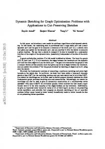
We deployed M OSAIC on PlanetLab to understand the widearea performance effects of using the system. We purposely chose a composed overlay including i3, RON, source routing, and tunneling for legacy applications (all implemented within M OSAIC in 69 Mozlog rules) to bring the Alice example from the introduction and Section 5.4 to a resolution. Our experimental setup is as follows. As our end-host, we used a Linux PC in New Jersey with a high speed cable modem connection as the gateway node, which performed NAT for a Thinkpad X31 laptop. The laptop functioned as our server, using Apache to serve a 21MB file. The file was downloaded from a machine in Utah with a modified version of wget that records the download throughput. These two nodes in New Jersey and Utah, plus three additional nodes (two in the east coast, and one in the west coast), were used to form a private RON network. We further selected 44 PlanetLab nodes, mostly in the US, to run i3. During the experiment, we validated the functionality of resilient routing provided by RON by manually injected network failures via changing the firewall rules on the gateway to block the downloader’s traffic 30 seconds after wget was started; then we unblocked the traffic after another 30 seconds. For the purposes of comparison with the best case scenario, we repeated the same test using direct IP communication. Note that direct IP loses all the benefits of our composed overlay (no resilience, NAT, or mobility support), but achieves the best possible performance. Since our server was behind a NAT, in the direct IP experiment, we had to manually set up a TCP port forwarding rule on the gateway node to reach the Apache server. We repeated multiple runs of the experiments and observed no significant differences.
Figure 6 shows the throughput of the download over time for M OSAIC and DirectIP. Network failures were injected 30 seconds after experiment start, and removed after 30 additional seconds. We make the following observations. First, M OSAIC’s performance over the wide area is respectable: Despite implementing the entire composed overlay (including legacy support for applications using M OSAIC) in Mozlog, we incurred only 20% additional overhead compared to using direct IP, while achieving the benefits of mobility, NAT support and resilient routing. The majority of the overhead comes from the extra packet headers for the composed overlay protocols—an overhead that is repaid with significant functionality. Second, with respect to the functionality of our composed overlay, we were able to achieve successful downloads from a server behind a NAT using M OSAIC. In addition, resilient routing was achieved: Our RON network periodically monitored the link status and recovered from routing failures. Hence, during the period where we injected the routing failures, M OSAIC was able to make a quick recovery from failure, as is shown by the sustained throughput. On the other hand, DirectIP suffered a failure (and hence a drop of throughput to zero) during the 30-60 second period. Overall, M OSAIC finished the download in a shorter time despite lower throughput, due to the resiliency of RON.
7.3
Dynamic Overlay Composition
In our final experiment, we evaluate the dynamic composition capabilities of M OSAIC. Our setup consists of an 8-node cluster, where each node has a similar hardware configuration to the setup in Section 7.1. As a baseline prior to the dynamic switching experiment, we made static comparisons between two composed networks: we executed Chord-over-IP and Chord-over-RON on our cluster, which consists of the Chord overlay on top of IP and RON respectively. Our network size is 16, where each machine executed two instances of the composed overlay nodes. In the steady state, each node periodically issues a lookup request. A lookup is accurate if the results of the lookup are correct, i.e., the results point to the node whose key is the closest successor of the lookup key. Based on this definition, we compute the lookup accuracy rate, which is the fraction of accurate lookups over the duration of each experimental run at every 1 minute interval. Network link failures are emulated by changing the firewall settings in the cluster to drop packets between the selected nodes. Figure 7 shows our evaluation results over a period of 20 minutes, with the first link failure at the 7th minute, then the second link failure at the 10th minute, and the failures recovered at the 16th minute. When the first link failure occurred, we observed that lookup accuracy of Chord-overIP dropped to 93%. The accuracy further dropped to 86% when the second link failure occurred, only to recover when network connectivity was reestablished. On the other hand, Chord-over-RON continued to sustain high lookup accuracy (>99%) even in the face of network failures, due to its ability to find alternative routes quickly. Having compared the composed overlays separately, we next evaluate M OSAIC’s dynamic switching capability, where we started with Chord-over-IP, and then switched our composition to Chord-over-RON after 7 minutes. This dynamic
switching is achieved by merely changing the underlay address of Chord from IP to RON, as described in Section 5.4. Figure 8 shows the resulting lookup accuracy over a period of 15 minutes. We observe that during the process of switching its underlay from IP to RON, Chord continued to sustain high lookup accuracy, demonstrating that M OSAIC is able to performing dynamic switching seamlessly.
8.
RELATED WORK
Composing a plurality of heterogeneous networks was proposed in Metanet [31], and also examined in Plutarch [6]. Oasis [19] and OCALA [11] provide legacy support for multiple overlays. Oasis picks the best single overlay for performance. OCALA proposes a mechanism to stitch (similar to M OSAIC’s bridge functionality) multiple overlay networks at designated gateway nodes to leverage functionalities from different overlays. In contrast, M OSAIC’s primary focus is on overlay specification and composition within a single framework. Compared to OCALA, M OSAIC’s declarative framework for composing overlays dynamically is a major step forward compared to the hand-coded approach of OCALA. In addition, M OSAIC also provides support for layering in addition to bridging.M OSAIC is not limited to IPbased networks, supports dynamic composition, and routing primitives such as unicast and multicast. These benefits result in better extensibility and evolvability of M OSAIC over existing composition systems. M OSAIC aims to reduce the complexity of building and deploying network protocols, through declarative high-level specifications. In a similar spirit, overlay network specifications (e.g. P2 [16] and MACEDON [27]), and network configuration frameworks (e.g. CONMan [4]) aims to achieve similar goals in complementary domains. CONMan uses a protocol independent configuration framework based on modules and pipes. An interesting area of future research is to work towards a unified declarative framework for implementing and configuring networks across all levels.
9.
CONCLUSIONS AND FUTURE WORK
M OSAIC is an extensible infrastructure that enables the specification of new overlay networks, and also dynamic composition of such overlays. M OSAIC provides declarative networking: it uses a unified declarative language (Mozlog) to specify new overlay networks, and a novel runtime to enable composition in both the control and data planes. We demonstrated M OSAIC’s composition capabilities via deployment and measurement on both a local cluster and the PlanetLab testbed, and showed that the performance overhead of M OSAIC is respectable compared to native implementations, while achieving the benefits of overlay composition. Several new directions appear promising. First, we are exploring techniques for automatic overlay composition, given application requirements, overlay properties and constraints. Second, we are further investigating the use of our declarative framework for correctness checks and for making inferences about the compositions and their attributes, particularly for reasoning about feature interactions among different overlays. Third, we are exploring adding mechanisms for extensible transport and session layer overlays [20, 15, 33]. Such extensibility will be useful in the context of mobile computing, and in environments where there is a high
300 Mosaic Direct IP
1
1
200
150
100
50
lookup accuracy
lookup accuracy
throughput KB/s
250
0.8 0.6 0.4 0.2
0
20
40
60 80 100 elapsed time (second)
120
140
Figure 6: Throughput comparison between overlay composition in Mosaic vs direct IP connection during network failure.
0 0
5
10 15 time (minute)
[18]
[19]
10.
20
Figure 7: Lookup accuracy comparison between Chord over IP and Chord over RON.
degree of network and device heterogeneity during an application session. Finally, we are also exploring better ways to compose and share at finer granularity, by combining individual feature sets from multiple overlays to meet application needs.
REFERENCES
[1] D. Andersen, H. Balakrishnan, M. Kaashoek, and R. Morris. Resilient overlay networks. In Proc. SOSP, 2001. [2] H. Balakrishnan, M. F. Kaashoek, D. Karger, R. Morris, and I. Stoica. Looking Up Data in P2P Systems. Communications of the ACM, Vol. 46, No. 2, Feb. 2003. [3] H. Balakrishnan, K. Lakshminarayanan, S. Ratnasamy, S. Shenker, I. Stoica, and M. Walfish. A Layered Naming Architecture for the Internet. In Proc. SIGCOMM, 2004. [4] H. Ballani and P. Francis. CONMan: A Step Towards Network Manageability. In SIGCOMM, 2007. [5] D. Clark, C. Partridge, J. C. Ramming, and J. Wroclawski. A Knowledge Plane for the Internet. In Proceedings ACM SIGCOMM Conference, Karlsruhe, Germany, August 2003. [6] J. Crowcroft, S. Hand, R. Mortier, T. Roscoe, and A. Warfield. Plutarch: An Argument for Network Pluralism. In Proc. FDNA, 2003. [7] J. R. Douceur and J. Howell. Distributed directory service in the farsite file system. In OSDI, pages 321–334, 2006. [8] M. Freedman, K. Lakshminarayanan, and D. Mazieres. OASIS: Anycast for any service. In Proc of NSDI, 2006. [9] M. J. Freedman, K. Lakshminarayanan, S. Rhea, and I. Stoica. Non-Transitive Connectivity and DHTs. In Proc. of the Second Workshop on Real, Large Distributed Systems (WORLD’05), 2005. [10] K. P. Gummadi, H. Madhyastha, S. D. Gribble, H. M. Levy, , and D. J. Wetherall. Improving the reliability of internet paths with one-hop source routing. In OSDI, 2004. [11] D. Joseph, J. Kannan, A. Kubota, K. Lakshminarayanan, I. Stoica, and K. Wehrle. OCALA: An architecture for supporting legacy applications over overlays. In Proc. NSDI, 2006. [12] D. Katabi and J. Wroclawski. A framework for scalable global IP-anycast (GIA). In SIGCOMM, 2000. [13] A. Keromytis, V. Misra, and D. Rubenstein. SOS: Secure overlay services. In Proc. SIGCOMM, 2002. [14] E. Kohler, R. Morris, B. Chen, J. Jannotti, and M. F. Kaashoek. The Click Modular Router. ACM Transactions on Computer Systems, 18(3):263–297, 2000. [15] Y. Li, Y. Zhang, L. Qiu, and S. S. Lam. SmartTunnel: Achieving reliability in the internet. In INFOCOM, 2007. [16] B. T. Loo, T. Condie, J. M. Hellerstein, P. Maniatis, T. Roscoe, and I. Stoica. Implementing Declarative Overlays. In Proc. SOSP, 2005. [17] B. T. Loo, J. M. Hellerstein, I. Stoica, and R. Ramakrishnan.
[20] [21]
[22] [23] [24] [25] [26] [27]
[28] [29] [30] [31] [32] [33]
[34]
0.6 0.4 0.2
chord over IP chord over RON
0
0.8
0 0
chord over IP chord over RON 5 10 time (minute)
15
Figure 8: Chord lookup performance during dynamic underlay network switching from IP to RON.
Declarative Routing: Extensible Routing with Declarative Queries. In Proc. SIGCOMM, 2005. H. V. Madhyastha, T. Isdal, M. Piatek, C. Dixon, T. Anderson, A. Krishnamurthy, and A. Venkataramani. iplane: An information plane for distributed services. In Proc. OSDI, Nov 2006. H. V. Madhyastha, A. Venkataramani, A. Krishnamurthy, and T. Anderson. Oasis: An Overlay-Aware Network Stack. In Operating Systems Review, pages 41–48, 2006. Y. Mao, B. Knutsson, H. Lu, and J. M. Smith. DHARMA: Distributed Home Agent for Robust Mobile Access. In IEEE INFOCOM, 2005. Y. Mao, B. T. Loo, Z. Ives, and J. M. Smith. MOSAIC: Unified Platform for Dynamic Overlay Selection and Composition. University of Pennsylvania CIS Technical Report No. MS-CIS-08-21, 2008. A. Nakao, L. Peterson, and A. Bavier. A Routing Underlay for Overlay Networks. In Proc. SIGCOMM, 2003. L. Peterson, S. Shenker, and J. Turner. Overcoming the Internet Impasse Through Virtualization. In HotNets-III, 2004. PlanetLab. Global testbed. http://www.planet-lab.org/. R. Ramakrishnan and J. D. Ullman. A Survey of Research on Deductive Database Systems. Journal of Logic Programming, 23(2):125–149, 1993. S. Rhea, B. Godfrey, B. Karp, J. Kubiatowicz, S. Ratnasamy, S. Shenker, I. Stoica, and H. Yu. Opendht: a public dht service and its uses. In Proc. SIGCOMM, 2005. A. Rodriguez, C. Killian, S. Bhat, D. Kostic, and A. Vahdat. MACEDON: Methodology for Automatically Creating, Evaluating, and Designing Overlay Networks”. In Proc. of NSDI, March 2004. Skype. Skype P2P Telephony. 2006. http://www.skype.com. I. Stoica, D. Adkins, S. Zhuang, S. Shenker, and S. Surana. Internet Indirection Infrastructure. In Proc. SIGCOMM, 2002. A. Vahdat and D. Becker. Epidemic routing for partially-connected ad hoc networks. Duke Technical Report CS-2000-06, 2000. J. T. Wroclawski. The Metanet. In Proc. Workshop on Research Directions for the Next Generation Internet, 1997. J. Yonan. OpenVPN: Building and Integrating Virtual Private Networks. http://www.openvpn.net. M. Zhang, J. Lai, A. Krishnamurthy, L. Peterson, and R. Wang. A transport layer approach for improving end-to-end performance and robustness using redundant paths. In Proc of USENIX ATC, 2004. S. Q. Zhuang, K. Lai, I. Stoica, R. H. Katz, and S. Shenker. Host Mobility using an Internet Indirection Infrastructure. In ACM/Usenix Mobisys, 2003.