THE PUBLISHING HOUSE OF THE ROMANIAN ACADEMY
PROCEEDINGS OF THE ROMANIAN ACADEMY, Series A, Volume 12, Number 3/2011, pp. 249–256
MOTION CUEING: FROM DESIGN UNTIL IMPLEMENTATION
Alina CAPUSTIAC1, Dorel BANABIC2, Dieter SCHRAMM2, Udo OSSENDOTH3 1
Technical University of Cluj-Napoca, Romania University of Duisburg-Essen, Germany 3 Fachhochschule Gelsenkirchen, Germany E-mail:
[email protected]
2
Driving simulators are tools used for driver education, behavioural evaluation and to prove new systems. In order to be effective, the driving simulators have to provide correct and realistic cues. Due to the research conducted at the Chair of Mechatronics from University of Duisburg-Essen, on human machine interface, a low cost driving simulator with 3 degrees of freedom was designed. This paper presents a control strategy for this tool with the goal of increasing the authenticity degree of the simulation. The models used are presented and discussed. Experimental results, limitations and overview of the work are concluding this contribution. Key words: Driving simulator, Real time simulation, Motion cueing.
1. INTRODUCTION Regardless of their application domain, driving simulators are virtual reality tools designed to offer a realistic driving experience. Due to the workspace and actuators limitations, the driving simulators cannot perfectly reproduce the motion of the vehicle being simulated. Different strategies are used in order to immerse the driver in the simulation environment and to increase the degree of authenticity of the simulation: motion cueing [1], a completely enclosed environment [2], a large field of view [3], visual and audio cues, etc. The driving task was often described in the literature as a visual task, due to the significant amount of information the driver is collecting while driving, through the visual channels [5]. However, recent research claims that the human driver uses other channels also, for spatial-temporary information [6]. The motion is sensed by the human through the vestibular organs and skin. The vestibular system is sensitive to the accelerations applied on the human body and its role is to transfer information about these accelerations to the brain and to keep the spatial orientation of the head [7]. The skin and tissues through pressure and tissues sensitivity to high frequency vibrations also offers important information about the motion to the body [8]. A complete understanding of the human motion perception is crucial in order to provide a realistic simulation environment. Once the human perception of movement and the driver’s implication in its decisions is understood, the importance of introducing motion cues in a driving simulator is emphasized. There are different actuation mechanisms used and described in the literature, from which the Stewart platform is the most often used [9]. It is assumed that a high level simulator offers a more realistic experience as a mid-level simulator due to the fact that the fidelity of a driving simulator increases with the number of situations reproduced that occurs also in reality [10]. However, Denne stated in [2] that the degrees of freedom (dof) roll, pitch and heave are normally adequate for leisure simulation. The same author claims that the yaw motion is not required to be simulated, due to the fact that the small rotations have no physiological effect and can be considered equivalent to the human head’s rotations. There are different methods that can be used to couple the available motion. A turn to the left will be felt by the driver as an inertial force to the right. The forward acceleration can be reproduced by tilting the platform backwards so that the gravity acceleration is felt in the back. The centrifugal force can be obtained by combining the pitch and roll angle to couple into the gravity vector. The sideways acceleration can be simulated by roll motion
250
Alina Capustiac, Dorel Banabic, Dieter Schramm, Udoo Ossendoth
2
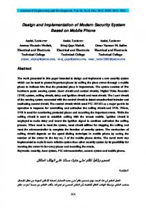
[2]. The motion cueing strategy, the term used in the literature for the sensation if the motion [11] was first used for aircraft simulators [12]. There has been done significant research in this field. The classical motion cueing algorithms have a simple architecture and consist of low and high pass filters [13]. The disadvantage of these algorithms is that their parameters are kept constant during the simulation. The adaptive algorithms were developed in order to overcome this disadvantage and the filters are replaced with time varying gains [14]. The optimal algorithms solve a transfer function that relates the vehicle’s rotations and accelerations with the ones that should be applied to the platform, such that the difference between the felt signals in both is minimized [13]. In the frame of a cooperation between the Technical University of Cluj-Napoca, the University of Duisburg-Essen and the Fachhochschule Gelsenkirchen, Germany a study on the authenticity degree of the 3 dof simulator was made. The degrees of freedom of the system are: rotation about x axis, rotation about y axis and translation along z axis. Figure 1 presents the scheme implemented in this work.
Fig. 1 – The overall control strategy implemented.
The driver is interacting with the simulator by means of steering wheel and pedals. This data is transmitted in real time to the vehicle models implemented in Matlab/Simulink. The accelerations and velocities calculated by these models are used as inputs for the motion cueing algorithms. With the help of the inverse kinematics of the motion platform, the strokes of the actuators are obtained. After being processed, the information is being sent to the actuators, via UDP communication. A study with 26 participants was performed in order to establish the degree of authenticity of the simulator. 2. SIMULATION MODELS 2.1. Vehicle Model The vehicle model considers a simple vehicle suspension. The wheels are connected through spring and damper elements to the vehicle chassis. The wheel centres can only move perpendicular to the road [19]. This means that complex wheel suspension characteristics like camber and caster change are neglected. However, this model is complex enough for spatial vehicle dynamic analysis and for being a basis model for a driving simulator. The considered dof of the vehicle model are listed in Table 1 and shown in Fig. 2.
Fig. 2 – DOF of the spatial twin track mode.
3
Motion Cueing: From Design Until Implementation
251
Table 1 DOF of the spatial vehicle model Notation
Description
xv, yv, zv ψv, θv, φv φRi, i = 1, ..., 4 zRi, i = 1, ..., 4
Coordinates of the vehicle’s centre of gravity Cardan shaft angle of the vehicle body Rotation of the wheel about its roll axis Vertical movement of the wheel
2.2. Motion Cueing The classical strategy was proposed and studied in this contribution. These algorithms consist of high and low pass filters which are computing the accelerations of the motion base along any degree of freedom. The low pass filters are used in order to remove the low frequencies, considered to bring the platform to its limitation [1]. As stated before, the disadvantage represents this ‘worst case scenario’ design of the filters [15]. The motion cueing strategy implemented in this paper is presented in Fig. 3.
Fig. 3 – The classical motion cueing strategy implemented.
The longitudinal and lateral accelerations are scaled, low pass filtered and used in the tilt coordination process. This strategy reproduces accelerations by coupling the gravitational vector [4]. The human driver will detect this motion as negative or positive acceleration, depending on the inclinations direction. The tilt angles α, are calculates as follows:
a α roll = a sin lateral , g alongitudinal α pitch = a sin . g
(1)
(2)
The design of this strategy has to take in consideration the human motion thresholds. The tilting of the platform has to be done slow enough so the human cannot perceive the rotation, so a rate limiter was implemented. In this work, the thresholds described by Meiry in [7] were used and are given in Table 2. Table 2 The motion thresholds used in simulation [7] Motion Roll Pitch Heave
Values 3 3.6 0.01g
Units °/s °/s m/s2
252
Alina Capustiac, Dorel Banabic, Dieter Schramm, Udoo Ossendoth
4
The roll and pitch rate are scaled with respect to the available workspace and then high pass filtered, integrated and then added to the resulted tilted angles in order to obtain the pitch, respectively roll angle. The vertical acceleration is high pass filtered; a rate limitation is applied, obtaining the vertical displacement of the platform. The parameters describing these filters were calculated with respect to the available workspace and human motion thresholds, following the approach proposed in [16]. Considering a low pass filter: axvehicle k , = 2 axLF s + 2ςωn s + ωn2
(3)
where ωn is the natural pulsation, ζ is the damping coefficient, k represents the scaling factor and s is the Laplace coefficient. The constraint equations applied were:
k ξωn < Wmax , k ξ2 ωn2 < vt
(4)
k ξ3ω3n < at where Wmax is the maximum displacement allowed by the motion platform, vt is the velocity human threshold and at is the acceleration human threshold and ξ is defined as: ς ξ = exp ln(ς − ς 2 − 1) . 2 ς −1
(5)
Figure 4 shows the output of the low pass second order filter, while inputting the longitudinal acceleration registered for a braking manoeuvre. It can be observed how the second order filter works, attenuating high frequency accelerations. After calculating all the parameters for the motion cueing filters, the Laplace transfer functions were discretized, in order to be used in real time simulations, with the help of xPC Target [17].
Fig. 4 – The output of the second order low pass filter (simulation results).
3. MOTION SYSTEM
The 3 dof motion system used in this paper consists of a cockpit actuated by 3 linear actuators, as can be seen in Fig. 5. The maximum roll angle is ±7°, the maximum pitch angle is ±7° and the maximum heave displacement is ±0.175 m. The actuators maximum velocity is 1 m/s.
5
Motion Cueing: From Design Until Implementation
253
Fig. 5 – The 3 dof simulator.
The inverse kinematics was calculated as follows: 0 sθ cθ sϕ ⋅ sθ cϕ − sϕ ⋅ cθ H = − sθ ⋅ cθ sϕ cϕ ⋅ cθ 0 0 0
0 0 z 1
(6)
Ai = H ⋅ Ainitial i , i = 1,...,3 ,
where c and s denote cos and sin, θ and φ are the Euler’s angles (pitch, respectively roll), z is the heave displacement of the vehicle’s centre of gravity, Ainitial i represents the initial coordinates of the mobile platform and Ai represents the final coordinates of the mobile platform.
Fig. 6 – The 3 dof simulator’s workspace.
4. RESULTS
The goal of this contribution was to implement the vehicle models designed together with the motion cueing in real time and to investigate the degree of authenticity that such a simulation can reproduce. The visualization of the environment is done with the help of a commercial game engine. This ensures a high level of realism and an easy adaption of scenarios. A multi-body model is used to derive the steering wheel torque in real-time and a DC motor is then used to generate exactly that torque at the steering wheel. This
254
Alina Capustiac, Dorel Banabic, Dieter Schramm, Udoo Ossendoth
6
force-feedback steering wheel has already been used during the design of lane-keeping assistance systems and other studies and its realism has been shown during these studies [18]. The correct pedal feeling is achieved by using the original vehicle pedals and the original brake booster support. The classical motion cueing algorithms were design in order to obtain a realistic driving feeling as possible. 26 drivers with age between 21 and 46 participated in our study. They were asked to drive first a 4–5 minutes drive in order to get adjusted to the simulation environment. Then they were asked to drive an ISO lane change maneuver and a city scenario drive. After completing the driving tasks, each participant answered 18 questions in order to gain the statistical information needed. 50% percent of the participated rated the authenticity of the motion with 60%, when 100% represents the feeling of motion sensed in a real vehicle driving situation. 30% of the participants rated the motion with 70% percent and the rest of the participants rated the motion reproduced in the driving simulator with 80% or more. 85% percent of the participants rated their adjustment to the simulated environment as fast or very fast, and 15% stated that the adjustment was slow. None of the participants experienced simulation sickness and 23 of the participants stated that it was easy or very easy for them to perform the required driving tasks. Figure 7 shows the power spectral density of the signals obtained from the two track model. It can be observed the frequency attenuation of the longitudinal acceleration.
Fig. 7 – The frequency nature of the ax acceleration obtained from the vehicle model.
Figure 8 shows the strokes for the three actuators of the driving simulator while driving in a city scenario.
Fig. 8 – The 3 linear actuators strokes.
7
Motion Cueing: From Design Until Implementation
255
5. CONCLUSIONS
Defining a function ‘to be simulated’ in a driver simulator is still a challenging and not completely solved problem. Due to the motion systems limitations, reproducing exactly the accelerations felt by the driver is impossible. The question that follows is which cues are important for the driver and which have to be reproduced. It is hard to find an extensive work about the driving simulators limitations. We propose a 3 dof low cost solution with the goal of understanding the human’s perception of motion and the systems limitations. A classical approach of the motion cueing strategy is discussed and implemented in this contribution with fine results. The tilting coordination strategy had proved to be helpful, mostly in the large curves drove by the participants. By direct 100% breaking, some vibrations occurred in the steering wheel, problem that will be optimized in the vehicle model. In order to use more efficient the workspace available, an adaptive strategy will also be studied and implemented in the future work. REFERENCES 1. 2. 3. 4. 5. 6. 7. 8. 9. 10. 11. 12. 13. 14. 15. 16. 17. 18. 19.
Telban, R., Cardullo, F., Motion cueing algorithm development: human centred linear and nonlinear approaches, NASA Report. 213747, 2005. Denne, P., Simulators for leisure – A new industry, IEE Conference on Simulation, 1986. Baron, S., Lancraft, R., Zacharias, G., Pilot/Vehicle Model Analysis of Visual and Motion Cue Requirements in Flight Simulation, NASA, Report 3312, 1980. Motionbase Ltd, Guide to the Motionbase motion cueing algorithms, Document 00064500, 1999. Durkee, S.M., The effect of Simulation Attributes on Driver Perception and Behaviour, Master of Science Thesis, Montana State University, 2010. Kemeny, A., Penerai, F., Evaluation perception in driving simulation experiments, in Trends in Cognitive Sciences, 7, 1, 2003. Meiry, J., The vestibular system and human dynamic space orientation, PhD thesis, Massachusetts Institute of Technology, 1958. Young, L.R. Perception of the Body in Space: Mechanisms, in Handbook of Physiology – The Nervous System III, pp. 1023– 1066, 1982. Tu, K.Y, Wu, T.C, Lee, T.T., A study of Stewart platform specifications for motion cueing system, in Systems, Man and Cybernetics, 2004 IEEE International Conference, vol. 4, pp. 3950–3955. Godley, S.T., Triggs, T.J., Fildes, B.N., Driving simulator validation for speed research, Accident Analysis and Prevention, 34/589–600, 2002. Arioui, H., Hima, S., Nehaoua, L., 2 DOF Low Cost Platform for Driving Simulator: Modeling and Control, 2009 IEEE/ASME International Conference and Advanced Intelligent Mechatronics, Singapore, 2009. Jamson, H. Driving simulation validity: issues of field of view and resolution, Proceedings of Driving Simulators Conference, Paris, France, pp. 57-64, 2000. Nehaoua, L., Arioui, H., Espie, S., Mohellebi, H., Motion cueing algorithms for small driving simulator, Orlando, Florida, May 2006, IEEE International Conference on Robotics and Automation. Loureiro, B., Motion cueing in the Chalmers Driving Simulator. A model predictive approach, Master of Science Thesis, Chalmers University of Technology., 2009. Parrish, R., Martin, D., Evaluation of a linear washout for simulator motion cue representation during landing approach, NASA technical note, D-8036, 1975. Nehaoua, L., Arioui, H., Mohellebi, H., Espie, S., Restitution Movement for a Low Cost Driving Simulator, Proceedings of the American Control Conference, USA, 2006. *** http://www.mathworks.com/products/xpctarget/, April, 2011. Hesse, B., Hiesgen, G., Brandt, T., Schramm, D., A Driving Simulator as a Tool for the early Characteristics Validation of Human-Centered Mechatronic Systems, Proceedings of VDI Mechatronik, 2009, pp.109-116. Schramm, D., Hiller, M., Bardini, R.,. Modellbildung Und Simulation der Dynamik Von Kraftfahrzeugen, Springer, 2010.
Received May 25, 2011


![[PDF] Until Ashlyn: (Until Her) - Google Sites](https://m.moam.info/img/260x300/pdf-until-ashlyn-until-her-google-sites_647814ce097c4786708c6d05.jpg)