MPEG Video Compression Basics. B.G. Haskell and A. Puri. 1 If the camera rate,
chosen to portray motion, is below the display rate, chosen to avoid flicker,.
Chapter 2
MPEG Video Compression Basics B.G. Haskell and A. Puri
2.1
Video Coding Basics
Video signals differ from image signals in several important characteristics. Of course the most important difference is that video signals have a camera frame rate of anywhere from 15 to 60 frames/s, which provides the illusion of smooth motion in the displayed signal.1 Another difference between images and video is the ability to exploit temporal redundancy as well as spatial redundancy in designing compression methods for video. For example, we can take advantage of the fact that objects in video sequences tend to move in predictable patterns, and can therefore be motion-compensated from frame-to-frame if we can detect the object and its motion trajectory over time. Historically, there have been five major initiatives in video coding [1–5] that have led to a range of video standards. s Video coding for ISDN video teleconferencing, which has led to the ITU video coding standard called H.261 [6]. H.261 is also the baseline video mode for most multimedia conferencing systems. s Video coding for low bitrate video telephony over POTS2 networks with as little as 10 kbits/s allocated to video and as little as 5.3 kbits/s allocated to voice coding, which led to the ITU video coding standard called H.263 [7]. The H.263 low bitrate video codec is used at modem rates of from 14.4 to 56 kbits/s, where the modem rate includes video coding, speech coding, control information, and other logical channels for data.
1 If the camera rate, chosen to portray motion, is below the display rate, chosen to avoid flicker, then some camera frames will have to be repeated. 2 Plain Old Telephone Service.
B.G. Haskell (*) Apple Computer, 1 Infinite Loop, Cupertino, CA 95014, USA e-mail:
[email protected] L. Chiariglione (ed.), The MPEG Representation of Digital Media, DOI 10.1007/978-1-4419-6184-6_2, © Springer Science+Business Media, LLC 2012
7
8
B.G. Haskell and A. Puri
s Video coding for storing movies on CD-ROM with on the order of 1.2 Mbits/s allocated to video coding and 256 kbits/s allocated to audio coding, which led to the initial ISO MPEG-1 (Motion Picture Experts Group) standard [8]. s Video coding for broadband ISDN, broadcast and for storing video on DVD (Digital Video Disks) with on the order of 2–400 Mbits/s allocated to video and audio coding, which led to the ISO MPEG-2 video coding standard [9]. The ITU has given this standard the number H.262. s Video coding for object-based coding at rates as low as 8 kbits/s, and as high as 1 Mbits/s, or higher, which led to the ISO MPEG-4 video coding standard [10]. Key aspects of this standard include independent coding of objects in a picture; the ability to interactively composite these objects into a scene at the display; the ability to combine graphics, animated objects, and natural objects in the scene; and finally the ability to transmit scenes in higher dimensionality formats (e.g., 3D). Before delving in to details of standards, a few general remarks are in order. It is important to note that standards specify syntax and semantics of the compressed bit stream produced by the video encoder, and how this bit stream is to be parsed and decoded (i.e., decoding procedure) to produce a decompressed video signal. However, many algorithms and parameter choices in the encoding are not specified (such as motion estimation, selection of coding modes, allocation of bits to different parts of the picture, etc.) and are left open and depend greatly on encoder implementation. However it is a requirement that resulting bit stream from encoding be compliant to the specified syntax. The result is that the quality of standards based video codecs, even at a given bitrate, depends greatly on the encoder implementation. This explains why some implementations appear to yield better video quality than others. In the following sections, we provide brief summaries of each of these video standards, with the goal of describing the basic coding algorithms as well as the features that support use of the video coding in multimedia applications.
2.1.1
Basics of Interframe Video Coding
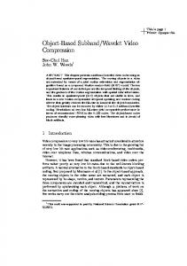
A video scene captured as a sequence of frames can be efficiently coded by estimating and compensating for motion between frames prior to generating interframe difference signal for coding. Since motion compensation is a key element in most video coders, it is worthwhile understanding the basic concepts in this processing step. For the ease of processing, each frame of video is uniformly partitioned into smaller units called Macroblocks (MBs, formally defined a bit later) where each macroblock consists of a 16 × 16 block of luma, and corresponding chroma blocks. The way that the motion estimator works is illustrated in Fig. 2.1. Each block of pixels (say 16 × 16 luma block of a MB) in the current frame is compared with a set of candidate blocks of same size in the previous frame to determine the one that best predicts the current block. The set of blocks includes those within a search region in previous frame centered on the position of current block in the current frame.
2 MPEG Video Compression Basics
9
A’ A
mv
previous frame
current frame
Fig. 2.1 Motion compensation of interframe blocks %.#/$%2 2D DCT
Variable Length Encoder
Quant.
Buffer
Inv. Quant. Inv. 2D DCT
Motion Compensated Predictor
MOTION VECTORS
Motion Estimator $%#/$%2 Buffer
Variable Length Decoder MOTION VECTORS
Inv. Quant.
Inv. 2D DCT
Motion Compensated Predictor
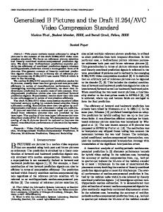
Fig. 2.2 Motion compensated encoder/decoder for interframe coding
When the best matching block is found, a motion vector is determined, which specifies the reference block. Figure 2.2 shows a block diagram of a motion-compensated image codec. The key idea is to combine transform coding (in the form of the Discrete Cosine Transform (DCT) of 8 × 8 pixel blocks) with predictive coding (in the form of
10
B.G. Haskell and A. Puri
differential Pulse Code Modulation (PCM)) in order to reduce storage and computation of the compressed image, and at the same time to give a high degree of compression and adaptability. Since motion compensation is difficult to perform in the transform domain, the first step in the interframe coder is to create a motion compensated prediction error in the pixel domain. For each block of current frame, a prediction block in the reference frame is found using motion vector found during motion estimation, and differenced to generate prediction error signal. This computation requires only a single frame store in the encoder and decoder. The resulting error signal is transformed using 2D DCT, quantized by an adaptive quantizer, entropy encoded using a Variable Length Coder (VLC) and buffered for transmission over a fixed rate channel. We now discuss how various MPEG standards are built using principles and building blocks discussed so far.
2.2
The MPEG-1 Video Coding Standard
The MPEG-1 standard is the first true multimedia standard with specifications for coding, compression, and transmission of audio, video, and data streams in a series of synchronized, mixed Packets. The driving focus of the standard was storage of multimedia content on a standard CDROM, which supported data transfer rates of 1.4 Mb/s and a total storage capability of about 600 MB. MPEG-1 was intended to provide VHS VCR-like video and audio quality, along with VCR-like controls. MPEG-1 is formally called ISO/IEC 11172.
2.2.1
Requirements of the MPEG-1 Video Standard
Uncompressed digital video of full component TV resolution requires a very high transmission bandwidth, while VHS VCR-grade equivalent raw digital video requires transmission bandwidth of around 30 Mbits/s, with compression still necessary to reduce the bit-rate to suit most applications. The required degree of compression is achieved by exploiting the spatial and temporal redundancy present in a video signal. However, the compression process is inherently lossy, and the signal reconstructed from the compressed bit stream is not identical to the input video signal. Compression typically introduces some artifacts into the decoded signal. The primary requirement of the MPEG-1 video standard was that it should achieve the high quality of the decoded motion video at a given bit-rate. In addition to picture quality under normal play conditions, different applications have additional requirements. For instance, multimedia applications may require the ability to randomly access and decode any single video picture3 in the bitstream. Also, the ability to perform fast
3
Frames and pictures are synonymous in MPEG-1.
2 MPEG Video Compression Basics
11
search directly on the bit stream, both forward and backward, is extremely desirable if the storage medium has “seek” capabilities. It is also useful to be able to edit compressed bit streams directly while maintaining decodability. And finally, a variety of video formats were needed to be supported.
2.2.2
H.261 Coding Concepts as Applicable to MPEG-1 Video
The H.261 standard employs interframe video coding that was described earlier. H.261 codes video frames using a DCT on blocks of size 8 × 8 pixels, much the same as used for the original JPEG coder for still images. An initial frame (called an INTRA frame) is coded and transmitted as an independent frame. Subsequent frames, which are modeled as changing slowly due to small motions of objects in the scene, are coded efficiently in the INTER mode using a technique called Motion Compensation (MC) in which the displacement of groups of pixels from their position in the previous frame (as represented by so-called motion vectors) are transmitted together with the DCT coded difference between the predicted and original images. 2.2.2.1
H.261 Bitstream Data Hierarchy
We will first explain briefly the data structure in an H.261 video bit stream and then the functional elements in an H.261 decoder. Only two picture formats, common intermediate format (CIF) and quarter-CIF (QCIF), are allowed. CIF pictures are made of three components: luminance Y and color differences Cb and Cr, as defined in ITU-R Recommendation BT601. The CIF picture size for Y is 352 pels4 per line by 288 lines per frame. The two color difference signals are subsampled to 176 pels per line and 144 lines per frame. The image aspect ratio is 4(horizontal):3(vertical), and the picture rate is 29.97 non-interlaced frames per second. All H.261 standard codecs must be able to operate with QCIF; CIF is optional. A picture frame is partitioned into 8 line × 8 pel image blocks. A Macroblock (MB) is defined as four 8 × 8 (or one 16 × 16) Y block/s, one Cb block, and one Cr block at the same location. The compressed H.261 video bit stream contains several layers. They are picture layer, group of blocks (GOB) layer, Macroblock (MB) layer, and block layer. The higher layer consists of its own header followed by a number of lower layers. Picture Layer In a compressed video bit stream, we start with the picture layer. Its header contains: Picture start code (PSC) a 20-bit pattern.
4
Abbreviation of pixel.
12
B.G. Haskell and A. Puri
Temporal reference (TR) a 5-bit input frame number. Type information (PTYPE) such as CIF/QCIF selection. Spare bits to be defined in later versions. GOB Layer At the GOB layer, a GOB header contains: s Group of blocks start code (GBSC) a 16-bit pattern. s Group number (GN) a 4-bit GOB address. s Quantizer information (GQUANT) initial quantizer step size normalized to the range 1–31. At the start of a GOB, we set QUANT = GQUANT. s Spare bits to be defined in later versions of the standard. Next, comes the MB layer. An 11-bit stuffing pattern can be inserted repetitively right after a GOB header or after a transmitted Macroblock. Macroblock (MB) Layer At the MB layer, the header contains: s Macroblock address (MBA) location of this MB relative to the previously coded MB inside the GOB. MBA equals one plus the number of skipped MBs preceding the current MB in the GOB. s Type information (MTYPE) 10 types in total. s Quantizer (MQUANT) normalized quantizer step size to be used until the next MQUANT or GQUANT. If MQUANT is received we set QUANT = MQUANT. Range is 1–31. s Motion vector data (MVD) differential displacement vector. s Coded block pattern (CBP) indicates which blocks in the MB are coded. Blocks not coded are assumed to contain all zero coefficients. Block Layer The lowest layer is the block layer, consisting of quantized transform coefficients (TCOEFF), followed by the end of block (EOB) symbol. All coded blocks have the EOB symbol. Not all header information need be present. For example, at the MB layer, if an MB is not Inter motion-compensated (as indicated by MTYPE), MVD does not exist. Also, MQUANT is optional. Most of the header information is coded using Variable Length Codewords. There are essentially four types of coded MBs as indicated by MTYPE: s Intra – original pels are transform-coded. s Inter – frame difference pels (with zero-motion vectors) are coded. Skipped MBs are considered inter by default.
2 MPEG Video Compression Basics
13
s Inter_MC – displaced (nonzero-motion vectors) frame differences are coded. s Inter_MC_with_filter – the displaced blocks are filtered by a predefined loop filter, which may help reduce visible coding artifacts at very low bit rates.
2.2.2.2
H.261 Coding Semantics
A single-motion vector (horizontal and vertical displacement) is transmitted for one Inter_MC MB. That is, the four Y blocks, one Cb, and one Cr block all share the same motion vector. The range of motion vectors is +− 15 Y pels with integer values. For color blocks, the motion vector is obtained by halving the transmitted vector and truncating the magnitude to an integer value. Motion vectors are differentially coded using, in most cases, the motion vector of the MB to the left as a prediction. Zero is used as a prediction for the leftmost MBs of the GOB, and also if the MB to the left has no motion vector. The transform coefficients of either the original (Intra) or the differential (Inter) pels are ordered according to a zigzag scanning pattern. These transform coefficients are selected and quantized at the encoder, and then coded using variable-length codewords (VLCs) and/or fixed-length codewords (FLC), depending on the values. Just as with JPEG, successive zeros between two nonzero coefficients are counted and called a RUN. The value of a transmitted nonzero quantized coefficient is called a LEVEL. The most likely occurring combinations of (RUN, LEVEL) are encoded with a VLC, with the sign bit terminating the RUN-LEVEL VLC codeword. The standard requires a compatible IDCT (inverse DCT) to be close to the ideal 64-bit floating point IDCT. H.261 specifies a measuring process for checking a valid IDCT. The error in pel values between the ideal IDCT and the IDCT under test must be less than certain allowable limits given in the standard, e.g., peak error