MPLS Multicast Traffic Engineering Ali Boudani∗ , Bernard Cousin∗ IRISA/INRIA Rennes∗ Campus Universitaire de Beaulieu, Avenue du G´en´eral Leclerc, 35042 Rennes, France Tel: +33 2 99 84 25 37, Fax: +33 2 99 84 25 29 {aboudani, bcousin}@irisa.fr
Jean-Marie Bonnin∗# ENST Bretagne# CS 17607 2, rue de la chˆataigneraie, 35512 Cesson S´evign´e Tel: +33 2 99 12 70 07, Fax: +33 2 99 12 70 30
[email protected]
Abstract— In this paper, we present multicast traffic engineering and we compare it to unicast traffic engineering. We study the advantages given by the integration of multicasting and MPLS. We present current proposals for multicast traffic engineering and using MPLS network. We describe our approach, the MPLS multicast tree (MMT) protocol. In order to reduce forwarding states and enhance scalability, MMT utilizes MPLS LSPs between branching routers of the multicast tree. We present a simulator for MMT and finally we discuss some simulation results. 1
second the larger number of application members. Multicasting is a useful service to support such applications. When a multicast service is used to send a packet to several destinations, a single transmission is required on any link of the multicast tree associated to the application; while several independent transmissions would be required using unicast service. MPLS [1] as a traffic engineering tool has emerged as an elegant solution to meet the requirements of the backbone networks of the Internet. Multicast and MPLS are two complementary technologies: multicast trees could be supported by MPLS networks. MPLS will enhance the network performance and present an efficient solution for multicast scalability and control overhead problems. Multicast attempts to conserve network bandwidth, while traffic engineering attempts to provision the bandwidth in an appropriate fashion to users.
I. I NTRODUCTION Best-effort service model existing in the current Internet is inadequate in meeting the growing demands of the next generation applications. These applications require QoS guarantees and effective data delivery. In consequence, the network is required to provide various qualities of service (QoS) for applications sensitive to delay, jitter and packet loss. In order to provide QoS to users across the Internet, either we could increase the bandwidth available in the network such that the extra capacity allows all users to meet their appropriate QoS, or we should suppose that bandwidth is limited and therefore network resource should be appropriately allocated among users. Thus, some form of resource provisioning is necessary to provide QoS across the Internet. One of the most promising tools for providing QoS across the Internet is traffic engineering (TE). TE improves the management of data traffic within a network and in consequence provides better utilization of network resources. In the best effort service model, available network resources are not being used efficiently, resulting in higher delay and lower bandwidth while TE could provide better quality of service by reducing delay and packet losses and increasing throughput experienced by end users using the same network infrastructure. This results in a minimization of the vulnerability of the network to service outages arising from congestions or failures occurring within the infrastructure. In addition to the quality of service, the factors driving the need for better TE tools include interdependent tunable parameters, network growth, traffic variability and multicasting. An important parameter in network performance is the link loads. Many applications, like video/audio on-demand or teleconferencing, can consume a large amount of network bandwidth because of, first the volume of the transmitted data and, 1 This
work is partially funded by the LAFMI.
II. T RAFFIC E NGINEERING TE is the process of controlling how traffic flows through a network in order to facilitate efficient and reliable network operations while simultaneously optimizing network resource utilization and traffic performance [2]. TE is needed in the Internet mainly because current interior gateway protocols (IGPs) always use the shortest paths to forward traffic. While the shortest paths approach is very simple to scale to very large networks and conserves network resources, it does not always make good use of these resources and may also cause the following problems: • The shortest paths from different sources overlap at some links, causing congestion on those links. • The traffic from a source router to a destination router exceeds the capacity of the shortest path, while a longer path between these two routers is underutilized. The first problem can be solved by expansion of link capacity, or by application of classical congestion control techniques, or both. Classical congestion control techniques attempt to regulate the demand so that the traffic fits onto available resources. Classical techniques for congestion control include: rate limiting, window flow control, router queue management, schedule-based control, and others [3]. The second problem, namely congestion resulting from inefficient resource allocation, can usually be addressed through TE. A constraint-based routing (CBR) and an enhancement of existing IGPs may be needed to permit unicast forwarding through explicit routes.
A. Multicast TE To build the multicast tree, multicast TE uses some estimation of network resource utilization, constraint-based routing algorithm and explicit routes, when usual multicasting only uses the knowledge of the network topology and the shortest paths. In consequence, multicast TE uses the same as unicast TE to achieve efficient network resource utilization. Multicast traffic has some specific characteristics due to the multicast routing protocols nature [4]. Some of the multicast routing protocols are based on reverse path forwarding (RPF) to setup forwarding states on intermediate routers between the source and the destinations. But RPF is based on the idea that paths are symmetric in the network. When routing constraints are introduced, there is no guarantee that the link utilization is symmetric. Hence, RPF will cause forwarding on a sub-optimal path (in QoS routing) or might even prevent receivers from receiving traffic from some (or all) sources (in policy routing). This check must turned off or the multicast routing protocol must be able to obtain the constraint RPF via a constraint based routing (CBR) API. Multicast trees should be constructed taking into consideration the dynamism in the receiver set, and the receiver’s heterogeneity, that is, receivers with different service requirements in terms of delay or jitter. This will introduce important modifications to CBR and conventional multicast routing protocols. Indeed, fast recovery for paths failure is very important in multicast TE since this failure may influence all the tree and not only the link in failure. Otherwise, load balancing should be carefully used since a packet should not pass by the same link more than one time. Finally, multicast forwarding is done based on the multicast IP address and that’s why it is very difficult to aggregate multicast traffic since receivers can be located anywhere in the Internet. The multicast traffic engineering trees can be built by expanding the existing protocols. There are two categories of protocols depending on the tree setup: • Sender initiated tree setup: this kind of tree can have limited number of receivers with very rare join and prune action. Multicast trees are computed by the first-hop router from the source (root), based on sender traffic advertisements. • Receiver initiated tree setup: this kind of tree can have a large number of receivers and they join and prune quite frequently. Multicast trees are computed from receivers to the root. Each receiver-side router independently computes a QoS-accommodating path from the source, based on the receiver reservation. This path can be computed based on unicast routing information only, or with additional multicast flow-specific state information. In any case, multicast path computation is broken up into multiple, concurrent unicast path computations. Finally, MPLS label switching can be used to forward unicast traffic through explicit routes and multicast traffic down the explicit tree to avoid RPF checking. MPLS shows several advantages over conventional network layer forwarding [2], [1], [5]. Focusing on the advantages of the layer two switching protocol over , Multicasting over MPLS networks can benefit from the multicast reduce of traffic on one
hand, and MPLS flexibility, speed and quality of service on the other hand. III. MPLS PROPOSALS FOR MULTICAST TE IP multicast protocols have different characteristics (scalability, computational complexity, latency, control message overhead, tree type, etc...). A framework for IP multicast deployment in an MPLS environment is proposed in [4]. Issues arising when MPLS techniques are applied to IP multicast are overviewed. Following characteristics are considered: aggregation, flood and prune, co-existence of source and shared trees, uni/bidirectional shared trees, encapsulated multicast data and loop free ness, and RPF check. The pros and cons of existing IP multicast routing protocols in the context of MPLS are described and the relation to the different trigger methods and label distribution modes are discussed. The framework did not lead to the selection of one superior multicast routing protocol but it concluded that different IP multicast routing protocols could be deployed in the Internet. Using PIM-SM [6] join messages to distribute MPLS labels for multicast routes is proposed in [7] (called hereinafter PIMMPLS). A piggy-backing methodology is suggested to assign and distribute labels for multicast traffic for sparse-mode trees. The PIM-SM join message is expanded to carry an MPLS label allocated by the downstream LSR. MPLS is not used with all its efficiency as a TE tool since the multicast tree still constructed using the RPF tree checking without constraints. In [5], we proposed a simulator for this methodology by using the MNS [8] (MPLS network simulator). We think that the join message in PIM-SM should be expanded to carry the explicited routed path towards the RP. A PIM-SM router always sends join/prune towards the upstream router listed in the explicited routed path. It can also carry other constraints, such as color or bandwidth. A new message join-nak can be sent from upstream to downstream if the upstream can not satisfy the constraints listed in the join message. In [9], authors consider the problem of supporting Ip multicast efficiently within MPLS environment for both PIM dense mode and sparse mode. They suggest a data-driven, per source assignment of labels to traffic on the shared tree and they present a common scheme for implicitly distributing and binding labels to multicast FECs. Authors suppose also like the previous proposal that multicast trees will be constructed using the RPF tree checking without constraints. In [10], authors propose to engineer paths for IP multicast traffic in a network by directing the control messages to setup multicast trees on engineered paths. This proposal partitions the multicast traffic engineering problem such that multicast routing protocols do not have to be modified to allocate resources for multicast traffic nor do resource allocation protocols such as RSVP or CR-LDP have to be able to setup forwarding states (in this case labels) like multicast routing protocols. Resources are allocated on the same trip that paths are selected and setup. This prevent the problem of data being forwarded on branches of the tree where resources have not being allocated yet. An important aspect of this proposal is that it enables multicast paths to be engineered in an aggregatable manner, allowing this solution to scale in the backbone. But while this proposal uses MPLS
(label and explicit route object) to cause engineered paths to be selected, it forwards data using multicast routing. Another interesting proposal is aggregated multicast [11]. The key idea of aggregated mulicast is that, instead of constructing a tree for each individual multicast session in the core network, one can have multiple multicast sessions share a single aggregated tree to reduce multicast state and, correspondingly, tree maintenance overhead at network core. In this proposal we address two requirements: (1) original group addresses of data packets must be preserved somewhere and can be recovered by egress nodes to determine how to further forward these packets; (2) some kind of identification for the aggregated tree used by the group must be carried by the packets and transit nodes must forward packets based on this identification. In group to aggregated tree matching, complication arises when there is no perfect match or no existing tree covers a group (leaky matching). The disadvantage in leaky matching is that certain bandwidth is wasted to deliver data to nodes that are not involved for the group. Bandwidth can be a crucial factor for provisioning QoS in multicast networks and even for best effort Internet. To handle aggregated tree management and matching between multicast groups and aggregated trees, a centralized management entity called tree manager is introduced. In [12], extensions to CR-LDP are proposed to construct multicast trees immediately on L2. Thus the mapping of L3 trees onto L2, as described in [6] and [9] is not needed. All of the descriptive parameters of the tree must be carried in the initial label request. Given this and given that it is highly undesirable to fragment such requests, the tree building process is primarily applicable to trees with a small number of receivers. In [13], [14], extensions to LDP and RSVP for MPLS multicasting services are proposed. In these two proposals multicasting functions of LDP and RSVP are independent of traditional IP-based multicast routing protocols (such as DVMRP, MOSPF, PIM, etc.) and multicast trees are calculated by a special entity. To enable MPLS based multicasting, the tree building with join, leave, destroy and RPF messages should be directly implemented in LDP and RSVP. New messages and extension of existing messages are studied for insertion into LDP or RSVP protocols. Multicasting message (for join, leave and destroy operations) is created. Extensions to hello, notification, path messages, the label request, the label mapping and the multicast forwarding table are introduced. These two proposals require MPLS and multicast routing protocols to be merged, an exercise which tend to increase the complexity of multicast traffic engineering while not providing any means of aggregation of multicast traffic. The complete tree information should be stored in all LSRRP (branching nodes in the tree). Multicast hello messages are used to inform the LSRs of the multicasting source and group IP address of the multicasting tree. When the number of group grows the number of hello messages grows also. And since we will send for every source and group a notification message, when the number of group grows the number of notification messages grows also. It should be noted that a new table for multicast should be created independent of the existing unicast table. It is not very clear how the source will choose the LSR-
RP. Using MPLS with multicast has many benefits not only for reducing multicast forwarding states but also for traffic engineering and QoS issues. In this paper, we only focus on the scalability problem. We propose a novel approach that uses MPLS LSPs between multicast tree branching node routers in order to reduce forwarding states and enhance scalability. In [15], we proposed a new approach to construct multicast trees in MPLS networks. Each domain contains a network information manager system (NIMS) for each group, charged to collect join and leave messages from all group members in that domain. The NIMS is elected through a mechanism similar to the one used to elect the Rendez-vous Point router in PIM-SM [6]. After having collected all join messages, the NIMS computes the multicast tree for that group in the domain (using the short path tree algorithm). Branching nodes, for any group, could be computed from the network graph. The NIMS sends then branch messages to all branching node routers to inform them about their next hop branching node routers. On receiving this message, a branching node router creates a multicast forwarding state for the multicast session. Packets will be sent from a branching node router to another until arriving at their destinations. Already established MPLS LSPs are used between multicast tree branching node routers in order to reduce forwarding states and enhance scalability. When a multicast packet arrives to the ingress router of an MPLS domain, the packet is analyzed according to its multicast IP header. The router determines who are the next hop branching node routers for that packet. Based on this information, multiple copies of the packets are generated and an MPLS label is pushed into the multicast packet according to next hop branching node router. When arriving to a next hop branching node router, the label is pulled up and again the same process is repeated. This process should be repeated until the packet arrives to its destination (see Fig.1). S
S
S (S, G): R4 LSP corresponding to (S, G)
R1
Router
R2
NIMS
Branching node router
R3
LSP R4
R4 R6
R5
R6
(S, G): R5, R6
R5
R4 LSP
LSP
R6
R5
G group members are attached to R5 and R6 Join message for (S, G) session Branch message sent by the NIMS to the branching node routers (S, G) Routing state containing the addresses of nexthop branching node routers
Fig. 1. The MPLS multicast tree construction
Only those routers acting as branching nodes for a group need to keep forwarding state for that group. Other routers between two branching nodes do not need to store multicast states. Unicast LSP is used between two branching node routers. This way the total number of multicast forwarding states may be significantly reduced. In our approach the same LSP could be used for multicast and for unicast traffic. Other approaches use different labels for multicast and unicast traffic in consequence they require specific encoding techniques and additional overheads. When arriving to a LAN, the packet un-
labeled can be delivered by conventional multicast protocols according to IGMP [16] informations. IV. MPLS EXTENSION TO THE NETWORK SIMULATOR MPLS extension to the network simulator NS does not work with multicast routing, particularly because (1) there is no label setup mechanism for multicast groups, (2) there is no multicast replicator to cooperate with MPLS classifier, and (3) MPLS header contains pointers, which do not work with multicast replicator. In this section, we describe the modifications needed to allow multicast packet transmission in MPLS networks without implementing a new protocol. Two main points are to be considered: information tables of MPLS nodes, and multicast packet transmission. Our major objectif was implementing MMT without major modifications of the unicast MPLS code already existing in NS. A. Information tables of MPLS nodes As mentioned in [7], an MPLS node contains three information tables: LIB (Label Information Base), PFT (Partial Forwarding Table), and ERB (Explicit Routing information Base). To apply the MMT proposal, a mapping of the (S, G) session to more than one FEC on one hand, and a mapping of each FEC to one and thus to one , on the other hand, are needed. The information base at the MPLS nodes must be modified as shown in Fig. 2. A packet arrived Labeled packet?
No Yes
Yes Swap/Pop Operation
No
Multicast Destination Address
FEC PHB LIBptr
Recursive searching for S G S G routers FEC SGF incoming interface
incoming label
PFT
B. Multicast packet transmission Data is processed exactly as in unicast MPLS packets with only one difference at branching nodes. In branching node packets are processed as follows: When a labeled packet arrives, a swap/pop operation is executed and the LIB table is examined. If as a result of a pop operation, the packet remains without label, a global search is done in the SGF table to attribute the packet to FECs and thus to couples. For each FEC, a packet copy is created, and then the incoming label is swapped with the corresponding outgoing label, and then transmitted to the outgoing interface. V. E VALUATION AND S IMULATION MMT was evaluated in [15] in terms of scalability (state and control messages overhead) and efficiency (tree cost and data processing). The state information requirement can be measured using the average multicast forwarding table size. The control messages overhead can be measured in terms of average number of control messages sent per link or the total percentage of bandwidth spent on control traffic. MMT allows only the shortest path trees, which are the most efficient for data forwarding. Besides, since we are using label switching at routers, our approach may be considered more efficient in data movement than other schemes. Multicast address aggregation is important since multicast groups may share some links in their multicast trees. In conventional multicast, it is not possible to aggregate multicast IP addresses. Receivers can be located anywhere in the Internet, there is no other alternative than having one entry by multicast IP address in the multicast routing table. Since in our approach, we are using MPLS, the aggregation problem of multicast IP addresses can be transformed to a simple aggregation of labels.
Push operation outgoing outgoing LIBptr interface label
LIB Push operation
ERB
TreeID S G LIBptr LSPID FEC LIBptr Yes
IF pop operation and no label
No Break
Fig. 2. Structure of tables for MMT packet switching
For the first mapping, the SGF (Source Group FEC) table is defined. This table exists only in branching node routers and includes three fields: Source, Group, and FEC. This table is filled at each node after receiving the branch message sent by the NIMS. In branching node routers, more than one FEC could be associated to one session ¡S,G¿ packet, because the router receiving the packet could have several next-hop branching routers. In consequence a complete searching of all the entries of the SGF table should be done. Each FEC is mapped to a couple in the LIB table. For the second mapping, each is mapped to exactly one . The LIB table remains unchanged with one for one .
A. Simulation Analysis We simulate MMT in NS (Network Simulator) [17] to validate the behavior of our approach and its effectiveness in state reduction and tree construction. The performance of MMT is compared to PIM-MPLS. PIM-MPLS in our simulations refers to the simulator described in [5]. In [5] we presented a simulator for multicast routing over an MPLS network where we choosed PIM-SM (source specific tree) as the multicast routing protocol. In this paper we present the MMT protocol simulation which will be compared to PIM-MPLS. B. Simulation Scenario We use in our simulation two network models generated by the GT-ITM generator [18]: each model has a graph of 100 nodes and all the links in the network are bidirectional links with 20Mbps bandwidth. The topology of the first model is generated by the first Waxman algorithm [19] and used as an example of a dense network (with 0.3 as the node degree distribution). The topology of the second model is generated by a pure random algorithm, it has 5 domains and is an example of a sparse network. Four domains contain receivers and sources only, while the fifth domain is considered as the core domain.
TABLE I S UMMARY OF S IMULATION PARAMETERS
Nr
100 10, 20, 30, 40, 50, 60 3, 6, 9, 12, 15, 18
number of nodes in the network percentage of sources in the network (number of trees) number of receivers for each source
1000
Forwarding table size
N NT
1200
800
PIM-3 MMT-3 PIM-6 MMT-6 PIM-9 MMT-9 PIM-12 MMT-12 PIM-15 MMT-15 PIM-18 MMT-18
600
400
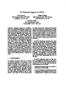
NT sources and Nr receivers are randomly deployed in the network graph. A receiver join randomly a group. Table I summarizes the parameters used in the simulation. The forwarding table size in all routers in the network using the pure random sparse model is shown in Fig.3 and using the waxman model is shown in Fig.4.
3000
2500
PIM-3 MMT-3 PIM-6 MMT-6 PIM-9 MMT-9 PIM-12 MMT-12 PIM-15 MMT-15 PIM-18 MMT-18
0 10
15
20
25
30 35 40 45 Percentage of sources in the network
50
55
60
Fig. 4. Forwarding table size - Waxman model
unicast traffic engineering. We have presented several MPLS proposals for multicast TE. We have described our approach, the MPLS multicast tree protocol which utilizes MPLS LSPs between multicast tree branching node routers in order to reduce forwarding states and enhance scalability. We have discussed the realization of a simulator for MMT and finally we have presented some simulation results.
2000
Forwarding table size
200
R EFERENCES
1500
1000
500
0 10
15
20
25
30
35
40
45
50
55
60
Percentage of sources in the network
Fig. 3. Forwarding table size - pure random sparse mode model
The horizontal axis is the percentage of sources that are active in the network, and the vertical axis is the overall forwarding table size in the network. The poly-lines labeled PIM-x and MMT-x show the overall forwarding table size for PIM-MPLS and MMT protocols respectively when the number of receivers per group is x. The forwarding table size grows with the number of active groups and the number of receivers. From Fig. 4 and Fig. 3 we can see that the relative state reduction of MMT is roughly 40% and 80% respectively compared to PIM-MPLS. We deduce also that our protocol is more suitable for sparse mode networks and for groups with few members. VI. C ONCLUSION AND F UTURE W ORKS In this paper, we have presented a framework for multicast traffic engineering. We have defined multicast traffic engineering and we have studied its particularity comparing to
[1] E. Rosen, A. Viswanathan, and R. Callon. Multiprotocol label switching architecture. IETF RFC3031, January 2001. [2] X. Xiao, A. Hannan, B. Bailey, and L. Ni. Traffic engineering with MPLS in the Internet. IEEE Network, 14(2):28–33, March/April 2000. [3] C. Yang and A. Reddy. A taxonomy for congestion control algorithms in packet switching networks. IEEE Network, 9(5), July/August 1995. [4] D. Ooms, W. Livens, A. Acharya, F. Griffoul, and F. Ansari. Framework for IP multicast in MPLS. IETF Internet draft, January 2002. [5] A. Boudani, C. Jawhar, B. Cousin, and M. Doughan. A simulator for multicast routing over an mpls network. Technical report 1493, IRISA, October 2002. [6] D. Estrin et al. Protocol Independent Multicast-Sparse Mode (PIM-SM): Protocol Specification. IETF RFC 2362, 1998. [7] D. Farinacci, Y. Rekhter, and E. Rosen. Using PIM to distribute MPLS labels for multicast routes. IETF Internet draft, November 2000. [8] G. ahn and W. Chun. Overview of MPLS network simulator: Design and implementation. Chungnam National University, Korea,http://flower.ce.cnu.ac.kr/ fog1/mns. [9] A. Acharya, F. Griffoul, and F. Ansari. Ip multicast support in mpls networks. IETF Internet draft, February 1999. [10] C-Y. LEE, L. Andersson, K. Carlberg, and B. Akyol. Engineering paths for multicast traffic. IETF Internet draft, October 1999. [11] A. Fei, J. Cui, M. Gerla, and M. Faloutsos. Aggregated multicast: An approach to reduce multicast state. In Proceedings of the Third International COST264 Workshop (NGC 2001) UCL. London, number 2233 in LNCS, pages 172–188, november 2001. [12] D. Ooms, R. Hoebeke, and P. Cheval. Mpls multicast traffic engineering. IETF Internet draft, February 2001. [13] J. Chung, M. Benito, H. Chhabra, G. Cho, and P. Rasiah. Ldp extensions for mpls multicasting services. IETF Internet draft, February 2002. [14] J. Chung, M. Benito, H. Chhabra, G. Cho, and P. Rasiah. Rsvp-te extensions for mpls multicasting services. IETF Internet draft, February 2002. [15] A. Boudani and B. Cousin. A new approach to construct multicast trees in mpls networks. In Seventh IEEE Symposium on Computers and Communications, pages 913–919, 2002. [16] B. Cain, S. Deering, B. Fenner, I. Kouvelas, and A. Thyagarajan. Internet group management protocol, version 3. IETF Internet draft, January 2002. [17] K. Fall. and K. Varadhan. The NS Manual. UC Berkeley, LBL, USC/ISI, and Xerox PARC, January 2001. [18] E. Zegura, K. Calvert, and S. Bhattacharjee. How to model an internetwork. In INFOCOM, 1996.
[19] B. Waxman. Routing of multipoint connections. IEEE Journal on Selected Areas in Communications, 6(9):1617–1622, December 1988. Ali Boudani received his B. Eng degree from the Lebanese University, in 1994. He is currently a PhD student in Computer Engineering at the University of Rennes1 and he is working in the Labs of the IRISA/INRIA Rennes. His research interrests include multicast, QoS and traffic engineering.
Bernard Cousin is professor at the University of Rennes 1 (France). He is member of a research group on networking at IRISA (CNRS-INRIA-University joint reseach laboratory in computing science located in Rennes). His main research topics include high speed networking, trafic engineering, multicast routing, QoS management and network security.
Jean-Marie Bonnin received his PhD in 1998 at the university of Strasbourg (France). His PhD work was on large scale reliable multicast mechanisms. He is now associate professor at the ENST bretagne (France). He is member of the INRIA’s ARMOR team, a research group specialized in computer science in Rennes. His main research topics include MPLS and trafic engineering, as well as the QoS management in 3G IP core networks.