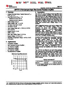
The V.21 modem standard modulation and demodulation algorithms ..... The V.21
FSK modulator/demodulator is implemented with a combination of MSP430.
Application Report SLAA204 – July 2004
MSP430 Embedded Soft-Modem Demo Wolfgang Lutsch
MSP430 ABSTRACT
This application report describes in detail the implementation of a V.21 modem using an MSP430 microcontroller. The V.21 modem standard modulation and demodulation algorithms are implemented in software and are supported by MSP430 hardware peripherals. The presented solution consists of both hardware (schematic, BOM) and software (C source code). Contents 1 Introduction .....................................................................................................................................3 2 V.21 Modem Standard for Use in the PSTN ..................................................................................3 3 Hardware Description .....................................................................................................................5 3.1 Demo Board Circuit Description ................................................................................................5 3.2 LITELINK III Evaluation-Board (DAA) .......................................................................................6 3.3 Interfacing to the DAA ...............................................................................................................6 3.3.1 Control Signals ..............................................................................................................6 3.3.2 Transmit Signal Path .....................................................................................................7 3.3.3 Receive Signal Path ......................................................................................................7 4 Software Description ......................................................................................................................8 4.1 Ring-Detection Module..............................................................................................................8 4.2 V.21 Module ............................................................................................................................10 4.2.1 FSK Modulator.............................................................................................................11 4.2.2 FSK Demodulator ........................................................................................................13 4.2.3 Negotiation Handshake and Switch Hook Control.......................................................16 4.2.4 Soft-Modem Module Operation ...................................................................................16 4.3 Soft-Modem Application Demo................................................................................................18 5 MSP430 Hardware Resources......................................................................................................19 6 Summary........................................................................................................................................20 7 References.....................................................................................................................................21 Appendix A. Application Schematic....................................................................................................22 Appendix B. Bill of Materials ...............................................................................................................23
Figure 1. Figure 2. Figure 3. Figure 4. Figure 5. Figure 6. Figure 7. Figure 8.
Figures Signals for ASCII Character ‘K’.........................................................................................4 V.21 Data Channels Frequency Spectrum .......................................................................4 Soft-Modem Hardware Block Diagram .............................................................................5 Receive Signal ....................................................................................................................8 Ring Signals........................................................................................................................9 Ring Detection Algorithm, P2.5 ISR..................................................................................9 Ring Detection Algorithm, WDT ISR...............................................................................10 FSK Modulator Function Blocks.....................................................................................11
1
SLAA204 Figure 9. Figure 10. Figure 11. Figure 12. Figure 13. Figure 14. Figure 15. Figure 16. Figure 17. Figure 18.
P1.3 ISR Flow Chart .........................................................................................................12 FSK Modulator Waveforms .............................................................................................12 Timer_A.CCR1 Capture ISR.............................................................................................13 Timer_A.CCR0 Compare ISR...........................................................................................14 Timer_A.CCR1 and CCR0 ISR Interaction......................................................................15 FSK Demodulator Function Blocks ................................................................................15 V.21 Negotiation Handshake ...........................................................................................16 Modem State Machine......................................................................................................17 V.21 Module Usage...........................................................................................................18 MSP430 Soft-Modem Test Setup ....................................................................................18
Table 1. Table 2. Table 3. Table 4. Table 5. Table 6.
Tables Frequency Specification for V.21 FSK .............................................................................3 Switch-Hook Control..........................................................................................................6 Transmit Signal Levels ......................................................................................................7 Software Modules Overview..............................................................................................8 Period Values for FSK Demodulation.............................................................................14 User Interface ...................................................................................................................19
2
MSP430 Embedded Soft-Modem Demo
SLAA204
1 Introduction The purpose of this application note is to show how basic modem functionality can be added to a microcontroller application. Only a few hardware components are needed to gain access to the telephone line. This interface is provided by a direct access arrangement (DAA) evaluation board. The current Soft-Modem demo application is designed for inbound connections only. A simple demo application is provided to show the usage of the Soft-Modem implementation. Furthermore, this application report describes how to establish a connection between the MSP430 Soft-Modem and PC standard modem.
2 V.21 Modem Standard for Use in the PSTN The main function of a modem is to modulate and demodulate binary information into analog signals that can be transmitted over the band-width limited analog telephone line. The CCITT/ITU standard papers specify different modem standards with their corresponding modulation implementation. Below is an overview of the V.21 specifications: •
Full-duplex point-to-point connection for data transmission over the telephone line
•
Frequency Shift Keying (FSK) binary modulation
•
300-bps communication speed
The V.21 FSK modulation is specified as followed: •
•
Two frequency channels for each transmission direction –
Channel 1 with a center frequency of f1 = 1080 Hz
–
Channel 2 with a center frequency of f2 = 1750 Hz
Characteristic frequencies for binary ‘1’ (MARK) and binary ‘0’ (SPACE) in each channel –
fMARK = fx – 100 Hz
–
fSPACE = fx + 100 Hz where fx is to be substituted with the center frequency of the corresponding channel (see Table 1 for resulting values)
•
Calling modem transmits data on channel 1 and receives data on channel 2 (originate mode)
•
Called modem transmits data on channel 2 and receives data on channel 1 (answer mode) Table 1.
Frequency Specification for V.21 FSK
Center Frequency
Channel 1
Channel 2
f1 = 1080 Hz
f2 = 1750 Hz ∆f = 100 Hz
Characteristic Frequency Binary ‘1’
980 Hz
1650 Hz
Binary ‘0’
1180 Hz
1850 Hz
MSP430 Embedded Soft-Modem Demo
3
SLAA204 The V.21 standard allows a variation of the frequencies at the modulators output of ±6 Hz. The demodulator should be able to recognize frequencies within a range of ±12 Hz from the expected values. V.21 is specified for data transmission in either synchronous or asynchronous mode. For a standard point-to-point dial-up connection, the asynchronous mode with one start bit, eight data bits, and one stop bit is used. Figure 1 shows a binary and FSK-signal for the ASCII character ‘K’ (0x4B). Data is transmitted with the least significant bit (LSB) first. UBIN Vcc (MARK)
GND (SPACE)
0
1
1
0
1
0
0
1
0
1
t UFSK UFSKmax GND t -UFSKmax
Start Bit
Stop Bit
Data Bits
NOTE: Waveforms are not to scale. Figure 1.
Signals for ASCII Character ‘K’
The MSP430 Soft-Modem implementation is designed for answer mode only. Therefore, the tasks of the two different communication channels can be constituted as shown in Figure 2. The MSP430 Soft-Modem implementation transmits data on channel 2 and receives data on channel 1. Reception (Channel 1)
Transmission (Channel 2)
A(f)
f1-∆f
Figure 2.
4
f1
f1+∆f
f2-∆f
f2
f2+∆f
f
V.21 Data Channels Frequency Spectrum
MSP430 Embedded Soft-Modem Demo
SLAA204
3 Hardware Description 3.1
Demo Board Circuit Description The MSP430 Soft-Modem application consists of two hardware boards. One board contains the MSP430F149 microcontroller. This device could be substituted by lower-end MSP430 family members such as the MSP430F1121. The other board contains the LITELINK III Phone Line Interface IC from Clare/Ixys. The complete DAA circuit is provided by an evaluation board that is used as a daughter board to be connected to the MSP430 Soft-Modem circuitry. The part number of this board is CPC5621-EVAL-RDL (resistive ac-termination circuit, US) or CPC5621EVAL-CDL (reactive ac-termination circuit, EU). In addition to the MCU, the following components are used: •
A 3.3-V voltage regulator to provide a stable power supply
•
A JTAG interface connector for in-system programming and debugging
•
An OP-amp IC for signal conditioning
•
An RJ11 connector to interface with the phone line
•
Three LEDs to signal:
•
–
Correct power supply
–
Connection status of the modem
–
Data traffic on the link
A pin header to access port pins P6.6 and P6.7, as well as Vcc and GND RING OH 32 kHz LITELINK III Eval Board
Signal Conditionning
MSP430F149
+ -
RJ11 Connector
Figure 3.
3.3-V Power Supply
LEDs: Power, Link, Traffic
Soft-Modem Hardware Block Diagram
See Appendix A for the complete Soft-Modem demo board schematic. Appendix B provides a list of components that are needed to build the demo board.
MSP430 Embedded Soft-Modem Demo
5
SLAA204 3.2
LITELINK III Evaluation-Board (DAA) The LITELINK III is a single-chip DAA used in voice and data communication applications to make connections between host equipment and the telephone network. It provides a highvoltage isolation barrier, ac and dc phone line terminations, switch-hook functionality, a ring detection circuit, and on-hook signal detection. It can be used in both differential and singleended signal applications. The MSP430 Soft-Modem application uses the DAA in single-ended mode. A few external components are needed to form a complete phone line interface, as the highvoltage isolation barrier is already integrated into the chip. The evaluation board that is used provides a preconfigured and tested circuit that makes it easy-to-use and complies with given standards right out of the box. As the line side of the phone line interface IC is powered from the phone line, no additional electrical isolated power supply is necessary. The host-side can operate from a 3.3-V power supply that makes it well suited to interface directly to the MSP430. For further information on the LITELINK III chip, see the CPC5620/CPC5621 LITELINK III Phones Line Interface IC (DAA) data sheet and the CPC5621 Evaluation Board user’s guide from Clare Inc. See the Reference section.
3.3
Interfacing to the DAA
3.3.1 Control Signals The MSP430 Soft-Modem application uses two DAA control signals, which are directly connected to MSP430 I/O port pins. The first control signal is the output signal of the LITELINK III ring detection circuit called RING and is directly connected to the MSP430 interrupt-capable port pin P2.5. The RING output signal is usually held high, it outputs high-to-low pulses on zero crossings of the incoming ring signal. The second control signal connection is the switch-hook control input to the DAA called OH. It is connected to P2.1, which is operated as an output pin. Table 2 shows the two different operating modes. Table 2.
6
Switch-Hook Control
OH
Operation Mode
High
On-hook state
The DAA is ready to make or receive a call, the snoop circuit is active and monitors the telephone line, and an incoming call will be signaled on the ring output pin.
Low
Off-hook state
Loop current flows through the circuitry and the system is answering or placing a call.
MSP430 Embedded Soft-Modem Demo
Description
SLAA204 3.3.2 Transmit Signal Path The output of the MSP430 FSK modulator on pin P1.7 (TA2) is a square-wave signal with an amplitude of 3.3V. This output is fed into a voltage divider (R10, R11) that limits the signal amplitude. An additional capacitor (C11) provides a simple first order low-pass filter that rejects high-frequency components in the signal. The following are two reasons for limiting the amplitude of the FSK output signal: •
The LITELINK III IC allows a maximum transmit level of 1.1 V in single-ended mode. This transmit level corresponds with a level of -6 dBm at 600 Ω on the telephone line
•
Transmit signal level of modem applications has to be in the range of -43 dBm to -9 dBm
Table 3 shows the resulting signal levels of the generated 1650-Hz and 1850-Hz FSK output frequencies with the combination of an output divider and a low-pass filter as used in the implementation (see Appendix A).
U tx 2 2⋅ 2 P (U tx ) = 10 ⋅ log 600Ω ⋅1mW
U tx ( f ) =
(3.1)
1 1 + j ⋅ 2π ⋅ 9.1kΩ ⋅ 10nF ⋅ f
Table 3.
(3.2)
Transmit Signal Levels
Frequency (f)
Signal Level P(Utx)
1650 Hz
-24 dBm
1850 Hz
-24.5 dBm
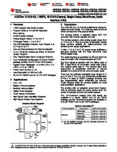
3.3.3 Receive Signal Path The incoming ac signal will first be pre-biased with Vcc/2 (R12, R13, see the schematic) and amplified by IC2A by a factor of 18. Furthermore, the signal passes a second order active lowpass filter that provides bandwidth limitation with a cutoff-frequency of 1.3 kHz, as the incoming signal frequencies are expected to be in the range of 980 Hz to 1180 Hz. The resulting signal is now fed into the MSP430 Comparator_A module via P2.3 for demodulation. Figure 4 shows a before (channel 1) – after (channel 2) comparison of the receive signal. The RX+ signal contains several distortions caused by the transmission channel and also some components of the MSP430 FSK modulator signal as both transmit and receive signal are modulated on the same transmission line.
MSP430 Embedded Soft-Modem Demo
7
SLAA204
Figure 4.
Receive Signal
4 Software Description This chapter describes the implementation of the ring signal detection algorithm and the V.21 module. The V.21 FSK modulator/demodulator is implemented with a combination of MSP430 hardware modules and software (written in C). The ring detection and V.21 modules are interrupt-driven, once initialized they operate in the background. The project is separated into different modules (see Table 4). Table 4.
Software Modules Overview
Module
4.1
Description
Application (softmodem.c, softmodem.h)
Implements a simple application with a user interface using the V.21 module to exchange data over a modem connection.
V.21 Module (v_21.c, v_21.h)
Provides all the routines and ISRs to implement V.21 modem functionality in a user application including functions to handle UART communication.
Ring Detection (ring_detection.c, ring_detection.h)
Contains the ring detection initialization and time base algorithm functions used by the V.21 module.
Ring-Detection Module An incoming call is signaled by an ac-ring tone with a voltage in the range of 48 V to 60 V and a frequency in the range of 16 Hz to 64 Hz. The signal is sent in bursts of 1s length and about 4s of silence in between (see Figure 5). The ring signal parameters are dependent on countryspecific standards.
8
MSP430 Embedded Soft-Modem Demo
SLAA204 UPHONE Umax 0V t -Umax URING Vcc
GND t 1s
4s
Figure 5.
1s
Ring Signals
The RING output is connected to pin P2.5. As the incoming signal can get distorted by noise or other phone line phenomena, just counting pulses would not be a reliable approach to detect an incoming call. A time-controlled software algorithm is used instead to qualify the signal as a valid ringing signal. This algorithm consists of the P2.5 ISR (see Figure 6) and the WDT ISR (see Figure 7). The WDT ISR is executed every 250 ms to implement time-based control. P2.5 ISR
ring_puls_cntr++
Is 1st pulse?
y
Start WDT Timer (250-ms Interval)
n
15 pulses detected?
y
Disable P2.5 Int., set ValidRingFG
n RETI
Figure 6.
Ring Detection Algorithm, P2.5 ISR
MSP430 Embedded Soft-Modem Demo
9
SLAA204 WDTISR (250-ms interval)
t = 250 ms & ring_puls_cntr > 1?
n Re-init ring detection, stop timer
y
t = 750 ms & Valid RingFG set?
RETI
n
Re-init ring detection
y
n
t = 2s? y
Enough ring-bursts detected?
Increment ValidRing_cntr
n Switched to off-hook mode?
y Switch to off-hook mode n
y n t = 4s?
y SetOFF_HOOK flag, stop timer
t = 10s?
n
y Re-init ring detection, stop timer
RETI
Figure 7.
4.2
Ring Detection Algorithm, WDT ISR
V.21 Module Simplifications were applied when implementing the V.21 standard. The FSK modulator outputs a square wave instead of a sine wave which reduces complexity. Furthermore, incoming frequencies are demodulated by measuring the signal period width. The hardware USART module is used to generate the outgoing bit stream, collect incoming bits, as well as to provide an API.
10
MSP430 Embedded Soft-Modem Demo
SLAA204 The MSP430 internal DCO is used to provide the time base for the modulation/demodulation algorithms. The DCO frequency is set and stabilized to a multiple of 4096 Hz by calling the function Set_DCO(). The DCO frequency can be modified by changing the value of the constant DELTA as defined in the file v_21.h. The DCO frequency default value is set to 1.024 MHz (DELTA = 250), so that the generated output frequencies of the FSK modulator are still within the tolerance window of ±6 Hz according to the V.21 specification. The chosen DCO frequency should not be lower than 999 kHz as this causes a specification violation. All the corresponding timing constants described later can be found in the V.21 modules header file and are calculated during compile time depending on the selected DCO frequency. The DCO is used to drive both MCLK and SMCLK.
4.2.1 FSK Modulator The USART0 module is used as an interface between the user’s application and the modulator software itself (see Figure 8). It is configured to UART mode and initialized for asynchronous operation with 300 bit/s. When a data byte is written to the U0TXBUF, the USART module starts outputting a corresponding bit stream on the UTXD0 pin, consisting of a start and stop bit as well as the eight data bits starting with the LSB. MSP430F149 FSK Modulator
UTXD0 Output
USART0 (UART Mode) Transmitter
P1.3 Input
P1.3 ISR, Timer_A.CCR2 Compare ISR
Figure 8.
Timer_A.CCR2 Compare Logic
P1.7 Output
FSK Modulator Function Blocks
This output pin is externally connected to pin P1.3. The Timer_A.CCR2 capture/compare block is operated in compare mode and used for PWM signal generation. With Timer_A running and CCR2 output mode set to toggle, a PWM signal is output on pin P1.7. The values which are periodically added to CCR2 to output a given frequency are calculated using the following formula.
HalfPeriodValue =
Timer _ A. CLK 2 ⋅ SignalFrequency
The digital I/O port pin P1.3 is configured as an input with interrupts enabled. Its ISR is entered on every transition of the UTXD0 signal. Figure 9 shows the corresponding ISR flow chart.
MSP430 Embedded Soft-Modem Demo
11
SLAA204 P1.3 ISR
Falling edge detected?
Now output 1850 Hz y
n Now output 1650 Hz
Toggle P1.3 IES
RETI
Figure 9.
P1.3 ISR Flow Chart
By reading out P1IES.3, the ISR determines if the signal transition that caused the interrupt was high-to-low or low-to-high. According to this, the variable BitFreq which is holding the current period value for PWM generation is updated. This results in a square-wave output signal depending on the UART bit stream (see Figure 10). UUTXD0 P1.3 ISR Trigger Vcc (MARK)
GND (SPACE)
0
1
1
0
1
0
0
1
0
1
t UP1.7 Vcc
GND Start Bit
Data Bits
Figure 10. FSK Modulator Waveforms
12
MSP430 Embedded Soft-Modem Demo
Stop Bit
t
SLAA204 4.2.2 FSK Demodulator After passing the OP-amp circuit, the receive signal is feed into the Comparator_A module via pin P2.3 (CA0), where it is compared with an internal reference of Vcc/2. Using the Timer_A.CCR1 capture/compare block, the period width of the incoming signal is measured. The capture event is triggered by the output of the Comparator_A module on every received signal zero crossing. Figure 11 shows the flow chart of the CCR1 capture ISR. Timer_A.CCR1 ISR
Falling edge captured?
y
Calc tDiff from last falling edge
n Calc tDiff from last rising edge
tDiff = 1/1180 Hz?
Zeros++ y
n
tDiff = 1/980 Hz?
Ones++ y
n RETI
Figure 11. Timer_A.CCR1 Capture ISR The ISR reads out the captured CCR1 value and the period width of the incoming signal is determined by calculating the time difference between a pair of transitions. This value is compared with the period values for the ‘MARK’ (980 Hz) and ‘SPACE’ (1180 Hz) frequencies using a tolerance window (CHN1_MARGIN). The period values are calculated by the following formula. Table 5 shows the values used in the actual implementation.
PeriodValue =
Timer _ A CLK SignalFrequency
MSP430 Embedded Soft-Modem Demo
13
SLAA204 Table 5.
Period Values for FSK Demodulation
Parameters used: Timer_A CLK = 1.024 MHz, CHN1_MARGIN = 88 Characteristic Frequency
Period Value
Tolerance Window Period Values
Frequencies
1180 Hz
867
955 – 779
1072 Hz – 1315 Hz
980 Hz
1044
1132 – 956
905 Hz – 1071 Hz
If the comparison of the signal periods matches, one out of two period-counters (ones or zeros) is incremented. As soon as a start bit was detected (recognition of six ‘SPACE’ periods), the Timer_A.CCR0 capture/compare block is used in compare mode to trigger interrupts every 1/300s which is the bit rate of the communication channel. Every time the ISR is executed, a majority vote is used to determine whether the last received bit was a one or a zero by comparing the period-counters which are incremented by the Timer_A.CCR1 ISR. According to the result of this comparison, the digital I/O pin P1.2 is set and the period-counters are cleared to prepare the demodulation of the next bit (see Figure 12). Timer_A.CCR0 ISR
++BitCounter > 9?
Disable CCR0 Int. y
n
Ones > Zeros?
Set P1.2 y
n Clear P1.2
Zeros=0, Ones=0
RETI
Figure 12. Timer_A.CCR0 Compare ISR A variable is used to keep track of how many bits of a received byte have been collected already (BitCounter). After eight data bits have been decoded, Timer_A.CCR0 interrupts are disabled and a stop bit is generated. The resulting bit stream is output with 300 bps on pin P1.2. Figure 13 shows a summary of the interaction of the ISRs.
14
MSP430 Embedded Soft-Modem Demo
SLAA204 UCA0 CCR1 Capture ISR Trigger Vcc Vref GND t UURXD0 CCR0 Compare ISR Vcc (MARK)
GND (SPACE)
0
1
1
0
Start Bit
1
0
0
1
0
1
Stop Bit
Data Bits
t
Figure 13. Timer_A.CCR1 and CCR0 ISR Interaction P1.2 is externally feed back into the USART0 module URXD0 pin. The USART module is then used in UART mode to collect the bit stream and to provide an interface to the application (see Figure 14). The corresponding receive interrupt can be used to handle received bytes. MSP430F149 FSK Demodulator
P2.3 Input
Comparator_A,T imer_A.CCR1 Capture ISR
USART0 (UART Mode) Receiver
URXD0 Input
Timer_A.CCR0 Compare ISR
P1.2 Output
Figure 14. FSK Demodulator Function Blocks
MSP430 Embedded Soft-Modem Demo
15
SLAA204 4.2.3 Negotiation Handshake and Switch Hook Control Before exchanging data over the telephone line the involved modems have to negotiate a common communication standard. As this process is time controlled, the Timer_A.CCR0 capture/compare block is operated in compare mode to provide the time base. The Timer_A.CCR0 ISR is called every 1/300s and handles the complete handshake algorithm (see Figure 15).
Caller
Calling...
Called
Call Taken
Ring Detection
Detect V.21
Answer Tone 2100 Hz
2150 ms
3300 ms
Binary Ones 980 Hz
Binary Ones 1650 Hz
75 ms
x ms
155 ms
Data
Data
t
600 ms
Figure 15. V.21 Negotiation Handshake After the ring tone detection algorithm has qualified an incoming call as valid, the MSP430 SoftModem changes into the off-hook state. At this point the DAA reception and transmission signal paths are fully active and the MSP430 gains access to the communication channel. After an initial silence period of 2150 ms (2 seconds of that period come from the ring tone detection algorithm), the MSP430 Soft-Modem sends out an answer tone which is a frequency of 2100 Hz and a duration of 3300 ms. This is done by operating the Timer_A.CCR2 capture/compare block in compare mode and initializing it for 2100-Hz output. After an additional silence period of 75 ms, the MSP430 Soft-Modem FSK modulator is started and binary ones (1650 Hz) are transmitted to the caller. The calling modem unit has time now to recognize the transmission according to V.21. As soon as the V.21 standard has been detected, the caller itself starts sending out binary ones (980 Hz). It is necessary that at least 155 ms of this signal are recognized by the MSP430 Soft-Modem. This is done by counting signal periods within the Timer_A.CCR1 capture ISR. As soon as sufficient signal periods have been counted (DetectTime_Chn1) the two modems wait for another 600 ms, while continuing sending binary ones, until the data transmission starts.
4.2.4 Soft-Modem Module Operation To use the V.21 modem implementation only two functions need to be called by the user application. A state machine which is implemented in the modem() function is used to keep track of the current operating mode as a connection gets established or terminated. The second function is ModemInit(). When calling this function, the internal module state changes to CommandMode. This is the initial state in which the module is setup to wait for an incoming call. ModemInit() also performs a basic initialization of the V.21 Soft-Modem. Figure 16 shows the simplified state machine. It does not include certain transitions such as time-out events which would change the state back to CommandMode.
16
MSP430 Embedded Soft-Modem Demo
SLAA204
RING-Edge
Ring Detection
Command Mode
OFF_HOOK = 1
Answering Handshake
OnesDetected
OFF_HOOK = 0 Data Mode
Figure 16. Modem State Machine The first transition of the ring signal activates the RingDetection state. As soon as a valid incoming call is detected, the ring detection algorithm will accept the call and set the OFF_HOOK status flag. This switches to the AnsweringHandshake state. After the negotiation handshake, the state machine switches to DataMode. Now the modem is fully active and data transfer over the phone line is possible by simply accessing the MSP430 USART module. The termination of a call by the other peer is recognized by the following algorithm: The periodically called function modem() always resets the OFF_HOOK flag. As long as an incoming signal is available the OFF_HOOK flag will be set again with every detected signal zero crossing (Timer_A.CCR1 ISR). When no incoming signal is available anymore the modem() function generates a time-out event and stops the FSK functions, reinitialize the Soft-Modem application, and switch back into CommandMode. Figure 17 shows the required program flow of a user application that wants to implement the V.21 modem functionality.
MSP430 Embedded Soft-Modem Demo
17
SLAA204 HardwareInit()
ModemInit()
modem()
Handle USART Events
User Application
Figure 17. V.21 Module Usage
4.3
Soft-Modem Application Demo The software example provided with this application report demonstrates the usage of the V.21 module in combination with a simple user interface, which allows reading measurement data from the MSP430. Figure 18 shows a possible test setup. A personal computer with a standard modem is connected to one connector of a phone line simulator and the MSP430 Soft-Modem demo board is connected to another one.
MSP430 Soft Modem Application
Phone Line Simulator
PC w/ Standard Modem (V.21)
Figure 18. MSP430 Soft-Modem Test Setup On the PC side, the Windows Hyper Terminal software can be used. You should make sure that the right COM port is selected and that the port properties are set to 8 data bits, no parity, one stop bit, and hardware flow-control. The selected bit rate is arbitrary, as it is used for communication between the PC and modem only. The modems will negotiate the channel bit rate amongst them.
18
MSP430 Embedded Soft-Modem Demo
SLAA204 After configuring Hyper Terminal the standard modem can be controlled by entering ‘AT’ commands: •
ATZ (performs a modem reset)
•
ATDTx (dials the number sequence x, which should be the number of the telephone extension the MSP430 Soft-Modem is connected to)
After dialing and connection establishment the PC modem responds with a connect message and the MSP430 Soft-Modem application outputs the string MSP430 Soft-Modem Demo on the Hyper Terminal display. By sending characters to the MSP430 Soft-Modem, the demo application software responds with several answer strings that contain various status information (see Table 6). Table 6.
User Interface
Character
Soft-Modem Response
0
MSP430 application software toggles the output level on port pin P1.0 to which the yellow LED is connected. According to the current output level the string “LED on” or “LED off” is sent back.
6
The current state of P6.6 input pin is reported. Depending on the current state the string “P6.6 Input: HIGH” or “P6.6 Input: LOW” is sent back.
7
Same as above, but for input pin P6.7.
t
The result of the AD-conversion of the internal temperature sensor is sent back.
x
The MSP430 Soft-Modem sends the string “Good Bye!” and terminates the modem connection.
Any other
The received character is echoed.
5 MSP430 Hardware Resources The V.21 Soft-Modem implementation uses the following resources: •
Timer_A3
•
Comparator_A
•
USART module
•
Watchdog timer
•
Two digital I/O pins
•
1.7KB of Flash memory, 100 Byte of RAM
MSP430 Embedded Soft-Modem Demo
19
SLAA204
6 Summary All of the tested standard modems were able to connect to the MSP430 Soft-Modem without any problems. It has been shown that modem functionality can be realized on a very basic level with a microcontroller to enable applications exchanging data over the telephone network without using an external modem device. This can be a cost-effective approach for applications to report small amounts of data to a host system.
20
MSP430 Embedded Soft-Modem Demo
SLAA204
7 References 1. 2. 3. 4.
MSP430x13x, MSP430x14x Mixed Signal Microcontroller data sheet (SLAS272) MSP430x1xx Family user’s guide (SLAU049) CPC5620/CPC5621 LITELINK III Phone Line Interface IC (DAA) data sheet, Clare Inc., 2002 CPC5621-EVAL-RDL/CPC5621-EVAL-CDL LITELINK III Evaluation-Board user’s guide, Clare Inc., 2002 5. MSP430 Embedded Soft-Modem Demo, ATC Presentation by Dannenberg, A., November 2003
MSP430 Embedded Soft-Modem Demo
21
SLAA204
Appendix A. Application Schematic
22
MSP430 Embedded Soft-Modem Demo
SLAA204
Appendix B. Bill of Materials Part Name
Value/Description
Package
R1, R9
100 kΩ
1206
R2
10 kΩ
1206
R3
180 kΩ
1206
R4
2 kΩ
1206
R5
22 kΩ
1206
R6, R7, R8, R11
560 Ω
1206
R10
9.1 kΩ
1206
R12, R13
51 kΩ
1206
C1, C2, C3, C4, C5, C8,C10
0.1 µF
1206
C6
2.2 µF/50
Ø 4 mm
C7
47 µF/16
Ø 6,3 mm
C9
4700 pF
1206
C11
0.01 µF
1206
C13
47 pF
1206
D1
LED Blue
1206
D2
LED Yellow
1206
D3
LED Red
1206
D4
BAT 48 SMD
1206
Q2
32,768 kHz
IC1
MSP430F149
IC2
TLV2782ID, Texas Instruments operation amplifier
SO-8
IC3
TPS7233QD, Texas Instruments voltage regulator
SO-8
P1
HEBW21/Power Supply Connector
X1
Female Pin Header, 1x2
X2
Female Pin Header, 1x12
X3
Male Pin Header, 2x7
X4
RJ11 Connector
JP1
Male Pin Header, 2x3
TQFP-64
MSP430 Embedded Soft-Modem Demo
23
IMPORTANT NOTICE Texas Instruments Incorporated and its subsidiaries (TI) reserve the right to make corrections, modifications, enhancements, improvements, and other changes to its products and services at any time and to discontinue any product or service without notice. Customers should obtain the latest relevant information before placing orders and should verify that such information is current and complete. All products are sold subject to TI’s terms and conditions of sale supplied at the time of order acknowledgment. TI warrants performance of its hardware products to the specifications applicable at the time of sale in accordance with TI’s standard warranty. Testing and other quality control techniques are used to the extent TI deems necessary to support this warranty. Except where mandated by government requirements, testing of all parameters of each product is not necessarily performed. TI assumes no liability for applications assistance or customer product design. Customers are responsible for their products and applications using TI components. To minimize the risks associated with customer products and applications, customers should provide adequate design and operating safeguards. TI does not warrant or represent that any license, either express or implied, is granted under any TI patent right, copyright, mask work right, or other TI intellectual property right relating to any combination, machine, or process in which TI products or services are used. Information published by TI regarding third-party products or services does not constitute a license from TI to use such products or services or a warranty or endorsement thereof. Use of such information may require a license from a third party under the patents or other intellectual property of the third party, or a license from TI under the patents or other intellectual property of TI. Reproduction of information in TI data books or data sheets is permissible only if reproduction is without alteration and is accompanied by all associated warranties, conditions, limitations, and notices. Reproduction of this information with alteration is an unfair and deceptive business practice. TI is not responsible or liable for such altered documentation. Resale of TI products or services with statements different from or beyond the parameters stated by TI for that product or service voids all express and any implied warranties for the associated TI product or service and is an unfair and deceptive business practice. TI is not responsible or liable for any such statements. Following are URLs where you can obtain information on other Texas Instruments products and application solutions: Products
Applications
Amplifiers
amplifier.ti.com
Audio
www.ti.com/audio
Data Converters
dataconverter.ti.com
Automotive
www.ti.com/automotive
DSP
dsp.ti.com
Broadband
www.ti.com/broadband
Interface
interface.ti.com
Digital Control
www.ti.com/digitalcontrol
Logic
logic.ti.com
Military
www.ti.com/military
Power Mgmt
power.ti.com
Optical Networking
www.ti.com/opticalnetwork
Microcontrollers
microcontroller.ti.com
Security
www.ti.com/security
Telephony
www.ti.com/telephony
Video & Imaging
www.ti.com/video
Wireless
www.ti.com/wireless
Mailing Address:
Texas Instruments Post Office Box 655303 Dallas, Texas 75265 Copyright 2004, Texas Instruments Incorporated